EVAL-ADA4356EBZ
Overview
Software enablement for EVAL-ADA4356EBZ consists of:
GUI option: Analysis, Control, Evaluation (ACE) software, IIO Oscilloscope
Note
Although the GitHub URLs and filenames refer to ADA4355, the software is for ADA4356 as well.
Digital Interface
The EVAL-ADA4356EBZ’s HDL firmware has been developed around the ZedBoard. The embedded Linux stack is based on the IIO (Industrial I/O) architecture, enabling the host PC to communicate with the EVAL-ADA4356EBZ through the ZedBoard with tools such as ACE, Python (through the pyadi-iio package), or MATLAB (with the precision toolbox). Generic, non-specific IIO tools such as IIO Oscilloscope, Scopy, and IIO command line tools can also be used to evaluate the EVAL-ADA4356EBZ’s basic functionality.
The EVAL-ADA4356EBZ interfaces with the ZedBoard through its FMC connector (P3) to configure the ADA4356’s ADC through the 4-wire SPI in LVDS mode. The table below shows the LVDS connections.
PyADI-IIO API
The pyadi-iio python package is composed of drivers that allow users to control and evaluate software-enabled ADI parts through python scripts. A driver for ADA4356 has been created.
The key drivers used in controlling the EVAL-ADA4356EBZ are:
ADA4356: Interacts with the board’s main IC, the ADA4356 uModule. Reads the device’s output.
AD7291: Controls the AD7291 ADC, used in the board’s self-debug circuit.
one-bit-adc-dac: Reads and writes the gain and frequency settings for the ADA4356.
Refer to the Driver Guide section below for key installations and proper driver usage.
Analysis, Control, Evaluation (ACE) Software
The EVAL-ADA4356EBZ hardware can be controlled and configured through the ACE Software. ADI’s “Analysis, Control, Evaluation” (ACE) is a desktop software application that allows the evaluation and control of multiple evaluation systems from across the Analog Devices product portfolio.
The controller board supported by ACE for the evaluation of EVAL-ADA4356EBZ is the ZedBoard.
Note
For ACE installation and documentation instructions, refer to the ACE user guide. Once ACE is installed, open the ACE application and search for the EVAL-ADA4356EBZ board plugin in ACE’s plugin manager, then install or update.
Controlling the EVAL-ADA4356EBZ
Using ACE
The plugin for the EVAL-ADA4356EBZ is available in ACE. The ACE plugin allows the EVAL-ADA4356EBZ’s gain and frequency settings to be configured, board supplies to be measured, and the resulting output waveform to be observed.
To control the EVAL-ADA4356EBZ through ACE, the host PC must first be physically connected to the FPGA using an ethernet cable. The following steps must then be followed:
Open ACE. Within the software, navigate to plugin manager. The plugin manager is where all the available plugins for ADI boards can be found and installed.
In the plugin manager, select the Available Packages dropdown. This checks for plugins that are available for installation; plugins already installed will not be found under this selection and will be under Installed Plugins instead.
Tick the checkbox for Boards, search for ADA4356, then install.
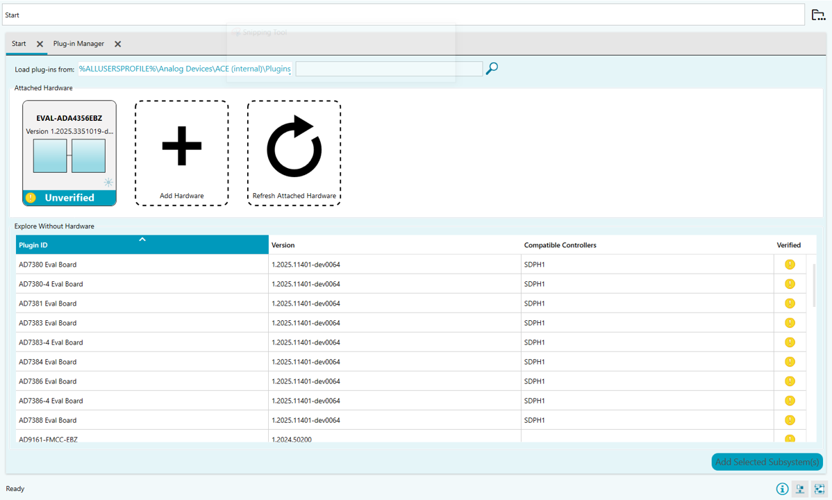
Once installation is complete, restart ACE. Upon rebooting ACE, the evaluation board hardware should be detected, as seen in the screenshot below.
Using IIO Oscilloscope
ADI’s IIO Oscilloscope can be downloaded from the IIO Oscilloscope releases page. Install this on the host PC.
Start IIO Oscilloscope.
Note
It may take a little time for the window to appear after it is launched; do not click multiple times.
Most of the time, IIO Oscilloscope will scan for and discover ADA4355/4356 on its own when it is first opened and show it as ready to connect. If ada4355 shows up under IIO Devices, the system is ready to connect. Click the Connect button in the lower right hand corner to proceed.
If IIO Oscilloscope has not found the ADA4355/4356 yet, select Manual and type in
ip:analog.localand click Connect. The password isanalog(all lowercase).
When the Capture window opens, check the voltage0 checkbox under ada4355 to select the plot channel.
Change the default number of samples to something higher than 400, for example 8192 (= 213).
Click the Enable All button. Once the voltage0 channel has been selected, the orange caution symbols will turn to arrow symbols. To begin reading data, click the gray arrow to Run. This should display the data being gathered by ADA4356 in the plot screen.
To stop data collection, click the red circle where the Run arrow used to be.
Using Python (via pyadi-iio package)
Installing the Assets for Python Programming
In preparation for using the PyADI-IIO package, the following resources must be downloaded and installed.
Python 3.x, libiio, pyadi-iio
Follow these steps to install Python:
Download a preferred version of Python (should be version 3.8 or higher).
Right click on the downloaded .exe file and select Run as Admin. This should open the Python dialog box.
If this is the only Python version to be installed on the device, tick the Add Python 3.x to PATH checkbox.
Select Customize installation.
In Optional Features, proceed with all features checked and click Next.
In Advanced Options, make sure the Install for all Users checkbox is ticked.
Click Install and wait for completion.
Running pip as Admin:
On your Windows start menu, search for cmd. This will show Command Prompt; right click on it and select Run as Admin.
In the command prompt, update the pip package:
py -m pip install --upgrade pip
If multiple Python versions are installed, specifically target your preferred version by adding
-3.x(replace x with actual version number) afterpy.Wait for successful installation. You now have an updated global instance of pip.
Driver Guide
Note
For this guide, variables with my_ prefix refer to
user-defined values.
ADA4356 Driver
The ADA4356 PyADI driver can be used through the following commands:
adi.ada4355(uri=my_uri)— Establishes connection to the on-board ADA4356. Requires a unique resource identifier (URI) attribute. Using the EVAL-ADA4356EBZ mounted on a ZedBoard, this URI should beip:analog.local. This command can be assigned to a variable for easier initialization of other attributes.adi.ada4355(uri=my_uri).rx_buffer_size = my_buffer_size— Initializes the number of data points to be captured and stored.adi.ada4355(uri=my_uri).rx_enabled_channels = [0]— Initializes which channels are enabled. Since ADA4356 only has a single channel, this is set to 0.adi.ada4355(uri=my_uri).ada4355_register_write(0x0D, 0x00)— Directly accesses a register of ADA4356.0x0Daccesses the Test Mode, and0x00sets the Test Mode to OFF; this ensures that the ADA4356 is not initialized in test mode (which outputs example test data rather than actual data).adi.ada4355(uri=my_uri).rx()— Captures the data received by the ADA4356’s internal ADC. The data is in its “codes” form. To convert to voltage, multiply by0.00012207, or useadi.ada4355(uri=my_uri).rx_scale.adi.ada4355(uri=my_uri).rx_destroy_buffer()— Destroys the buffer, thereby also erasing its contents. It is preferred to destroy the buffer and create a new one to capture another set of data to free up memory.
Example code:
import adi

my_uri = "ip:analog.local"
my_buffer_size = 4096

# Assign to variable for easier initialization
my_4356 = adi.ada4355(uri=my_uri)
my_4356.rx_buffer_size = my_buffer_size
my_4356.rx_enabled_channels = [0]
my_4356.ada4355_register_write(0x0D, 0x00)

data = my_4356.rx() * my_4356.rx_scale
# or: my_4356.rx() * 0.00012207

my_4356.rx_destroy_buffer()
AD7291 Driver
adi.ad7291(uri=my_uri)— Establishes connection to the on-board AD7291. Requires a URI attribute. Using the EVAL-ADA4356EBZ mounted on a ZedBoard, this URI should beip:analog.local.adi.ad7291(uri=my_uri).temp0()— Returns the temperature reading of the AD7291 in Celsius. To access raw readings, use.temp0.raw. To access scale value, use.temp0.scale.adi.ad7291(uri=my_uri).voltageX()— Returns the voltage output of each channel in millivolts. ReplaceXwith the channel number minus 1 (Channel 1 is voltage0, Channel 2 is voltage1, etc.). To access raw readings, use.voltageX.raw. To access scale value, use.voltageX.scale.
The corresponding channel assignments are:
Parameter |
Channel Assigned |
|---|---|
3.3V LDO |
voltage0 |
2.5V LDO |
voltage1 |
1.8V LDO |
voltage2 |
1.65V Sense |
voltage3 |
Example code:
import adi

my_7291 = adi.ad7291(uri=my_uri)
print(my_7291.temp0())
print(my_7291.voltage0())
print(my_7291.voltage1())
print(my_7291.voltage2())
print(my_7291.voltage3())
print(my_7291.voltage4())
one-bit-adc-dac Driver
The one-bit-adc-dac can both read and write the logic for setting the gain and frequency. This driver can be used through the following commands:
adi.one_bit_adc_dac(uri=my_uri)— Establishes connection to ADA4356’s digital gain and frequency control. Requires a URI attribute set toip:analog.local.adi.one_bit_adc_dac(uri=my_uri).<channel name>— Reads the value set on the selected channel’s parameter; its value is either 0 (LOW) or 1 (HIGH).
The one-bit-adc-dac has a total of 8 logic channels, but only 4 channels are used to set the ADA4356:
Parameter Name |
Channel Assigned |
Channel Name |
Used in ADA4356? |
|---|---|---|---|
GSEL0 |
voltage0 |
gpio_gsel0 |
Yes |
GSEL1 |
voltage1 |
gpio_gsel1 |
Yes |
GSEL2 |
voltage2 |
gpio_gsel2 |
Yes |
FSEL0 |
voltage3 |
gpio_fsel0 |
Yes |
GSEL3 |
voltage4 |
gpio_gsel3 |
No |
FSEL1 |
voltage5 |
gpio_fsel1 |
No |
To set or change the value of each parameter, run
adi.one_bit_adc_dac(uri=my_uri).<channel name> = my_set,
where my_set is equal to either 0 (LOW) or 1 (HIGH).
Gain and Frequency Settings Truth Table
Setting |
GSEL0 |
GSEL1 |
GSEL2 |
FSEL0 |
|---|---|---|---|---|
133 kOhm |
0 |
0 |
X |
X |
11 kOhm |
0 |
1 |
X |
X |
4.54 kOhm |
1 |
0 |
X |
X |
Current Divider Disabled |
X |
X |
0 |
X |
Current Divider Enabled |
X |
X |
1 |
X |
LPF Bandwidth = 100 MHz |
X |
X |
X |
0 |
LPF Bandwidth = 1 MHz |
X |
X |
X |
1 |
Note: “X” means “Don’t Care”
Current-to-Bits Operation
The EVAL-ADA4356EBZ provides two methods for generating an input current for the ADA4356:
On-board Buffered Howland Current Source (BHCS) driven by an external voltage source.
Avalanche Photodiode (APD) connection via a 3-pin socket.
Both inputs route through a programmable current divider, which can be enabled to extend the measurable range by attenuating higher input currents.
Input selection is controlled by populating a single 0 Ohm (0603) resistor as summarized below:
Populated Resistor |
Selected Input |
Input Type |
Path |
|---|---|---|---|
R7 |
APD |
Current |
APD1 -> ADA4356 |
R17 |
APD |
Current |
APD1 -> Current Divider -> ADA4356 |
R8 |
Buffered Howland Current Source (BHCS) |
Voltage |
J1 -> BHCS -> Current Divider -> ADA4356 |
By default, R8 is populated, enabling the BHCS signal path. In this configuration, the signal chain operates as follows:
VIN (J1) -> Buffered Howland Current Source (BHCS) -> Optional Current Divider -> ADA4356 Input
An external voltage applied at J1 is converted to proportional current by the BHCS, optionally attenuated by the current divider, converted to voltage by the ADA4356’s programmable gain transimpedance amplifier (PGTIA), and finally digitized by the ADA4356’s ADC.
Voltage-to-Current Conversion via BHCS
The Buffered Howland Current Source converts the applied input voltage into a current according to:
IBHCS = VIN / (5 x RS)
Where:
VIN is the voltage applied at connector J1.
RS is the selected BHCS range resistor (R14, R18, or R19). The factor of 5 arises from the internal resistor ratios of the BHCS topology.
The resulting current is sourced or sunk into the subsequent signal chain.
Input Current Range Extension via Current Divider
The input current divider can be enabled to extend the input current range by attenuating the signal current before it reaches the ADA4356’s input. This feature is optional and is controlled by the GSEL2 pin (divider enabled when GSEL2 = 1; disabled when GSEL2 = 0).
The divider is implemented using the ADG772 (U4) analog switch in series with R22 = 604 Ohm. When the divider is enabled, the effective division ratio is primarily determined by the ON resistance of the ADG772 (RON) and R22.
The ADG772 RON is typically 3.8 Ohm, and may vary due to:
Part-to-part variation
Temperature
Supply voltage
Bias conditions
This variability introduces an added gain error term when the divider is enabled.
When the divider is enabled (GSEL2 = 1), the input current is divided as:
ISIG_IN = IBHCS_OUT x RON / (RON + R22)
Using typical values RON = 3.8 Ohm and R22 = 604 Ohm:
ISIG_IN = IBHCS_OUT x 3.8 / (3.8 + 604) = IBHCS_OUT / 160
Where:
IBHCS_OUT is the BHCS output current.
ISIG_IN is the input current presented to the ADA4356.
When the divider is disabled (GSEL2 = 0):
ISIG_IN = IBHCS_OUT
ADA4356 Internal Signal Chain
The ADA4356 includes the following internal functional blocks:
Programmable gain transimpedance amplifier (PGTIA)
Fully differential amplifier (FDA)
Low-pass filter
14-bit, 125 MSPS ADC
Programmable Gain Transimpedance Amplifier (PGTIA)
The PGTIA converts the input current into a voltage and is internally referenced to VTIA_REF = 1.65 V.
The PGTIA output voltage is:
VTIA_OUT = VTIA_REF - ISIG_IN x R
Where:
VTIA_REF is the internal 1.65 V TIA reference.
R is the selected transimpedance gain.
VTIA_OUT is the output voltage of the TIA.
For example, if 11 kOhm transimpedance gain is selected and ISIG_IN = 80 uA, the output of TIA will be:
VTIA_OUT = 1.65 V - 80 uA x 11 kOhm = 0.77 V
Fully Differential Amplifier (FDA)
The PGTIA output feeds into a Fully Differential Amplifier (FDA), whose inverting input is biased to:
VFDA_REF = 0.825 V
The FDA output is given by:
VFDA_OUT = VTIA_OUT - VFDA_REF
Substituting the TIA relationship:
VFDA_OUT = (VTIA_REF - ISIG_IN x R) - 0.825 V
With VTIA_REF = 1.65 V, this simplifies to:
VFDA_OUT = 0.825 V - (ISIG_IN x R)
This indicates that the FDA output voltage decreases linearly with increasing input current.
14-bit, 125 MSPS ADC Transfer Function
The FDA output drives a 14-bit ADC with an input range of approximately +/- 1 V (2 V peak-to-peak). The ADC output code can be modeled as:
ADC code = 214 x VFDA_OUT / VADC_REF
With VADC_REF = 2 VPP, this reduces to:
ADC code = 213 x VFDA_OUT
Substituting the FDA expression derived above:
ADC code = 213 x [0.825 V - (ISIG_IN x R)]
Note that for ISIG_IN = 0, the ADC code will be:
ADC code = 213 x 0.825 V = 6758
This decreases as current into the ADA4356 increases.
Known Hardware Errata
Rev. A, 10/2025 Release
The onboard current sense based on LT6105 is not wired correctly and cannot measure the supply current of the overall 3.3 V supply as originally intended. Please disregard the output of this current sense circuit and its readings in the self-debug ADC output.
Downloads
Download
Boot Files:
4356 Boot Files (Aug 13, 2025) — Based on July 14 version, but fixes Trig In - Trig Out loopback.
4356 Boot Files (July 14, 2025) — First version to support EVAL-ADA4356 with corrected FMC connection for frame clock. Includes support for onboard self-debug ADC. Has bug in Trig In - Trig Out loopback.
ADA4355 Boot Files for ADA4356 on EVAL-ADA4355 Board (March 12)
Warning
These boot file versions are preliminary, use them at your own risk. The official boot files will be released in Kuiper Linux.