ADALM-MMSC
Mixed-Mode Signal Chain Active Learning Module
Overview
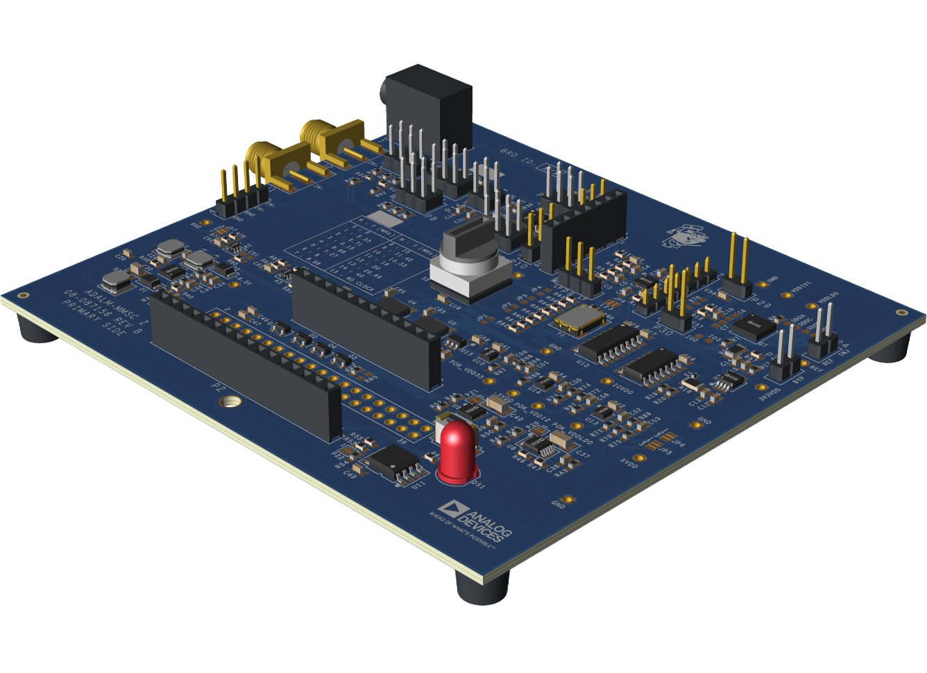
The Analog Devices Active Learning Module-Mixed-Mode Signal Chain (ADALM-MMSC) is an educational board designed to facilitate hands-on exploration of fundamental signal chain concepts.
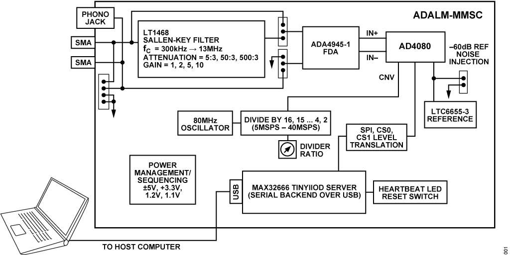
The core of the circuit is the AD4080, a 40 MSPS oversampling SAR analog-to-digital converter (ADC) with a configurable digital filter and internal data capture memory (single-port FIFO).
The board includes a highly configurable 2nd order analog filter with adjustable cutoff frequencies, input attenuation, and filter gain.
An onboard selectable clock source provides sample rates from 5 MSPS to 40 MSPS. A MAX32666FTHR microcontroller runs an IIO server over a serial backend, allowing the use of standard tools such as Scopy, IIO Oscilloscope, Pyadi-iio, and ADI’s MATLAB precision toolbox.
The Libiio library provides language bindings for C, C#, MATLAB®, Python, and other languages.
Concepts demonstrated include:
Digital filtering
Analog vs. digital anti-alias filtering
Properties of different digital filters
Noise analysis
Reference noise
Features
- Multiple input connections
100-mil posts compatible with the ADALM2000
SMA connections for benchtop signal generators
1/8-inch stereo audio jack for connection to sound cards and other audio sources
- Selectable input attenuator
3:5 attenuation allows ±5V input swing
3:50, 3:500 attenuation settings allow testing with low-amplitude signals for dynamic range measurements
- Configurable Sallen-Key filter with low-noise amplifier
Cutoff frequencies between 200 kHz and 8 MHz
Gains of unity, 2, and 5 for exploring noise optimization
- Onboard fully-differential amplifier
Accepts arbitrary input signals
Input and output test connections for monitoring all critical points
- Onboard low-noise reference
Flagship LTC6655 for optimal performance
“Reference Corruption” input allows noise and interfering tones to be introduced and their effects observed
Selectable conversion rates from 5 MSPS to 40 MSPS allow observation of aliasing and ADC noise density vs. sample rate
Applications
Mixed signal and digital signal processing experiments, workshops, and lab exercises
Precision data acquisition
System Architecture
Package Contents
Errata
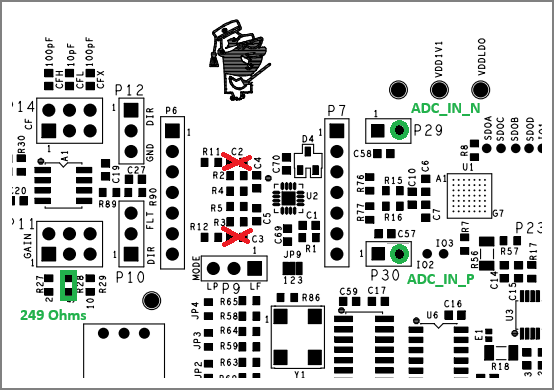
The first production build has three errors:
P7 pins are too short for ADALM2000 fly wires
Resolution: Use P29, P30 for experiments that probe the AD4080 inputs
C2 and C3 should not be installed. Most experiments will work but there is overshoot in the step response and a peak around 2 MHz in the frequency response.
Resolution: Remove C2 and C3. They are easily accessible using two soldering irons or tweezer-style rework iron.
R28 should be 249 ohms, not 249k. Only affects gain = 5 selection.
Resolution: Install 249 ohm, 1% tolerance, 0603 on top of 249 k. The 249k resistor will have negligible ~0.1% impact on gain.
The ADALM-MMSC kit includes the following boards and accessories:
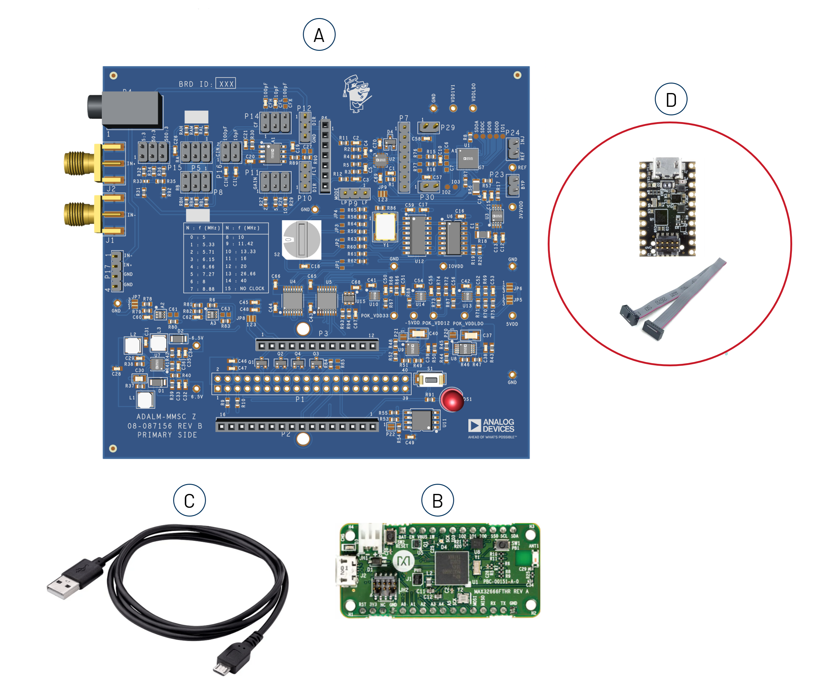
(A.) 1x ADALM-MMSC Board
(B.) 1x Pre-programmed MAX32666FTHR board
(C.) 1x USB-A to Micro-USB cable
(D.) 1x MAX32625PICO with 10-pin ribbon cable for SWD connection (for future firmware upgrades)
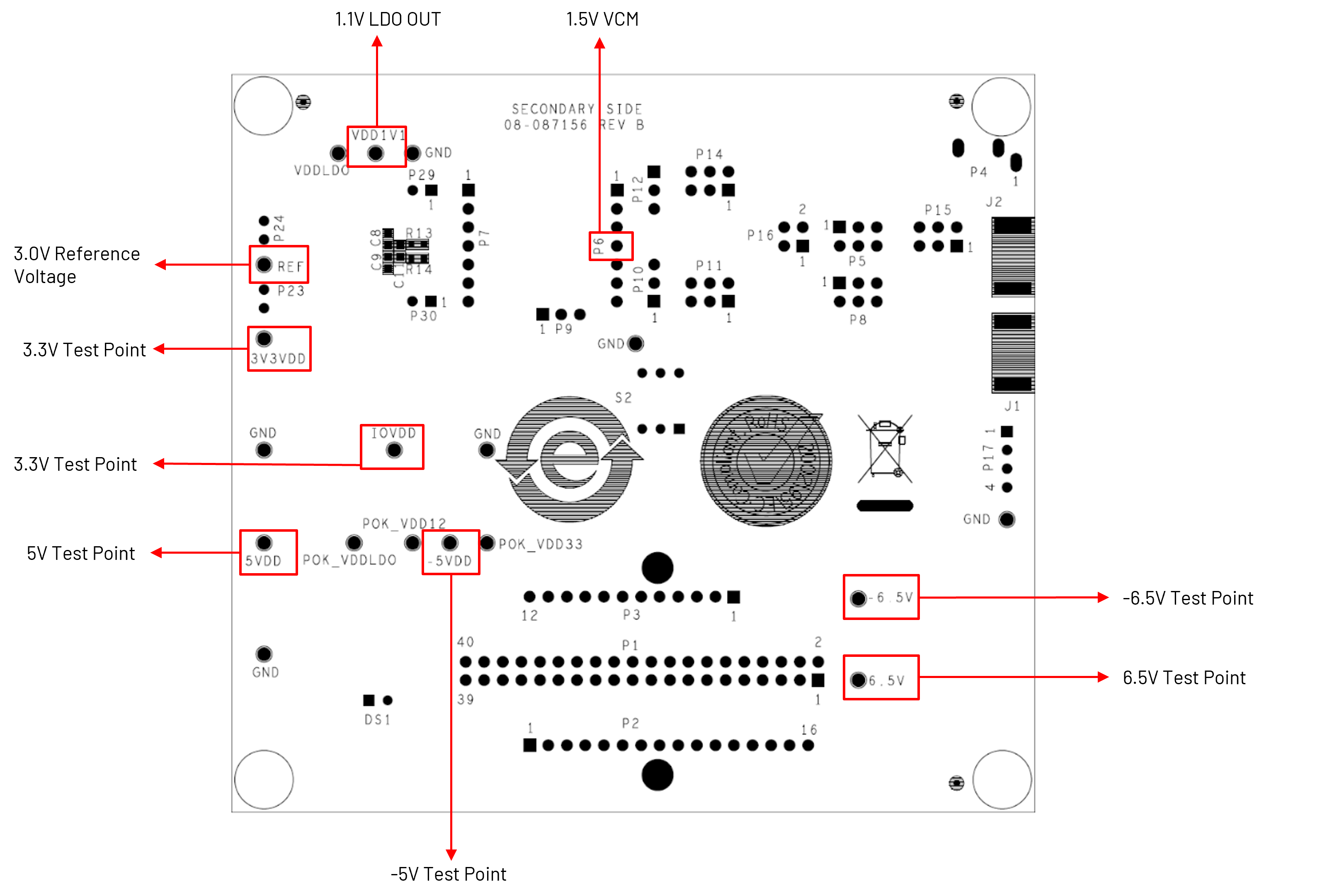
Components and Connections
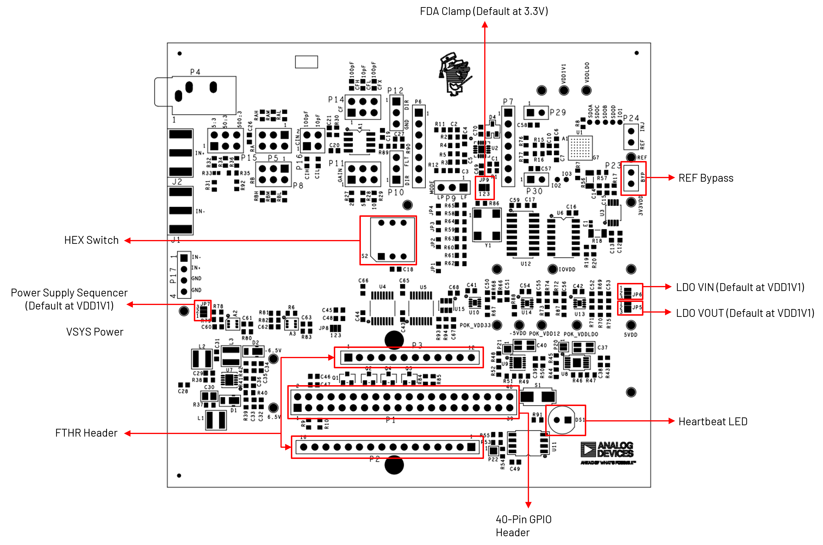
Quick Start
There are numerous combinations of signal sources, signal analyzers, and software that can be used with the ADALM-MMSC. The most straightforward approach to get up and running and establish baseline functionality is to use the ADALM2000 with Scopy. Scopy is a general-purpose IIO-based utility with instrument-specific control panels for various hardware, including the ADALM2000.
Equipment Needed
1x ADALM-MMSC Board (as Device Under Test)
Windows, Mac, or Linux host computer with an available USB port
Signal generator such as the ADALM2000 or similar Alternative signal sources include:
Generators in the audio range work well
A PC sound card with Audacity is another option
Hardware Setup
The hardware setup uses the ADALM2000 (M2K) as the primary signal source for the system, as shown in the image below. In this configuration, the M2K’s waveform generator outputs are connected to the designated input pins on the ADALM-MMSC board, allowing the board to receive and process test signals.
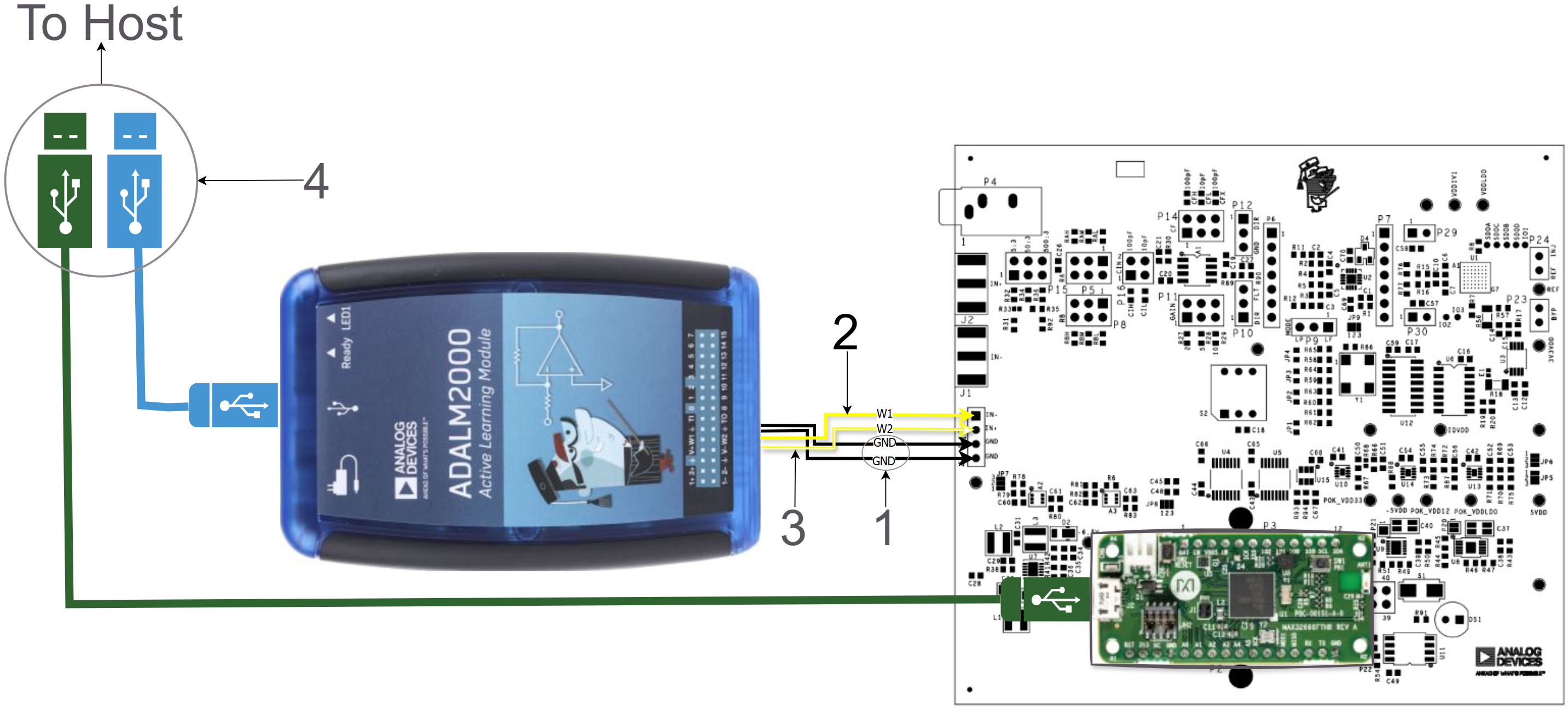
Connect the two black GND wires from the ADALM2000 to the lower two posts of P17 (Pins 3 and 4).
Connect the solid yellow W1 wire from the ADALM2000 to P17 Pin 1.
Connect the striped yellow W2 wire from the ADALM2000 to P17 Pin 2.
Connect both the ADALM2000 and the ADALM‑MMSC to the host computer using two micro‑USB cables.
Set P10 to the lower position (DIR) and P12 to the upper position (DIR). This configuration bypasses the Sallen‑Key filter and applies the inputs directly to the fully differential amplifier.
Software Setup
Requirement:
Download
Scopy: latest version (user guide)
Connect the ADALM‑MMSC to the host computer using a USB‑A to USB‑Micro cable, then open the Scopy GUI.
If you are using the ADALM2000, connect the instrument and allow the calibration process to complete.
From the Scopy home screen, add the ADALM‑MMSC connection by clicking the
+button, as shown in the figure below.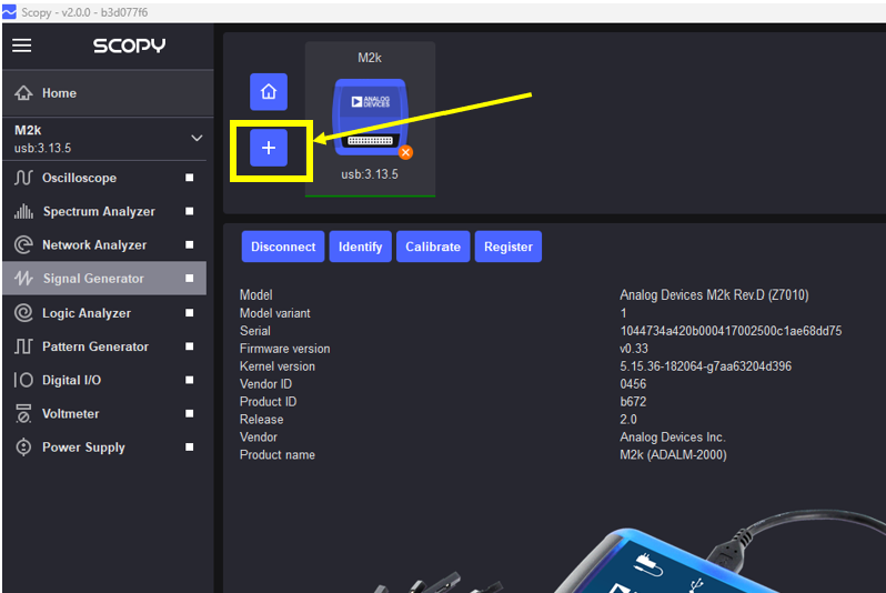
Click the
Scanbutton and select the ADALM‑MMSC serial port. More than one serial port may be listed, depending on the devices connected to the host machine.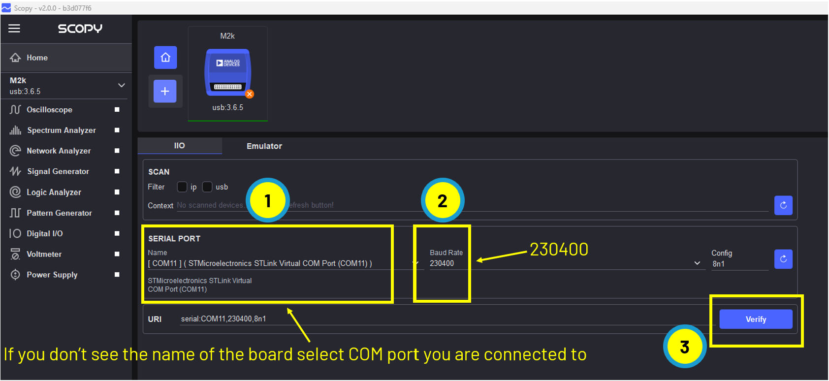
Click
Verify, then clickAdd Device.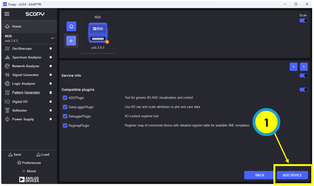
From the Scopy home screen, click
Connect.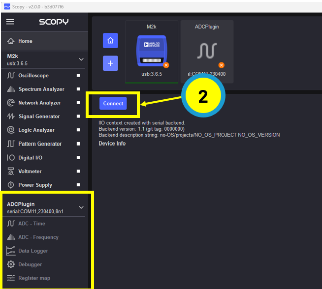
Once connected, Scopy is ready to acquire data from the ADALM-MMSC.
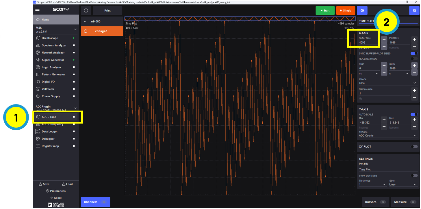
Open the ADC Time panel.
Set the buffer size to 4096 (maximum is 16384, limited by the AD4080 FIFO depth).
Click
Start.
The figure below shows the ADC output when the signal generator is configured as follows:
Channel 1: 1 Vpp, 500 kHz sine wave
Channel 2: 1 Vpp, 50 kHz sawtooth
Refer to the supporting lab exercises and workshop materials for additional experiments.
Firmware Upgrades
Access the ADALM‑MMSC firmware source from the no‑OS repository:
Download the pre‑built firmware binaries from the no‑OS releases page:
The firmware package is provided as
adalm-mmsc.zip.Use the included MAX32625PICO board to upgrade the firmware.
Follow the instructions in the MAX32625PICO firmware images repository to load the MAX32666FTHR‑specific binary:
Connect the 10‑pin ribbon cable between the MAX32625PICO and the MAX32666FTHR board.
Drag and drop the file
adalm-mmsc_maxim_iio_example_max32665.hexinto the DAPLink drive (typicallyD:\orE:\on Windows).Wait for the DAPLink drive to automatically eject, indicating that the firmware upgrade has completed successfully.
Resources
Design & Integration Files
Download
ADALM-MMSC Design & Integration Files
Schematic
PCB Layout
Bill of Materials
Allegro Project
Schematic Errata
The value of R44 is 499 Ohms (not 1.33K as shown in the schematic)
Helpful Links
Support
For questions and more information, please visit the EngineerZone Support Community.