ADRD5161-01Z
BMS module with CANopen CiA 419
Introduction
The ADRD5161-01Z is a battery management/ monitoring system compatible with 3S LiPo battery packs. It communicates via CANopen CiA 419 over 500 kbaud CAN.
The module functions as a state machine with 4 distinct states: Normal State, Charging State, Configure State and Shutdown state. Battery is monitored using the MAX17320 fuel gauge chip. Charging current is handled by MAX77961 charger chip, while the MAX77958 handles power delivery. Current state and specific parameters can be observed on the on-board OLED display. For development and debugging, data is printed to the serial console.
Specifications
20V DC USB standard supply to charge battery
3A maximum Constant Charge Current
Supported Battery: 3S LiPo battery packs
Isolated CAN bus communication, CANopen CiA 419
On-board OLED display with push buttons to control/ navigate menu
Supporting hardware:
MAX32662 Arm Cortex-M4 Processor with FPU-Based Microcontroller (MCU) with 256KB Flash and 80KB SRAM
ADM3053 Signal and Power Isolated CAN Transceiver with Integrated Isolated DC-to-DC Converter
MAX17320 2S-4S ModelGauge m5 EZ Fuel Gauge with Protector, Internal Self-Discharge Detection, and SHA-256 Authentication
MAX77961 25VIN, 3AOUT to 6AOUT, USB-C Buck-Boost Charger with Integrated FETs for 2S/3S Li-Ion Batteries
MAX77958 Standalone USB Type-C and USB Power Delivery Controller
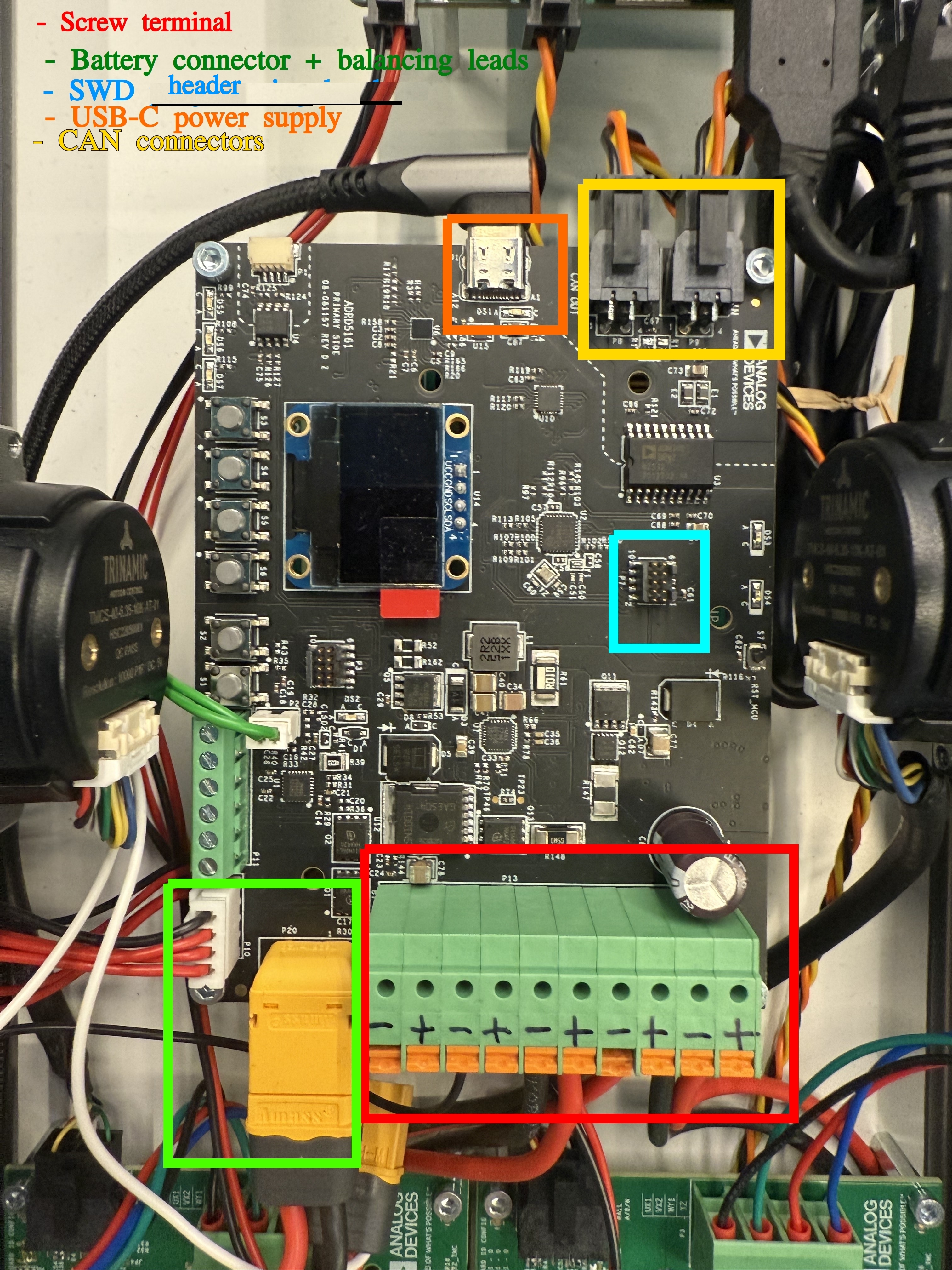
Connections:
Battery connector: XT60 connector and corresponding cable + balancing leads
Charger connection: USB-C cable
CAN, isolated: 2x Custom header described in the Hardware Guide.
Programming/ debugging: SWD header
Power cables to power up other modules: 10 POS terminal block
Required Hardware
ADRD5161-01Z
3S LiPo battery pack with an XT60 connector
USB PD charger, capable of 20V 3A
Optional: MAXPICO (or compatible) debug/ programming probe
System Setup
The module comes with the firmware flashed. MAX17320 and MAX77958 are configured to be compatible with the configuration for Panasonic NCR18650B batteries, with a total capacity 6600mAh.
To set the system up:
connect battery pack and balancing connector
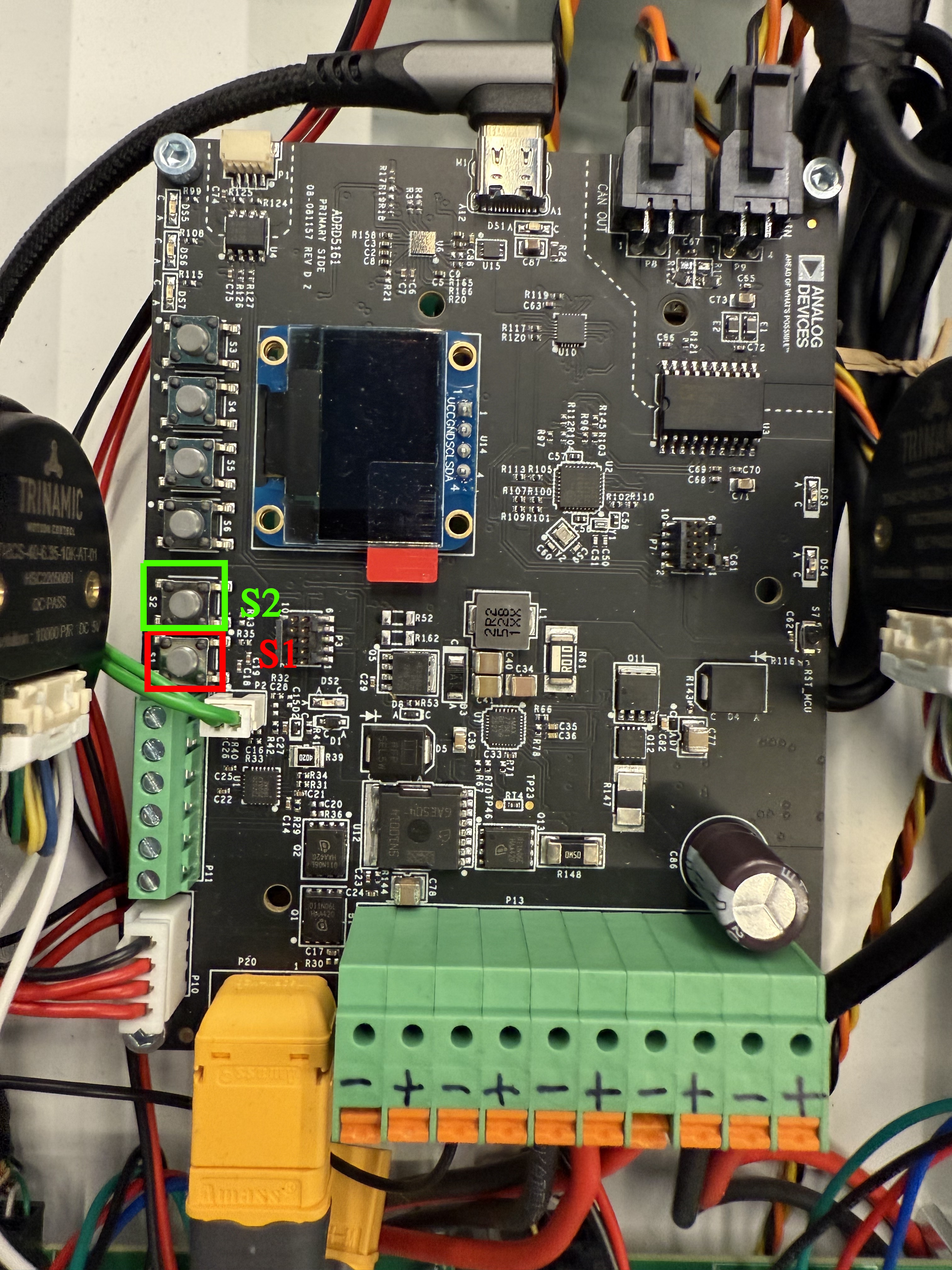
if battery is charged: press S1 button (see image below) to start module
if battery is discharged: plug in USB-C cable connected to 20V/3A capable power supply and module starts on its own
after start, the firmware will go to the Configure state, wait for user input for 10s.
if no user input received, the module will go to either Normal or Charging state, depending on whether the USB-C charging cable is plugged in or not
To poweroff the module, press S2 button. Be mindful when using this feature, as this cuts the power supply to the entire system.
A detailed description of each state and how to control them from the onboard buttons is provided in the Quick Start section.
User Guides
The following user guides are available:
- ADRD5161-01Z Quick Start Guide
- ADRD5161-01Z Hardware Guide
- ADRD5161-01Z Software Guide
- ADRD5161-01Z CANopen reference
- Production Testing
Help and Support
Todo
Support channel