ADRV904x DPD Analysis Tool
The ADRV904x DPD analysis tool can be downloaded from this link. EngineerZone
The v14 of the tool is capable of
Analyzing PA response
Generating DPD models from customer data
Generating CFR / VSWR pulses
Analyzing PA Response
Analyzing the PA response on the feedback loop and ensuring that the PA response is reasonable is critical for good DPD performance. In order to capture the transmitted and observed samples on the feedback loop (open loop DPD response), the user can force a unity gain response on the DPD actuator by configuring a Tx/ORx mean power threshold (such as -1dBFS) for DPD updates prior to enabling the DPD tracking calibration.
The following code snippet shows how to configure the DPD to engage the actuator in bypass mode (output = input)
def dpdRobustnessConfigSet(channel = adi_adrvgen6_TxChannels_e.ADI_ADRVGEN6_TX0):
    dpdStabilityConfig = adi_adrvgen6_DfeAppCalDpdStabilityCfg_t()

    #Define Fault Conditions for Mean Tu Power. Skip DPD updates if DPD actuator input power is higher than -1dBFS
    #dpdStabilityConfig.bit[0] = adi_adrvgen6_DfeAppCalDpdStabilityBitCfg()
    dpdStabilityConfig.bit[0].LTGT = 0 #Select Less Than Switch
    dpdStabilityConfig.bit[0].threshold0 = -100
    dpdStabilityConfig.bit[0].threshold1 = -3700
    dpdStabilityConfig.bit[0].persistentCnt = 10

    #Configure Recovery Actions

    #Skip LUT updates if mean Tu power(DPD actuator input power) exceeds threshold0 configured above
    dpdStabilityConfig.error[0].mask = 0x0001#0x01c1  #int(adi_adrvgen6_DfeAppCalDpdStability_e.ADI_ADRVGEN6_DFE_APP_CAL_DPD_DIRECT_EVM) | int(adi_adrvgen6_DfeAppCalDpdStability_e.ADI_ADRVGEN6_DFE_APP_CAL_DPD_INDIRECT_ERROR)
    dpdStabilityConfig.error[0].actionWord = 0x0001 #int(adi_adrvgen6_DfeAppCalDpdRecoveryAction_e.ADI_ADRVGEN6_DFE_APP_CAL_DPD_SKIP_UPDATE)

    ret = adrv904x.dfe_dpd.DpdStabilityCfgSet(int(channel), dpdStabilityConfig)
After setting up the actuator in bypass mode via ** DpdStabilityCfgSet( )** and enabling the DPD tracking calibration via DfeTrackingCalsEnableSet() API, the user can now proceed to dump the DPD open loop data for PA response analysis by executing the code snippet shown below.
#Utility Function to write data to a file
def fileDataWriter(fileHandle, numSamples, iData = None, qData = None):
    if  (len(iData) != 1 and len(qData) != 1):
        print "Writing to filename:", fileHandle
        dataFile = open(fileHandle, "w")
        for ii in range(0,numSamples):
            iSample = str(iData[ii])
            qSample = str(qData[ii])
            dataFile.write(iSample+"\t"+qSample+"\n")
        dataFile.close()
#Example code snippet to dump capture buffer data

def dpdCaptureDataDump(channel = adi_adrvgen6_Channels_e.ADI_ADRVGEN6_CH0,dir = "D:\\Misc\\TestData\\"):
    capBufData = adi_adrvgen6_DfeAppDpdCaptureData_t()
    capBufData.txCaptureData = adi_adrvgen6_DfeAppDpdCaptureDataRow_t()
    capBufData.txAltCaptureData = adi_adrvgen6_DfeAppDpdCaptureDataRow_t()
    capBufData.orxCaptureData = adi_adrvgen6_DfeAppDpdCaptureDataRow_t()
    adrv904x.dfe_dpd.DfeDpdCaptureDataFromBufMemGet(channel,capBufData)
    fileDataWriter(dir+"_Tu.txt", capBufData.txAltCaptureData.dpdCaptureSampleArrSize, capBufData.txAltCaptureData.dpdCaptureDataI, capBufData.txAltCaptureData.dpdCaptureDataQ)
    fileDataWriter(dir+"_Orx.txt", capBufData.orxCaptureData.dpdCaptureSampleArrSize, capBufData.orxCaptureData.dpdCaptureDataI, capBufData.orxCaptureData.dpdCaptureDataQ)

if __name__ == '__main__':

    # Connect IronPython to command server
    platform = connect()

    # Get device objects
    board = platform.Boards[0]
    ad9528Dev = board.DeviceGet('ad9528', 0)
    fpgaDev = board.DeviceGet('fpga', 0)
    adrv904x = board.Adrvgen6DeviceGet(0)

    # Your code goes here!
    dpdCaptureDataDump()
    print 'Data Buffer Capture complete!'
A batch of 4096 samples of Tu and ORx data is written to a .txt file in tab separated IQ format.
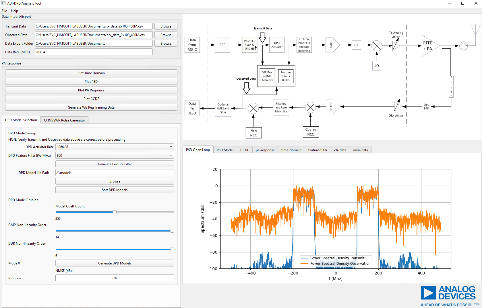
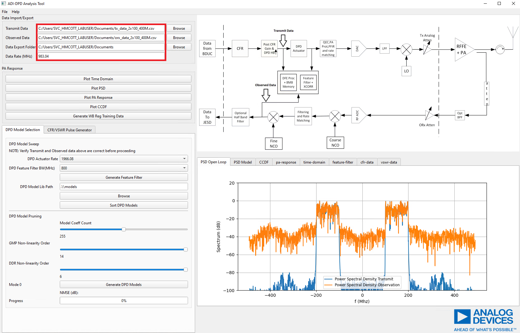
Once you have the 4096 samples logged, the Tu and ORx data can be loaded to the ADI DPD analysis tool, by specifying corresponding Tu and ORx data files as well as an output directory for data to be saved to. This is shown in the figure below.
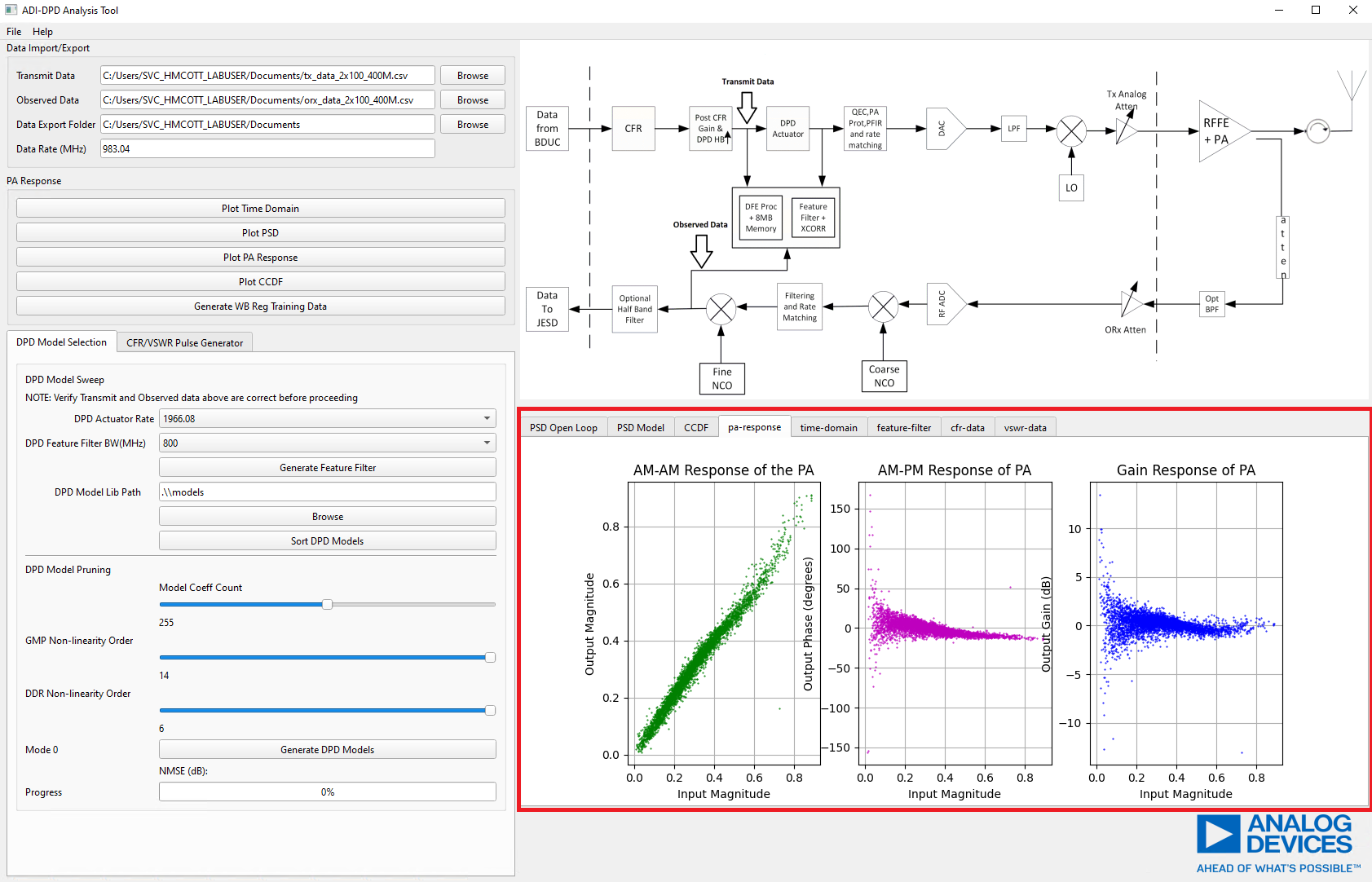
The PA responses (Time domain, Power Spectral Density, CCDF, AM/PM and Gain response) can be plotted in a tabbed window shown below. Plotting a response will automatically select the tab corresponding to the plotted data. The user may also click on a tab to view the specific data plot.
Identifying an Optimal DPD Model
After validating that the PA response is reasonable as shown in the previous section, the user may proceed to identifying an optimal model for their Power Amplifier based on the open loop PA response seen in the previous section.
Sweeping DPD Models
ADI provides two methods of model selection: existing model sweep/search or a
model pruning optimization. A DPD model library as part of the ADRV904x
Software Package is provided in the default model sweep directory shown below.
Also, attached here
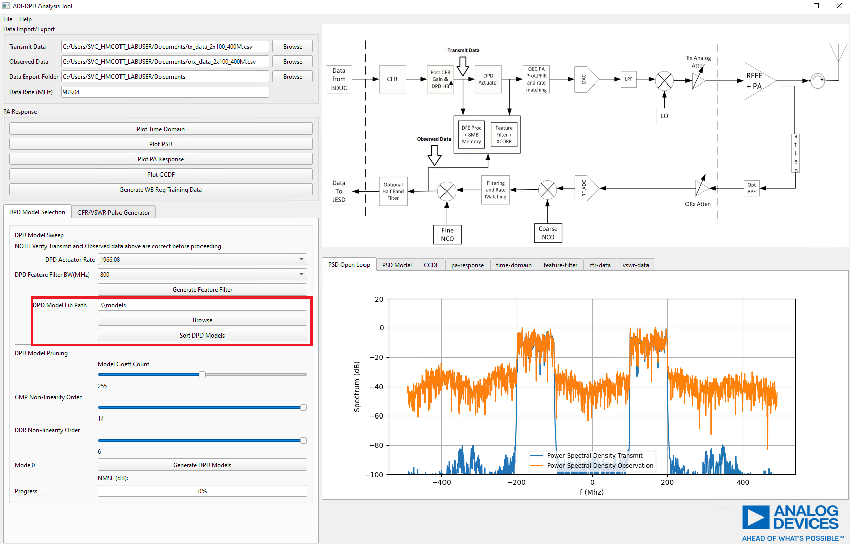
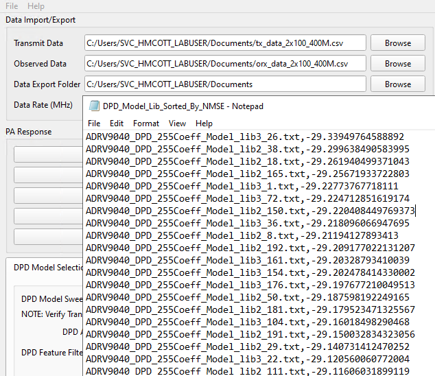
The user can then sort the DPD models by pressing the “Sort DPD Models” button. A loading bar will update the progress of the sweep, before outputing a text file with the DPD models, which are sorted by NMSE. The PSD of the model results will be shown in the PSD Model tab of the figure viewer.
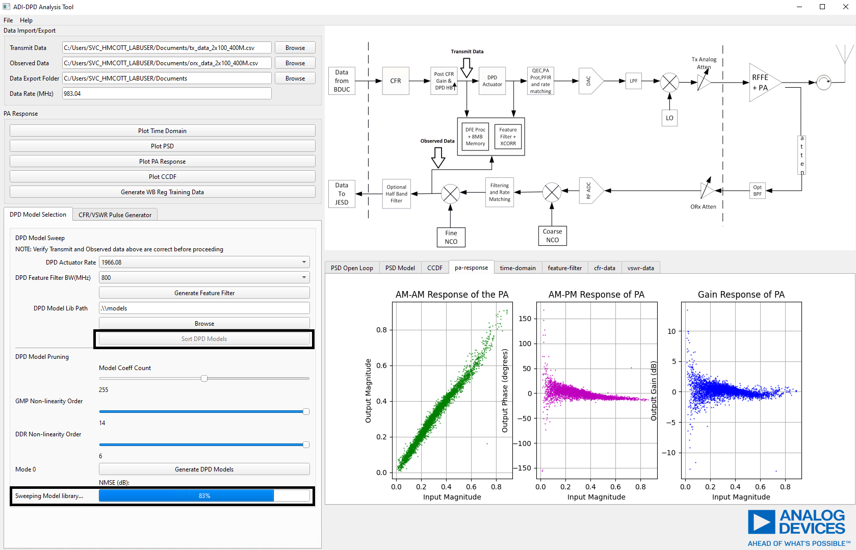
An example of the output file is shown below.
Pruning DPD Models
Model pruning optimization can be conducted by selecting a model coefficient/feature limit using the “Model Coeff Count” slider. 255 coefficients can be selected for default operation and 510 for partial DPD operation. A selection of 255 coefficients is recommended.
Other parameters, such as nonlinearity order of the DPD model basis functions can be specified. It is recommended that the user uses the default parameters shown below.
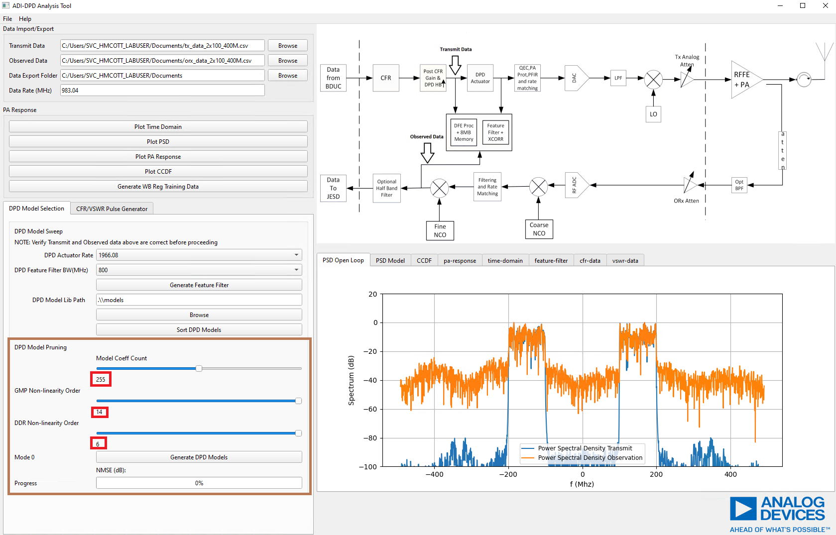
Pressing the “Generate DPD Models” button will begin the model optimization, which may take up to 10 minutes to complete. The progress bar will update for each of the eight models created. The PSD of the model results will be shown in the PSD Model tab of the figure viewer. Models are output to the ‘Data Export Folder’ under the subfolder ‘models’.
Documentation for the GUI and its features can be easily accessed through the help toolbar option.