SDP-H1 quick start
The evaluation board can also be controlled with the EVAL-SDP-H1 controller board and the ACE software, without any FPGA or Linux system. This is the path for evaluating DC precision and static DAC behavior directly from a PC.
Installing ACE
Download and run the latest ACE installer, which also installs the drivers for the SDP-H1.
Open ACE, click Plugin Manager on the left-hand menu, go to Available Packages, select
Board.AD35X2R, and click Install Selected. The plugin moves to Installed Packages.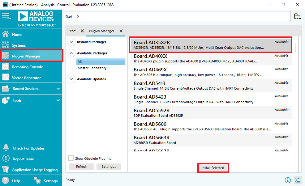
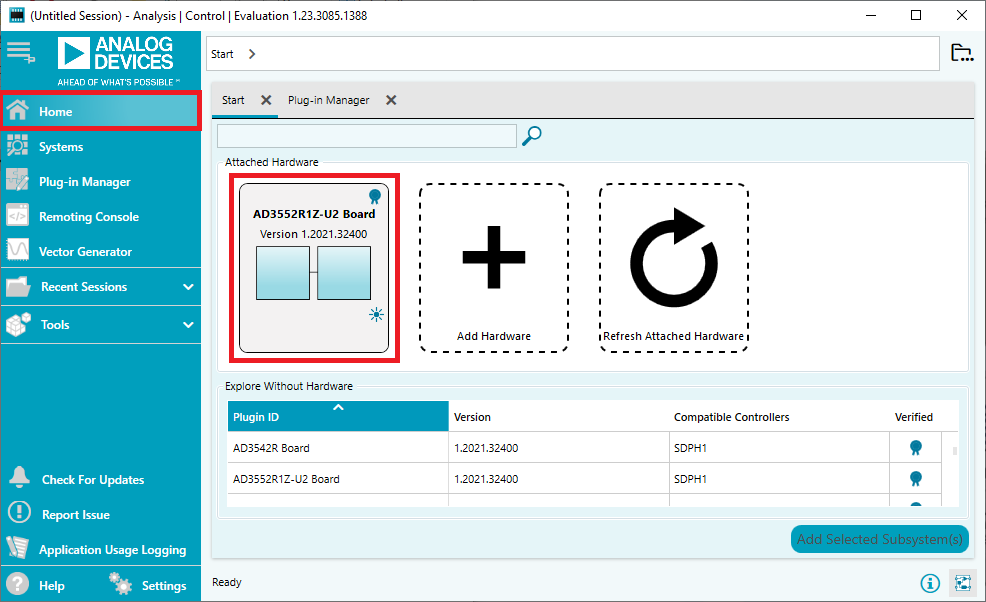
Click Home on the left-hand menu. If the board is connected it appears in Attached Hardware. If you don’t have the board yet, you can still explore the plugin by double-clicking the desired board in the Explore Without Hardware list.
Connecting the board (SDP-H1)
Set all links to default positions (see link options table above).
Plug the EVAL-AD3552R onto the SDP-H1 controller board.
Connect the wall-plug power supply to the SDP-H1 DC jack. Power LEDs turn green.
With ACE running, connect the USB cable between the SDP-H1 and the PC. The board appears in Attached Hardware - double-click its icon to open the Board View.
ACE plugin views
ACE organizes control across several linked views:
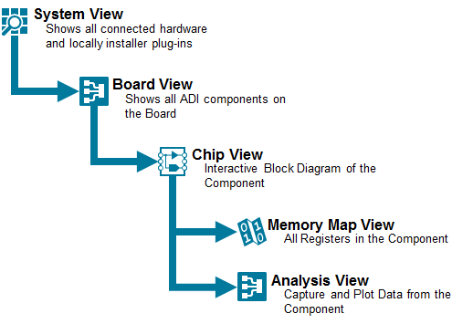
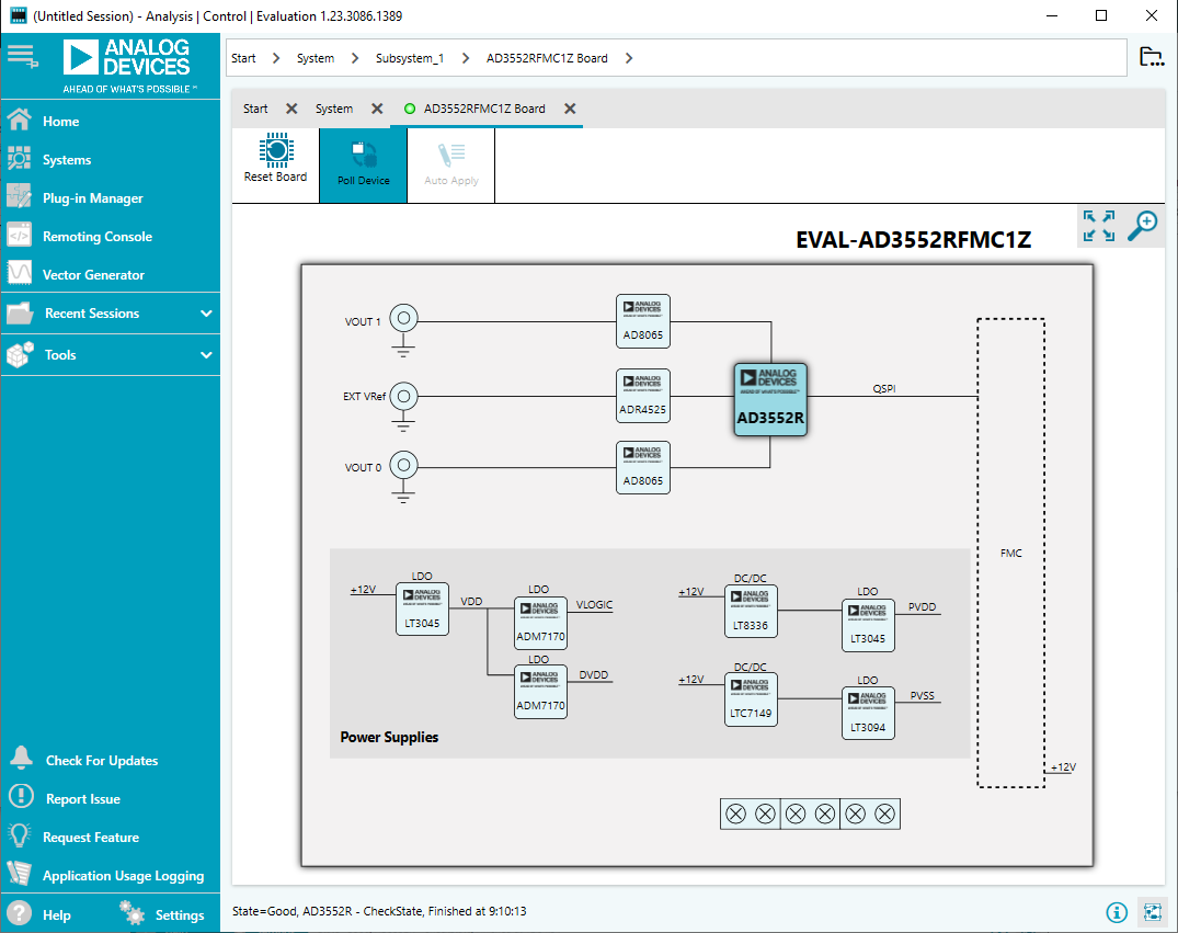
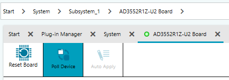
Board View - simplified diagram of the evaluation board. Use Poll Device to verify connectivity and Reset Board to power cycle the evaluation board. Double-click the AD3552R block to open the Chip View.
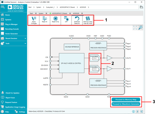
Chip View - internal block diagram of the AD3552R with editable DAC output register fields. Buttons: Apply Changes, Read All, Reset Chip, Diff, Software Defaults, Memory Map Side-By-Side.
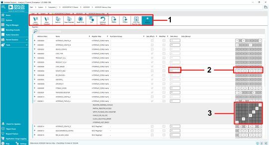
Memory Map View - complete register map displayed as a list of registers or bit fields. Supports sorting, searching, individual or bulk read/write, CSV export and import.
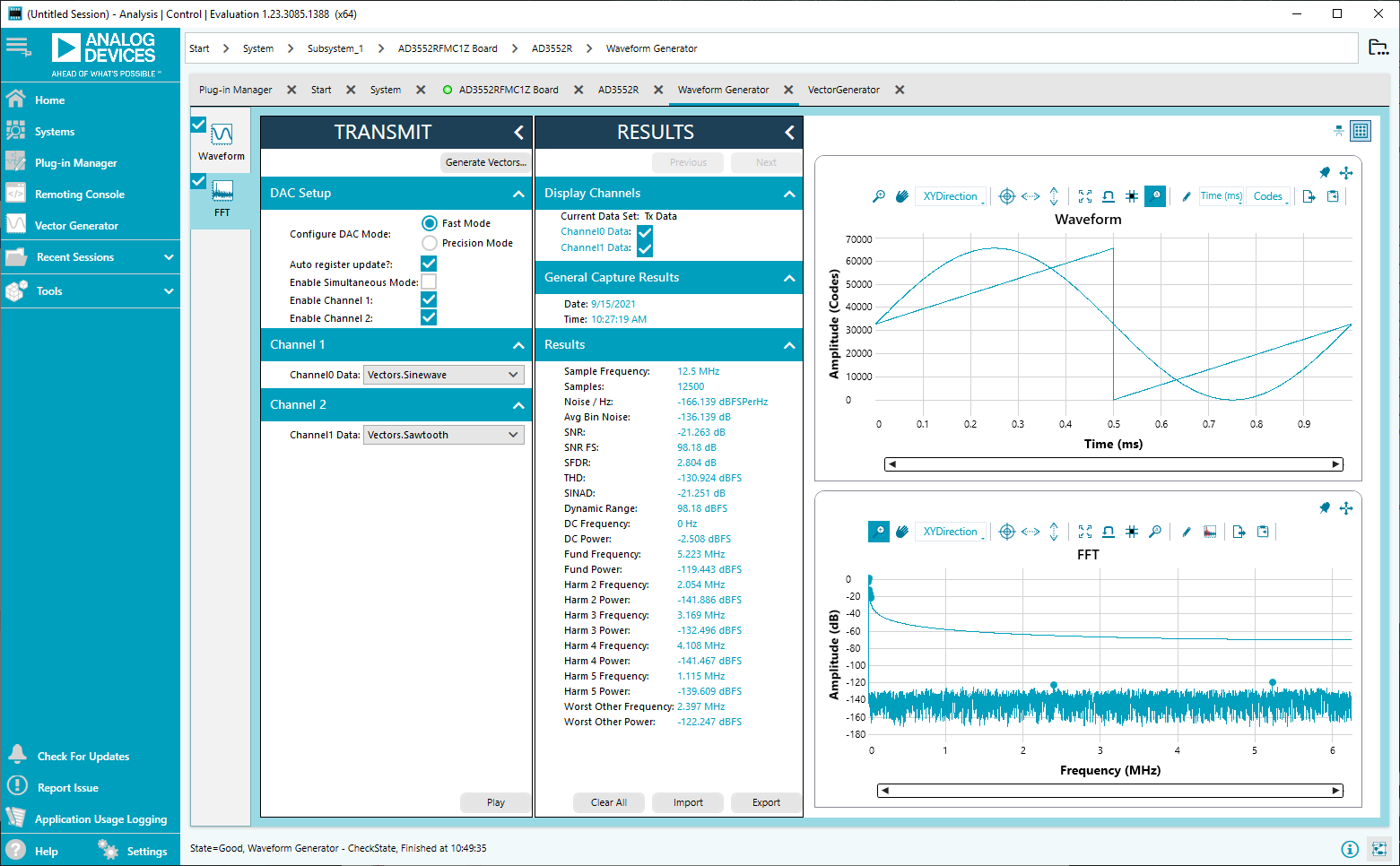
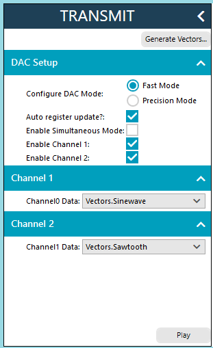
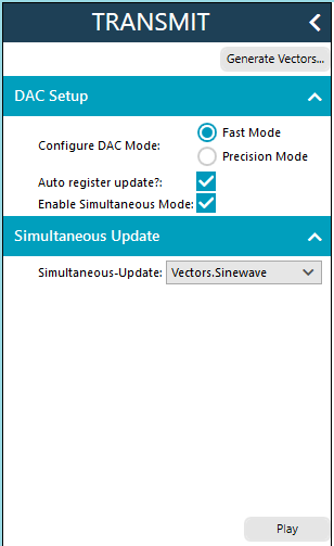
Waveform Generator View - assign waveforms to channels and start or stop playback. Key controls: DAC Mode (Fast 16-bit or Precision 24-bit), Enable Simultaneous Mode, Enable Channel 1/2, Play. The EVAL-AD3552R LED is blue during playback and green when stopped.
Maximum update rates (AD3552R with SDP-H1):
Fast Mode (16-bit)
Precision Mode (24-bit)
Dual channel
12.5 MUPS
8.33 MUPS
Single channel / Simultaneous
25 MUPS
16.66 MUPS
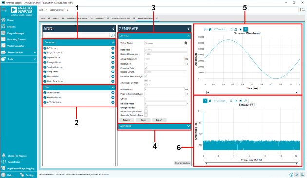
Vector Generator View - define or load waveforms (DC, single tone, square, triangle, sawtooth, chirp, noise, multi-tone, or from file). Parameters: Vector Name, Desired Frequency, Attenuation (dB), Relative Phase. Includes time-domain preview and FFT window.
Creating a dual waveform (step-by-step)
From the start page, double-click the board icon to open the Board View.
Double-click the AD3552R block to open the Chip View.
Click Proceed to Memory Map and set the desired output range in
CH0_CH1_OUTPUT_RANGE(e.g.,0x33for ±10 V). Click Apply All.Open the Vector Generator and create a 1 kHz sine wave and a 1 kHz sawtooth wave.
Go back to the Chip View, click Proceed to Waveform Generator, select Fast Mode, enable both channels, assign the waveforms, and click Play.
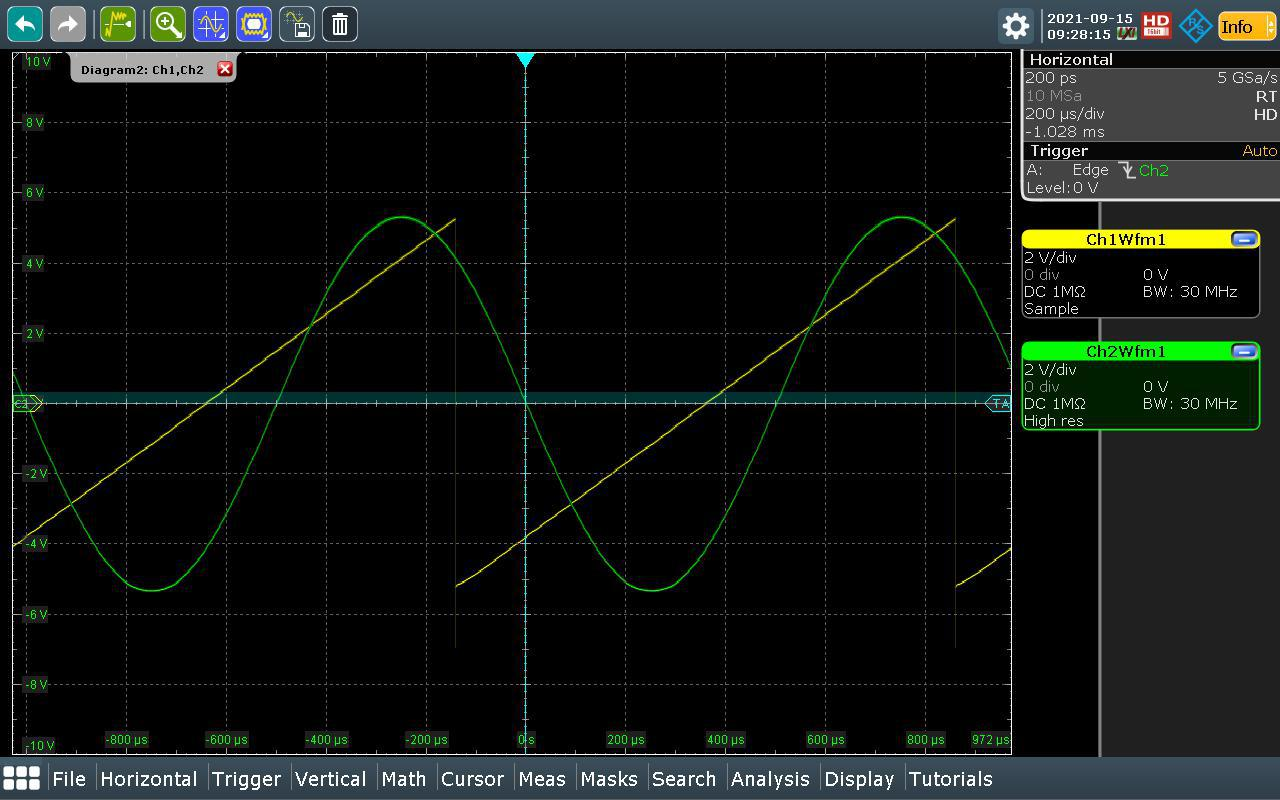
Figure 13 Simultaneous dual waveform output on oscilloscope.
If Auto Register Update is unchecked, configure the following registers before pressing Play:
Register |
Setting |
|---|---|
|
Set stream length (see table below) |
|
Set |
|
Set |
Stream length values by mode:
Fast Mode (16-bit) |
Precision Mode (24-bit) |
|
|---|---|---|
Single channel / Simultaneous |
2 |
3 |
Dual channel |
4 |
6 |
Unsupported features in ACE plugin (v1.2021.38200)
The following features are not yet supported; ACE notifies when an update is available:
DAC output range selection and customization
CRC checking
Amplitude and offset control in waveform generation (scaling only via Attenuation in dB; offset fixed to mid-scale)
Using the LDAC line to update the DAC output