Quick start
The quick start guide provides step-by-step instructions on how to perform an initial system bring-up for the EVAL-AD9213-DUAL-EBZ evaluation board on the supported FPGA development board. This guide covers Synchronized 10G Mode and Interleaved 20G Mode for data capture and visualization in IIO Oscilloscope and VisualAnalog.
Supported carriers
FPGA board |
AD9213-DUAL-EBZ |
|---|---|
Intel Stratix 10 SX SoC Development Kit (1SX280HU2F50E1VGAS) |
FMC+ |
Supported environments
FPGA board |
HDL |
Linux software |
No-OS software |
|---|---|---|---|
Intel Stratix 10 SX SoC |
Yes |
Yes |
— |
Hardware setup
The AD9213-DUAL-EBZ connects to the Intel Stratix 10 SX SoC Development Kit via the two FMC+ connectors. The following connections and equipment are required:
USB: Connect the Mini-USB port (JTAG) and the Micro-USB port (serial, 115200 baud 8N1) to the host PC.
Power: Two separate power adapters are needed - one for the Intel Stratix 10 SX SoC board and a 12 V adapter for the AD9213-DUAL-EBZ.
Clock reference: A 500 MHz differential clock signal is required. Use a differential signal generator such as the AD-SYNCHRONA14-EBZ directly, or a single-ended signal generator combined with a balun to produce the differential output.
Test signal (for dual-channel capture): Connect a signal generator through a band-pass filter into an RF power splitter, then route the two outputs via phase-matched coaxial cables to the AD9213-DUAL-EBZ analog inputs.
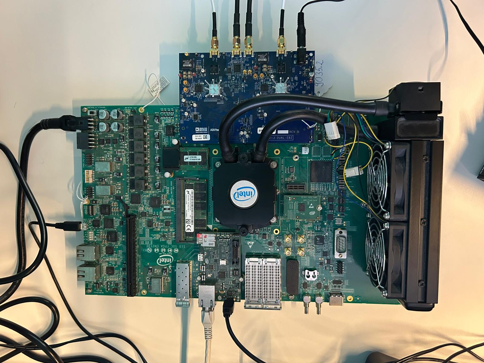
Figure 1 AD9213-DUAL-EBZ and Intel Stratix 10 SX Board - Setup
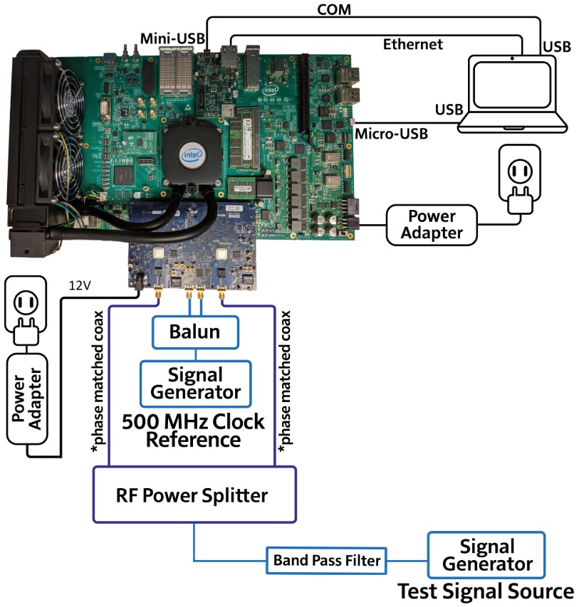
Figure 2 AD9213-DUAL-EBZ and Intel Stratix 10 SX Board - Typical Setup