The AD-GMSL792MIPI-EVK is a compact and cost-effective evaluation kit
that converts dual GMSL3/2 camera links into MIPI CSI-2 for modern SoC
platforms. Built around the MAX96792 dual deserializer, it delivers a
robust bridge for vision workloads across automotive and industrial
applications.
To simplify wiring and speed up integration, the board supports a wide
range of image sensors and integrates Power over Coax (PoC) so data and
power travel on a single coaxial cable. The kit also includes ready-to-use
reference software with device-tree overlays and Linux images for
supported camera setups, helping you go from power-up to first frames
fast.
Engineered for quick results, it maintains reliable video over cable up
to 15m length with PAM-4 GMSL3 at 12 Gbps and remains backward
compatible with GMSL2 at 6 Gbps or 3 Gbps. A bidirectional I²C control
channel streamlines camera configuration while the small footprint and
flexible mounting make it ideal for rapid GMSL3 camera prototyping.
Features
Dual GMSL3/2 deserializer based on MAX96792
2 × MIPI CSI-2 output connectors
(each up to 4 lanes D-PHY at 2.5 Gbps/lane)
2 × GMSL input connectors over 50Ω coax
Power over Coax implementation, 12V, 1.2A total output
USB-C 5V input or 6-pin header alternative power input
Compatible with NVIDIA Jetson, Raspberry Pi, and AMD SoC
platforms
Independent MIPI CSI-2 connector operation available
Small form factor, mounting compatible with Raspberry Pi
Applications
Advanced driver assistance systems (ADAS)
Mobile and mounted robotics
Autonomous vehicles and automotive cameras
Outdoor machines and industrial equipment
Smart and flexible manufacturing systems
Security and surveillance systems
Industrial automation and machine vision
Specifications
Parameter
Specification
GMSL3/2 Inputs
2 channels, 12Gbps / 6Gbps / 3Gbps
configurable
MIPI CSI-2 Outputs
2 × 4-lane ports, up to 2.5Gbps per lane
Power Input
USB-C or via the 6-pin connector, 5V ±5%
PoC Output
12V, 1.2A total
Cable Length
Up to 15 meters
Key Components
MAX96792A, LTC3303
System Architecture
Figure 2 AD-GMSL792MIPI-EVK System Architecture
Forward Path (Camera to SoC):
Camera sensor captures image data
GMSL3/2 serializer converts parallel data to serial stream
Data transmitted over coaxial cable at the specified data rate
MAX96792A deserializer receives GMSL3/2 data
Data converted to MIPI CSI-2 format
MIPI CSI-2 output connects to SoC platform
Reverse Path (SoC to Camera):
Control commands originate from SoC platform
I2C/control signals processed by MAX96792A
Commands transmitted over GMSL3/2 reverse channel at 187.5Mbps
Serializer receives and processes control commands
Commands applied to camera sensor and peripherals
Power Distribution:
5V input power received via USB-C connector or via the 6-pin connector
LTC3303 regulator converts 5V to required board voltages: 1.8V and 1.2V
PoC circuit using LT8337JV generates 12V output for camera power
Power delivered to camera through coaxial cable
What’s Inside the Box
AD-GMSL792MIPI-EVK evaluation board
ESW-103-44-G-D 6POS dual row connector
05-22-D-0050-A-4-06-4-T FFC 22POS 50 mm cable
FF3025-CO102-022 FFC 22POS 102 mm cable
8 x screws
4 x 21 mm standoffs
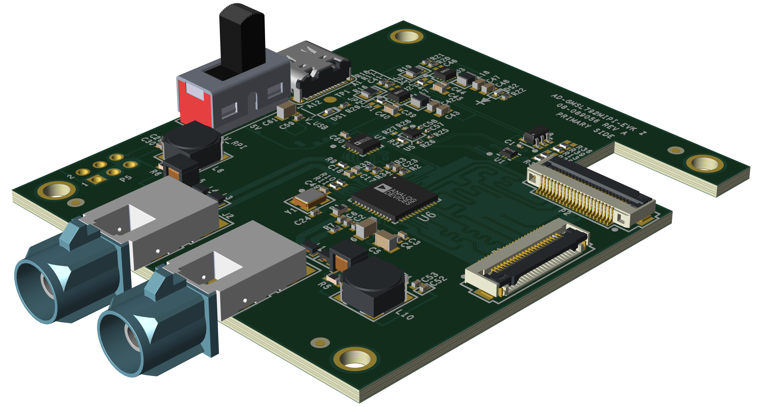
Components and Connections
Primary Side
DS1 LED - indicates 5V USB-C input
DS2 LED - indicates 1.8V rail
P5 Connector - alternative 5V input and Raspberry Pi shield
(same nets as Raspberry Pi’s GPIOs)
Compatible SoC development platform (Jetson, Raspberry Pi, AMD)
GMSL3/2 camera with serializer (for example, AD-GMSL793MIPI-EVK)
Coaxial cable (50Ω)
MIPI CSI-2 FFC/FPC cable (22-pin)
USB-C power supply (5V, minimum 2A)
Multimeter (for verification)
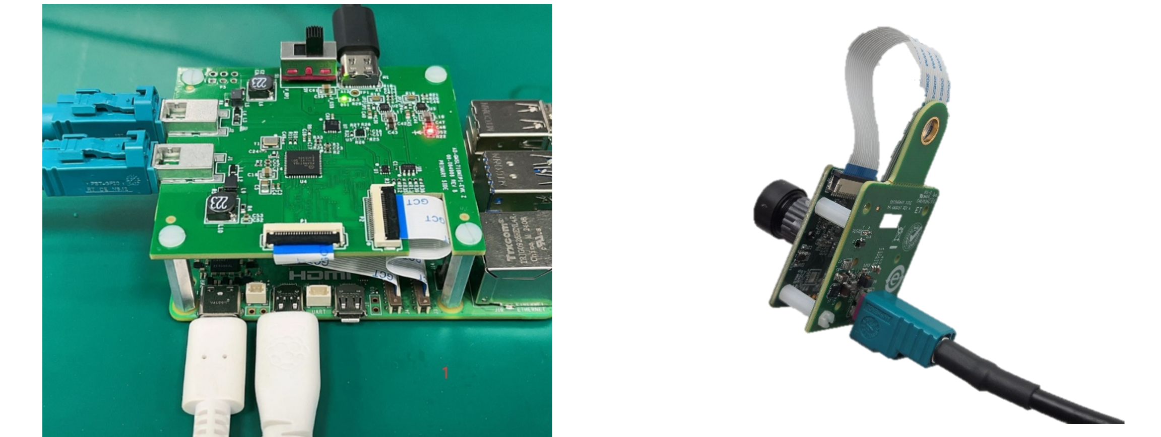
Figure 3 AD-GMSL792MIPI-EVK Hardware Connection
Power System Verification
Ensure all power sources are disconnected.
Verify USB-C power supply specifications (5V ±5%).
Place the switch in the first (upper) position.
Connect USB-C power cable to board.
GMSL3/2 Camera Connection
Connect GMSL3/2 camera to coaxial cable.
Verify cable specifications (50Ω coax).
Connect cable to any of the GMSL connectors.
Ensure secure mechanical connection.
SoC Platform Connection
Select appropriate MIPI CSI-2 FPC cable.
Connect board MIPI output to SoC platform CSI-2 input.
Verify pin compatibility and orientation.
Secure cable connections.
Power-Up Sequence
Apply power via USB-C connector.
Verify led illumination.
Check for GMSL3/2 link lock.
Monitor MIPI activity indicators.
Sample Measurements and Expected Readings
Parameter
Expected Reading
Supply voltage at USB-C input
5.0V ±0.25V
PoC output voltage
12.0V ±0.5V
PoC output current
Up to 1.2A
Link lock time
< 100ms typical
MIPI CSI-2 output levels
MIPI D-PHY v1.2 compliant
Software
The GMSL software package provides comprehensive driver support
and configuration tools for integrating GMSL3/2 cameras with
popular SoC platforms. The software includes device tree configuration
and kernel drivers.
Analog Devices will provide limited online support for anyone using the
reference design with Analog Devices components via the
EngineerZone reference designs forum.
It should be noted that the older the tools’ versions and release branches are,
the lower the chances to receive support from ADI engineers.