ADRD5161-01Z Quick Start Guide
Required Hardware
ADRD5161-01Z
3S LiPo battery pack with an XT60 connector
USB PD charger, capable of 15V/20V, 3A (min)
CAN cable
Optional: MAXPICO (or compatible) debug / programming probe
Getting Started
The ADRD5161-01Z module comes with the state machine firmware already flashed. MAX17320 and MAX77958 are already configured for Panasonic NCR18650B batteries, with a total capacity 6600mAh.
Connect the battery pack and balancing leads to the BMS module
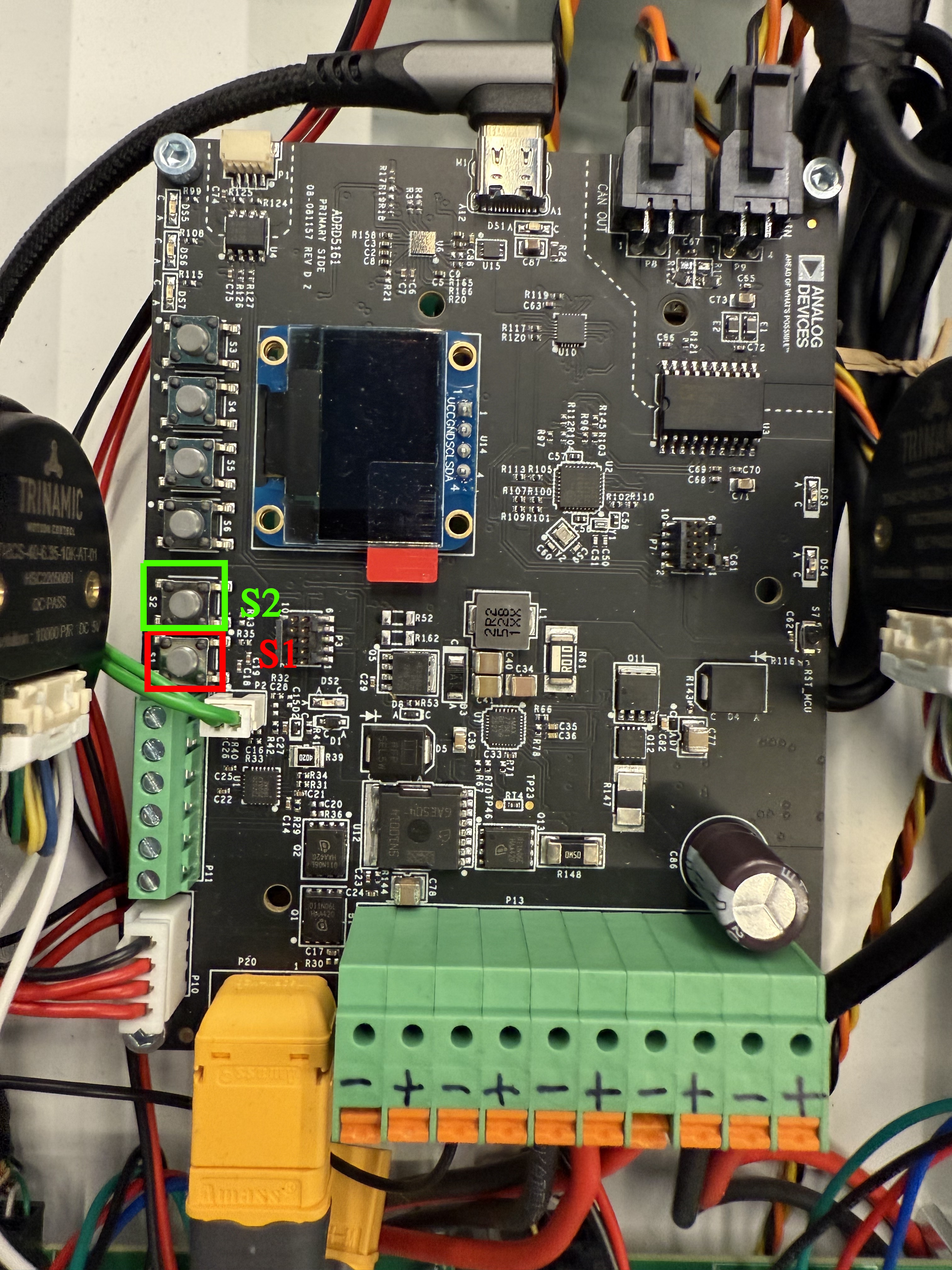
In order to start the module, after the battery is connected, S1 needs to be pressed.
To poweroff the module, press S2.
If the battery pack requires charging, plug in the USB-C cable, connected to 20V/3A capable power supply. In this case, the module will power up automatically.
After powering up, the module will enter the Configure State, where it waits for user input to be triggered. If no user input is received, the module will use default values.
Depending on whether or not the USB-C cable is plugged in, the module will enter either the Normal or the Charging State.
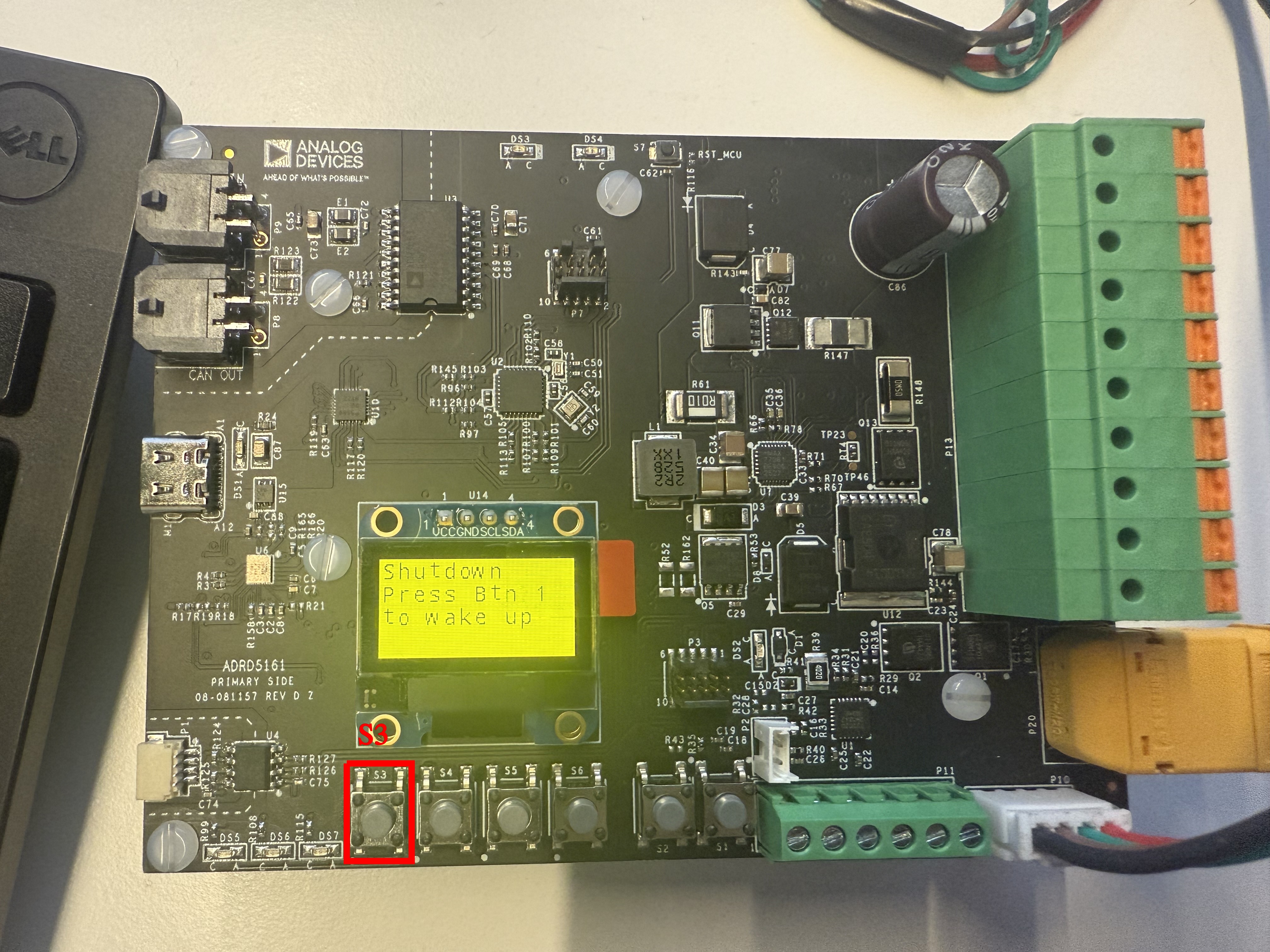
The Shutdown state cuts the power to the CAN Transceiver and the rest of the system, while keeping the BMS module powered on.
Firmware flashing
Hardware Requirements:
MAX32625PICO or similar DAPLINK programmer + cable
Software Requirements:
MaximSDK installed
ZephyrSDK installed
Zephyr Workspace configured
# Replace /MaximSDK/ with the path to MSDK
$ west flash --openocd-search /MaximSDK/Tools/OpenOCD/scripts/ --openocd /MaximSDK/Tools/OpenOCD/openocd
Complete build instructions for the firmware, required tools and Zephyr workspace configuration are provided in the ADRD5161-01Z Software Guide.
BMS State Machine Description and GUI control
Configure State - Battery Pack Configuration
The first step required when plugging in a new battery pack is configuring the BMS parameters for it. This may be done via the GUI on the BMS board. Analog Devices Inc. recommends using the battery configuration provided, which was already tested.
However, the Configure state allows for the following parameters to be configured:
FullCapacity - with a maximum of 6600mAh
Constant Charge Current: 100mA < CC Current < 3A
Charge Termination Voltage: 10.2V < Vt < 12.6V
At power up, the module will go to the Configure State. To trigger user configuration, press S4 button. Then, to increase the value for each parameter, the same button needs to be pressed(S4). To decrease, S5 must be pressed. When satisfied with the value, and to move on to the next parameter, press S6. The buttons and their significance for the Configure State are highlighted in the image below.
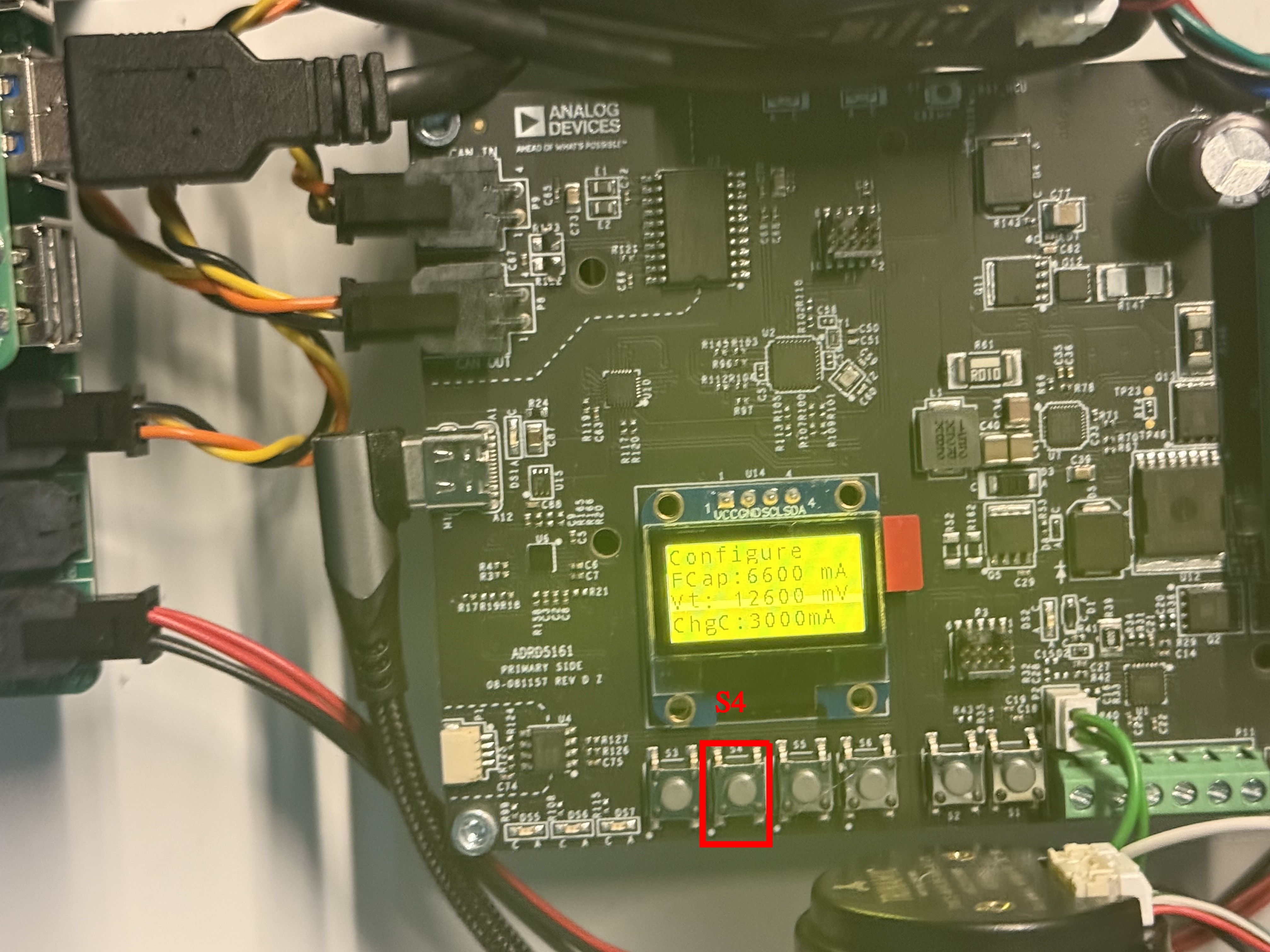
Figure 2 ADRD5161-01Z startup screen and navigation button S4.
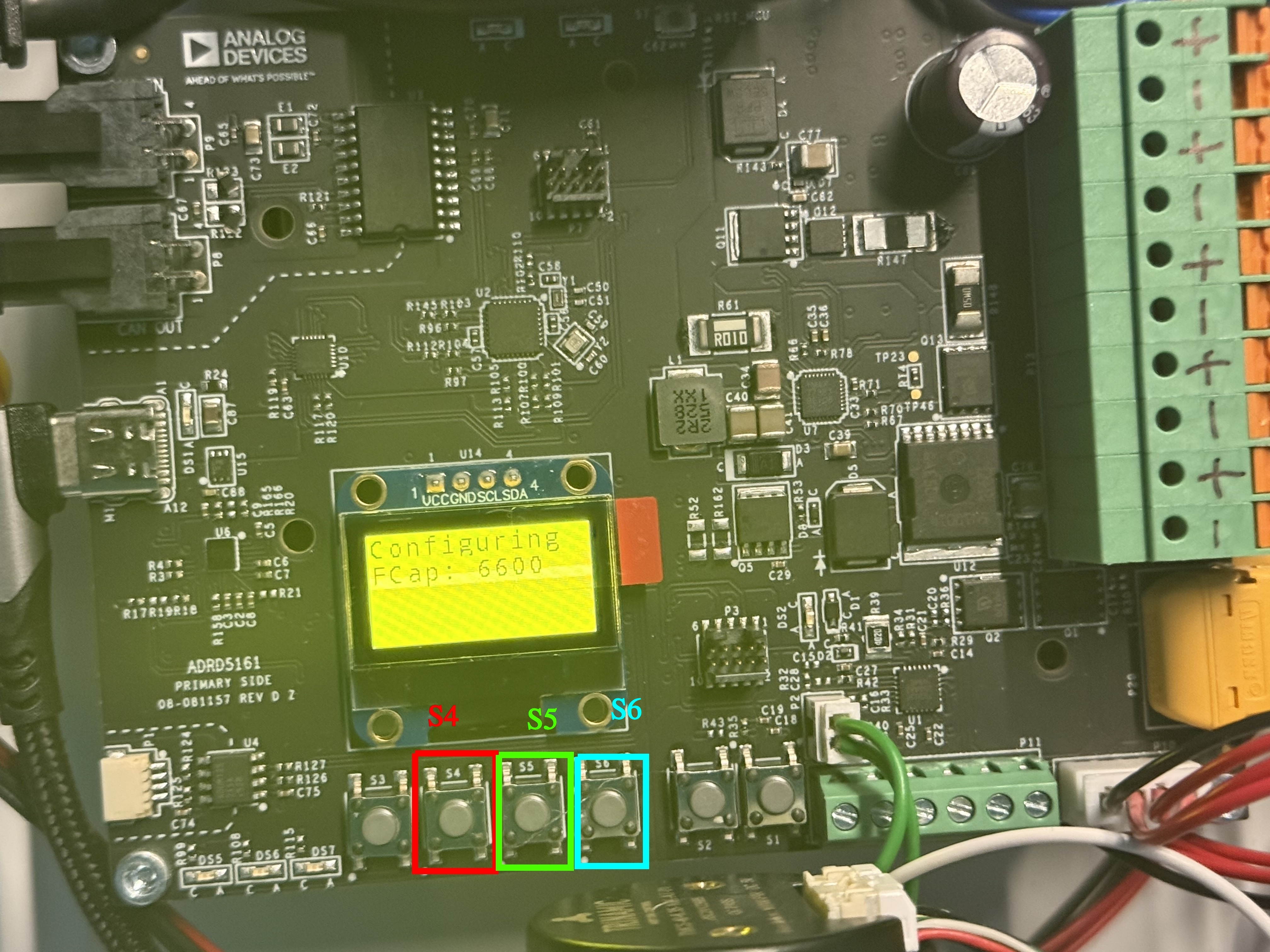
Figure 3 ADRD5161-01Z startup screen and navigation buttons S4, S5, S6.
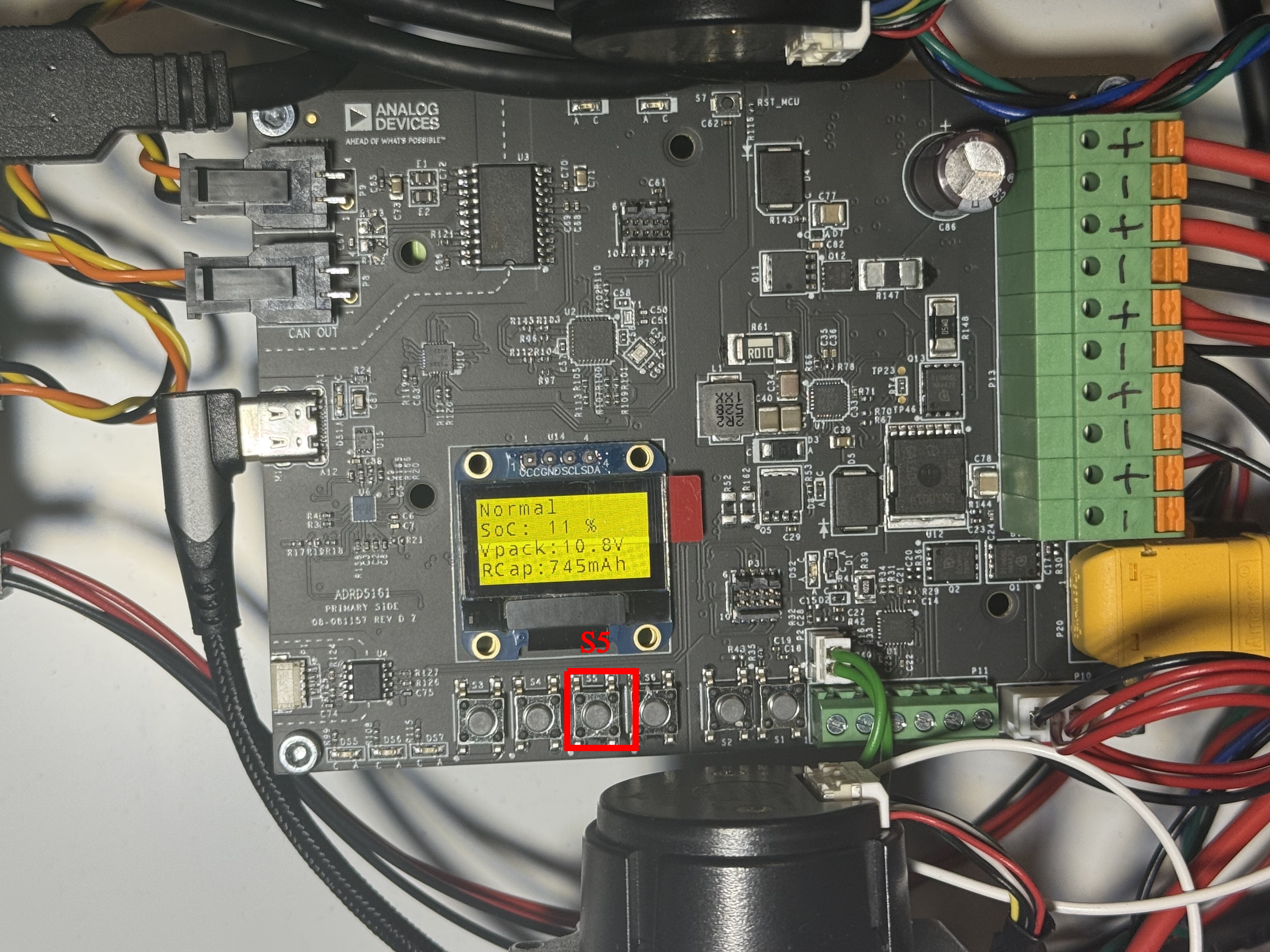
Normal State
When in the Normal State, the ADRD5161-01Z board enables the power supply towards the system( motor control boards, localization boards) The CAN Transceiver is powered up here as well, thus enabling CAN communication. This state displays the following parameters, both on the screen in the serial console:
State of Charge - SoC - %
Pack Voltage - mV (serial console) & V on display
Cell1, Cell2, Cell3 Voltage - mV
Current - mA
Fuel Gauge Temperature - °C
Remaining Capacity - mAh
Full Capacity - mAh
Time to empty - minutes
Charging Current - mA
Temperature (from onboard Temperature sensor) - °C
To navigate OLED display, press S5.
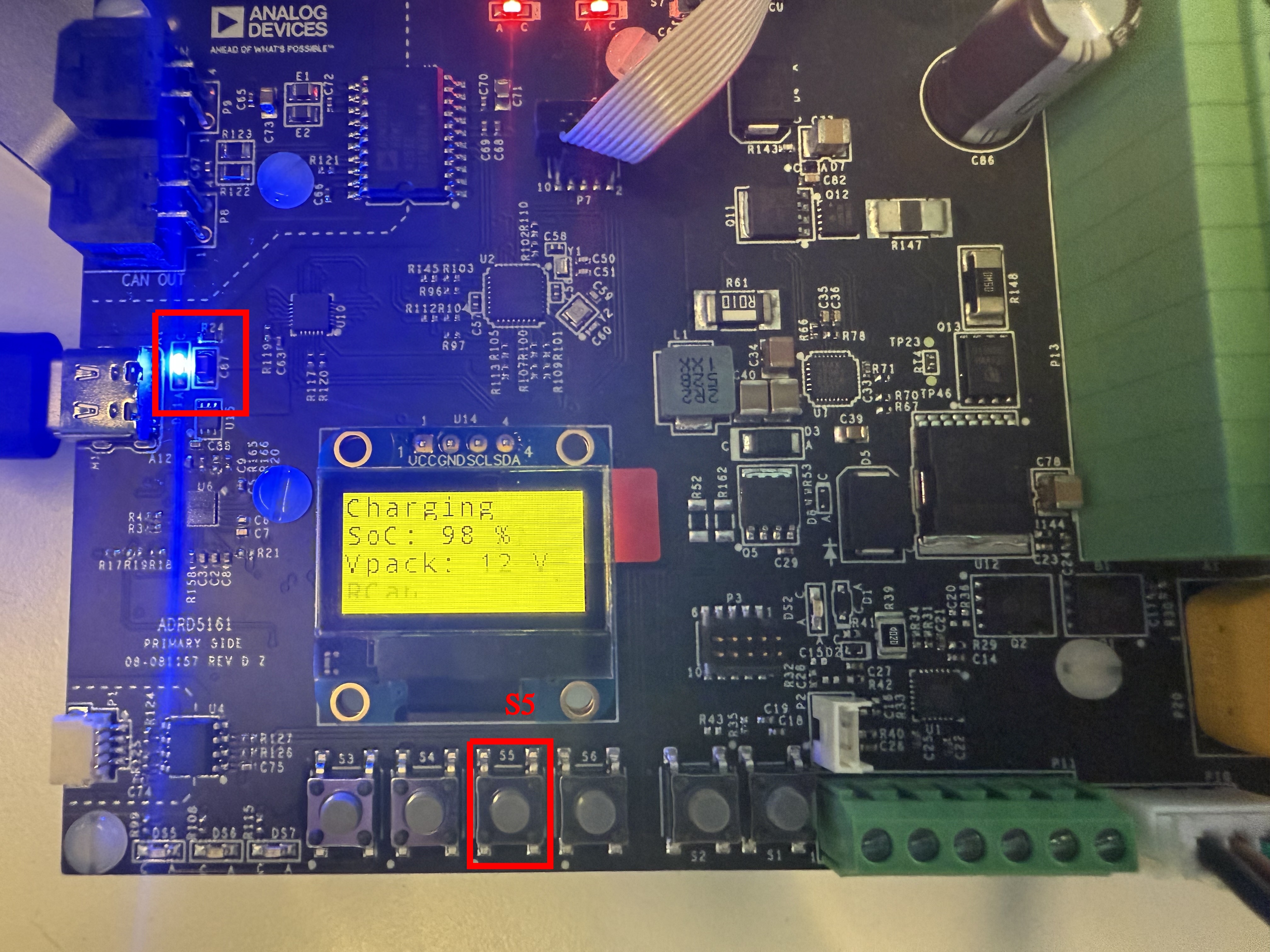
Charging State
When in the Charging State, the ADRD5161-01Z board enables the charging power path. This allows for the battery pack to be charged, without cutting the power to the additional modules. In case of an undervoltage event (e.g. connecting USB-C cable from 5V supply, instead of 20V), the module will go to Shutdown state. This state displays the following parameters, both on the screen in the serial console:
State of Charge - SoC - %
Pack Voltage - mV (serial console) & V on display
Cell1, Cell2, Cell3 Voltage - mV
Current - mA
Fuel Gauge Temperature - °C
Remaining Capacity - mAh
Full Capacity - mAh
Time to full - minutes
Temperature (from onboard Temperature sensor) - °C
To navigate OLED display, press S5. When in this state, the highlighted LED is on.
Shutdown State
When in the Shutdown state, the ADRD5161-01Z is still powered on. However, the supply to the consumers and the CAN Transceiver is cut off. This state can be triggered either by faults appearing in the powerpath, or by pressing the designated S4 button. To exit Shutdown State, the same button must be pressed.