ADRD5161-01Z Hardware Guide
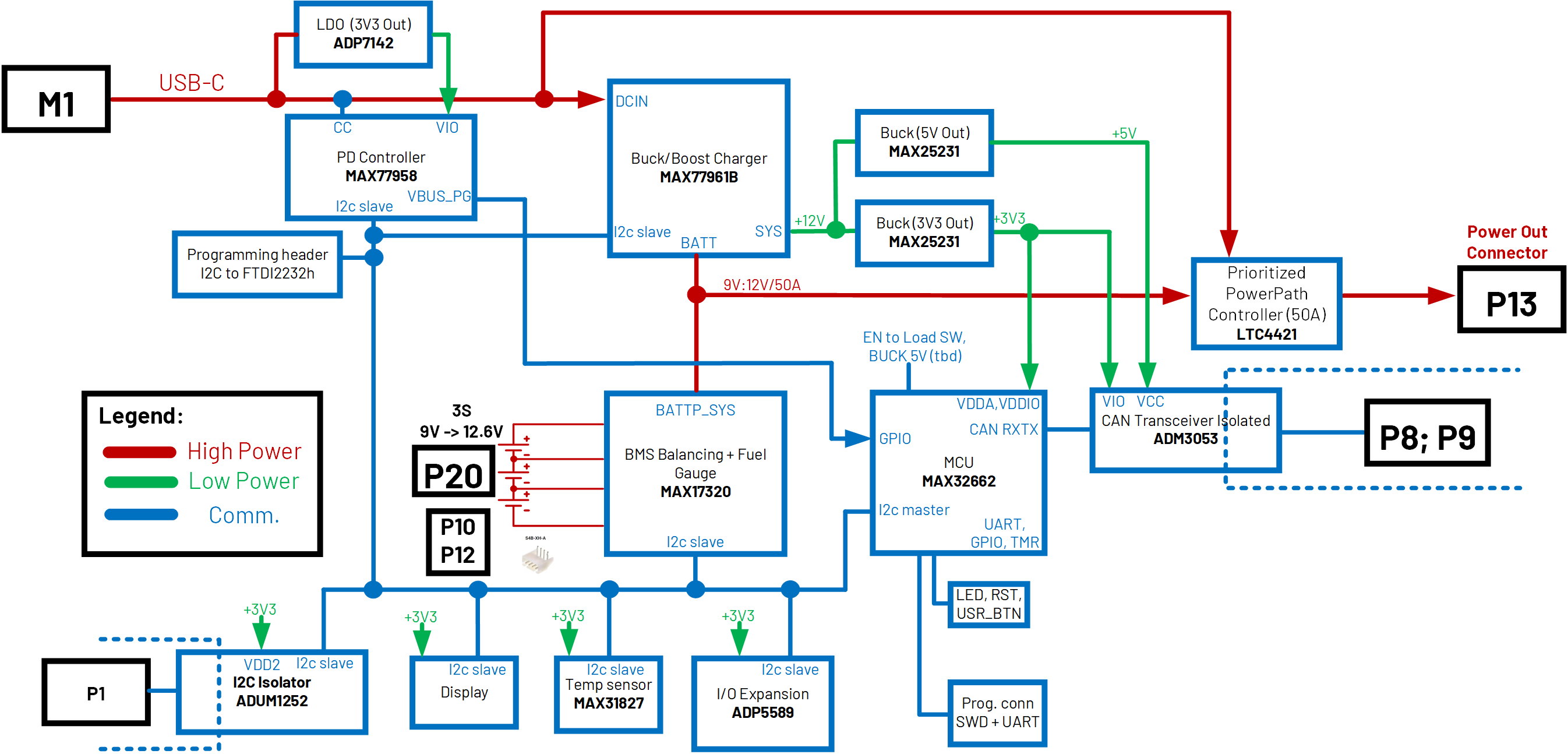
Block Diagram
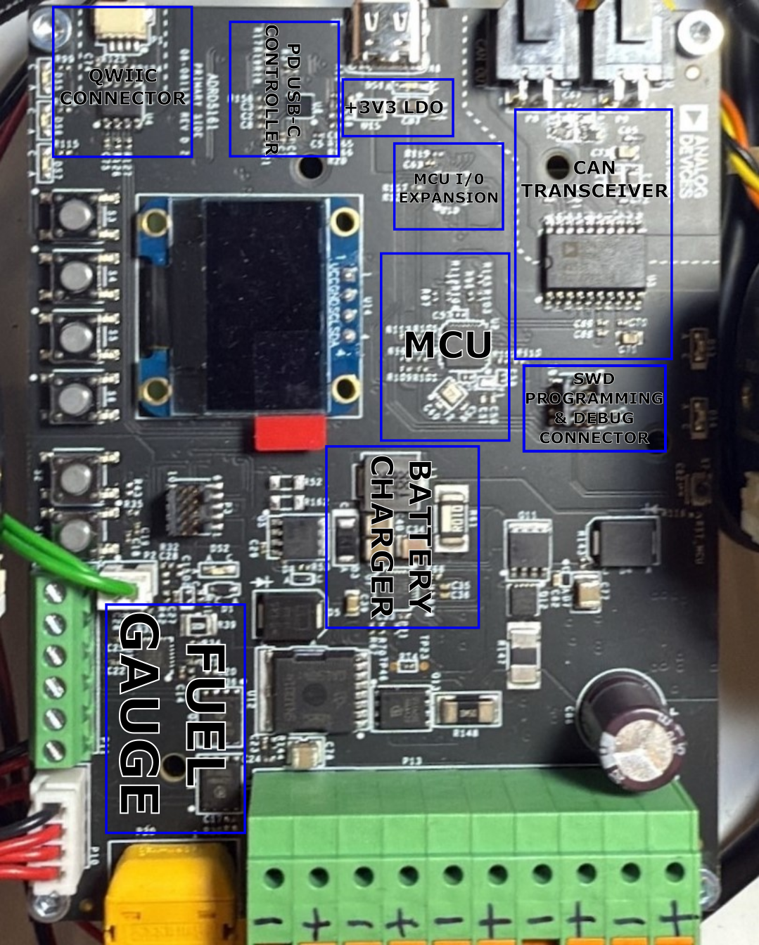
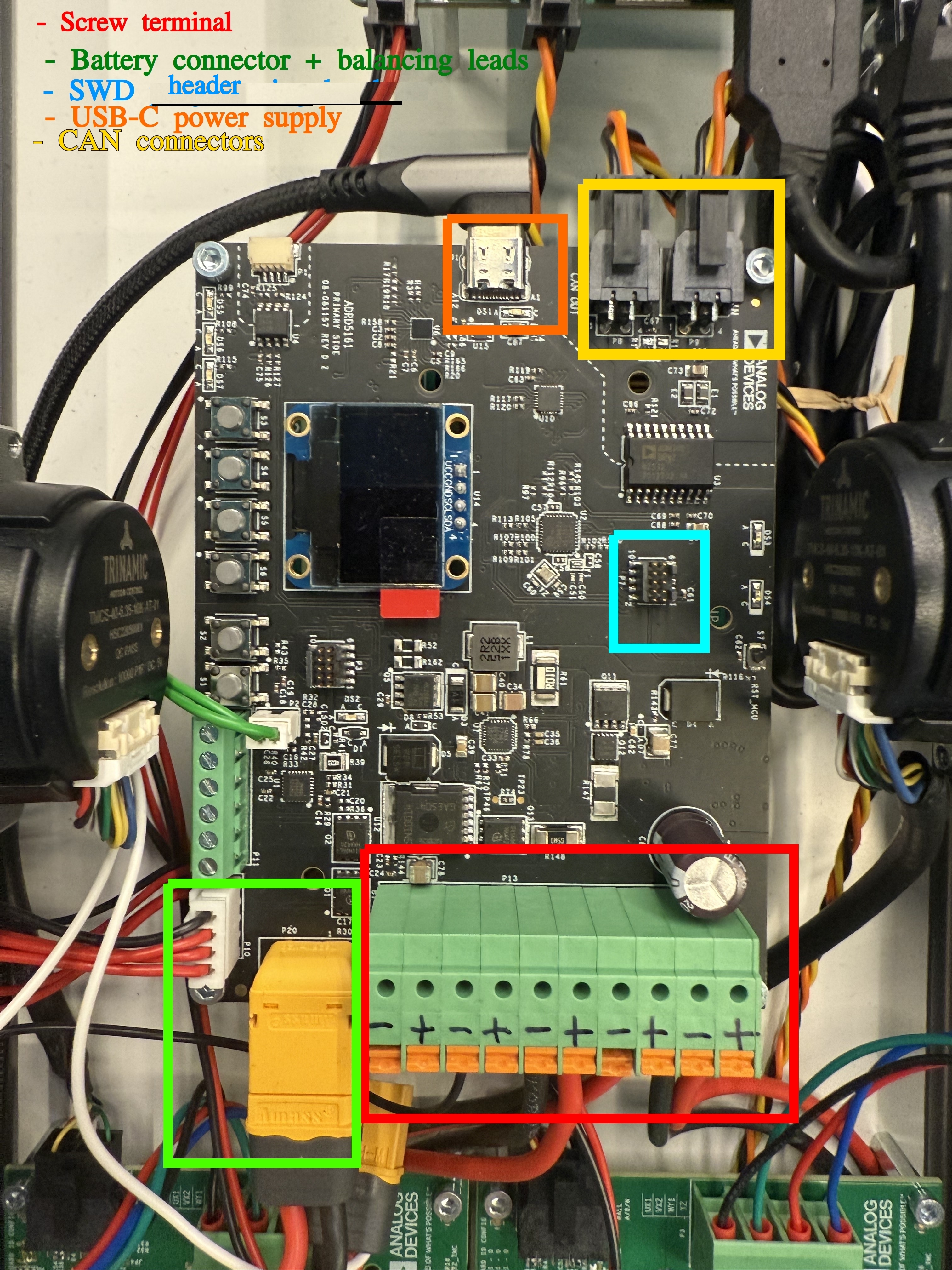
Connectors
Connections:
Battery connector: XT60 connector and corresponding cable + balancing leads
Charger connection: USB-C cable
CAN, isolated: 2x Custom header
Programming/ debugging: SWD header
Power cables to power up other modules: 10 POS terminal block
CAN cable
The ADRDx161 board family communicates via CAN bus. The two headers P8, P9 allow for daisy-chaining CAN devices.

Recommended Battery Pack
Any Li-ion or Li-polymer battery pack with 3 series cells (any number of cells in parallel). When using different battery packs, adjust the charging and discharging parameters described in the battery cell datasheet.
Recommended battery cells: Panasonic NCR18650GA (Li-ion); The default software configuration after boot is for 3 series, 2 parallel Panasonic NCR18650GA Li-ion batteries
Output Power
Maximum Output Current when USB-C adapter is not plugged in:
Maximum Continuous Discharge Current is 20A and Surge Discharge Current is 50A (for ~200us)
The Maximum Output Current is also limited by the battery pack used.
Maximum Output Current when USB-C is Plugged in:
1.7A if USB-C AC/DC Adapter supports 20V/3A PDO and Charging Constant Current is set to 3A
4.9A if USB-C AC/DC Adapter supports 20V/5A PDO and Charging Constant Current is set to 3A.
Maximum Output Voltage:
By default, the LTC4421 power path controller prioritizes the output from the USB-C AC/DC adapter. This configuration ensures that the system draws power from the adapter rather than from the battery during charging. Consequently, the maximum output voltage corresponds to the adapter’s output, typically up to 20V.
USB-C VBUS output power path can be disabled via software control.
USB-C Adapter
MAX77958 software and hardware configuration negotiates on VBUS only 20V if the USB-C AC/DC adapter can provide at least 3A minimum at 20V. To modify the configuration to negotiate other PDOs, refer to EVAL-CN0581-EBZ.
Recommended AC/DC USB-C adapter: multicomp MP009261 (supports 20V/3A).
For increased output current when the battery is charging, use an AC/DC USB-C adapter that supports 20V/5A PDO. For a 20V/5A PDO make sure that the cable used from the AC/DC adapter to the board is specified for 5A current.
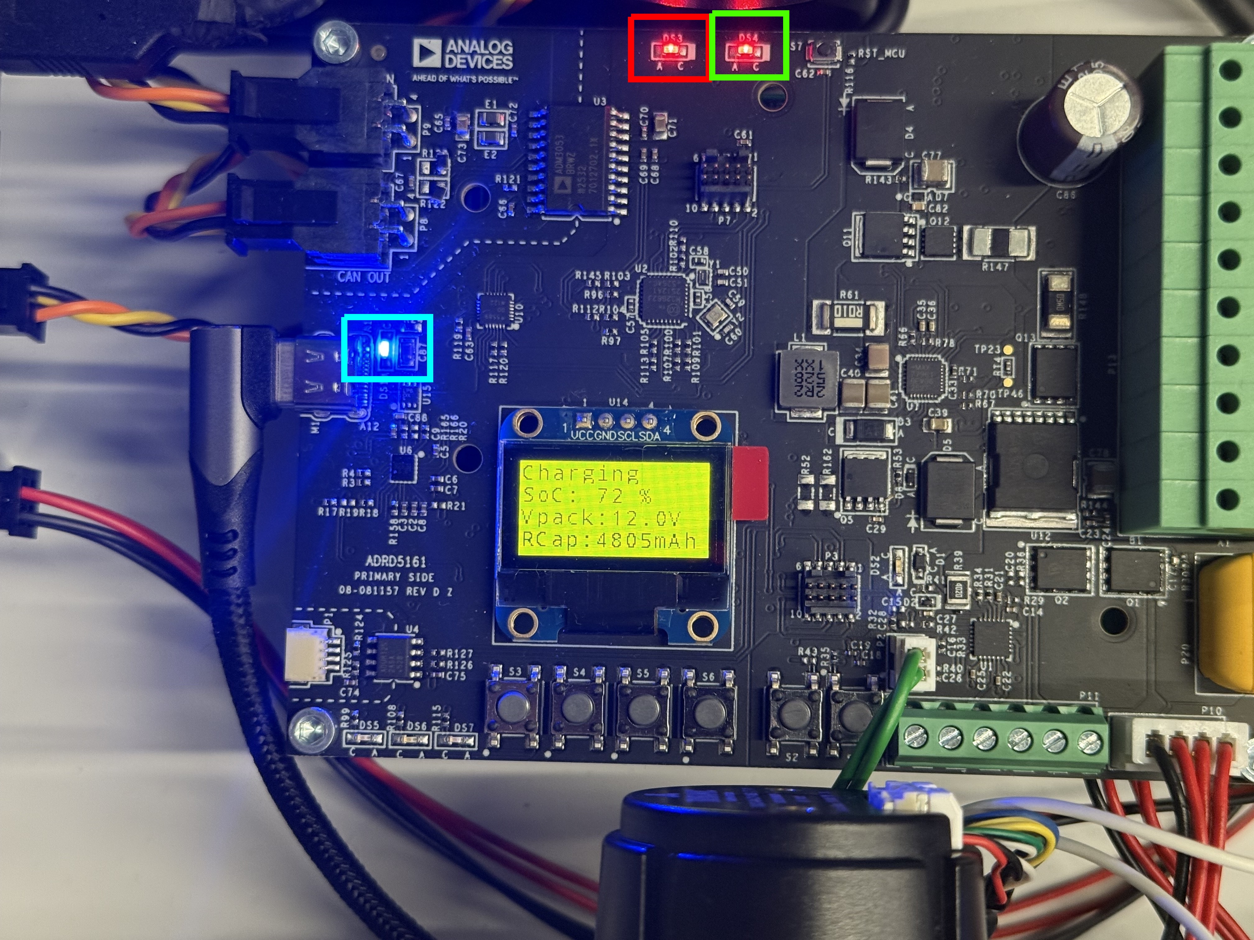
Led Indicators
When the module is connected to an external USB-C power supply, the 3 LEDs highlighted turn on. The second red LED, highlighted with green is blinking.
Design and Integration Files
A design support package consisting of the board schematic, layout, assembly and fabrication files, and more, can be downloaded from the ADRD5161-01Z page.