ADALM-LSMSPG
Active Learning Module for Low-Speed Mixed-Signal Playground
Overview
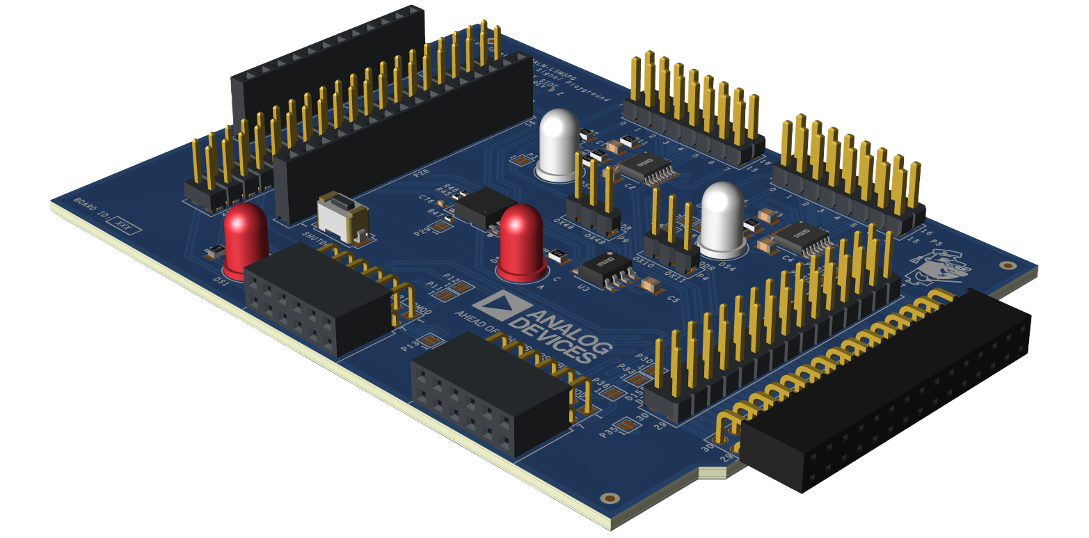
The ADALM-LSMSPG (Analog Devices Active Learning Module - Low-Speed Mixed-Signal Playground) facilitates hands-on learning of concepts related to software interfacing to hardware peripherals.
It consists of two 8-channel multifunction ADC/DAC/digital GPIOs - AD5592r and AD5593r- which have SPI and I2C interfaces, respectively.
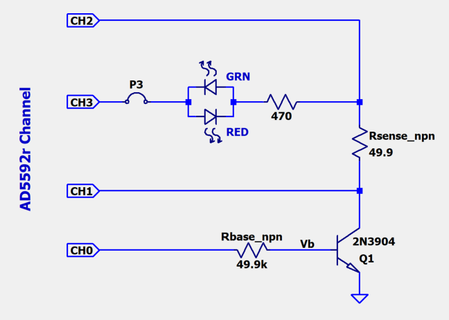
The AD5592r includes a simple NPN transistor curve tracer circuit as a representative instrumentation application.
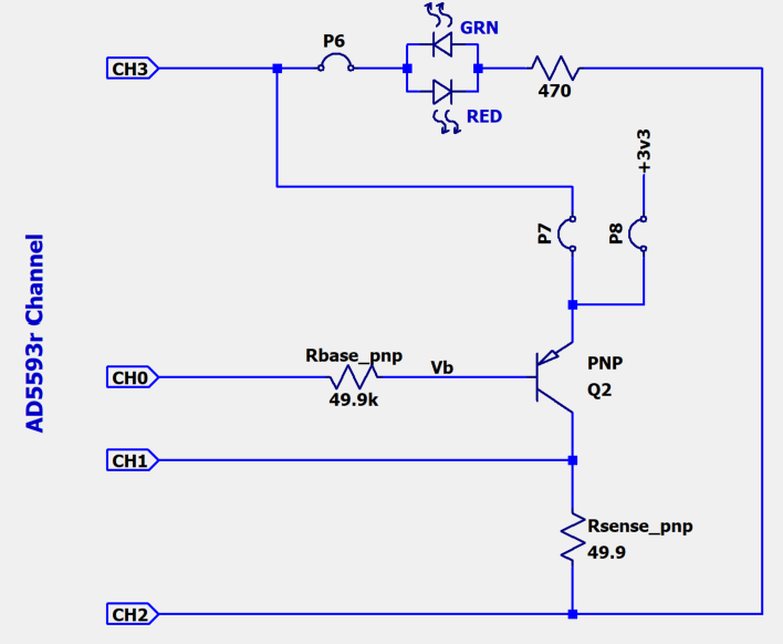
The AD5593r includes a PNP curve tracer, and both devices include bi-color LEDs for “Hello, World!” applications.
An LM75 temperature sensor is also included as a “bare minimum” peripheral example.
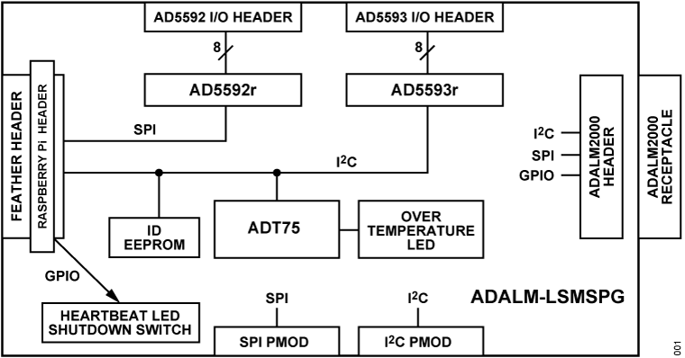
The ADALM-LSMSPG is compatible with Raspberry Pi and Feather form factor hosts, and an ADALM2000 interface allows monitoring of the SPI and I2C busses for driver development and debug.
Features
Compatible with Raspberry Pi platforms
- Compatible with Feather platforms
Other Feather platforms supporting 3.3V I/O
ADALM2000 interface for digital debug
AD5592r SPI 8-channel ADC/DAC/GPIO
AD5593r I2C 8-channel ADC/DAC/GPIO
NPN and PNP transistor curve tracer example application circuits
LM75 temperature sensor
SPI and I2C Pmod expansion headers
Applications
- Demonstrating peripheral interfacing and software for:
Embedded Linux
no-OS (Bare Metal)
Zephyr
Arduino
System Architecture
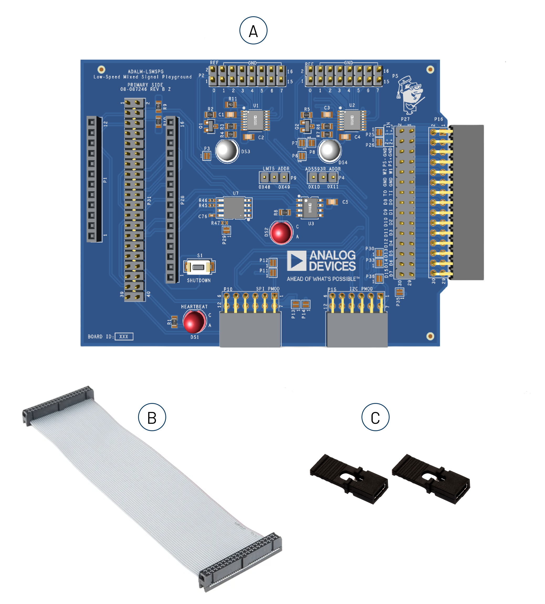
What’s Inside the Box?
Upon purchase of the ADALM-LSMSPG kit, the package comes with the following boards and accessories:
ADALM-LSMSPG main board
40-pin, 15 cm ribbon cable for Raspberry Pi
Jumpers for setting AD5592r and LM75 I2C address
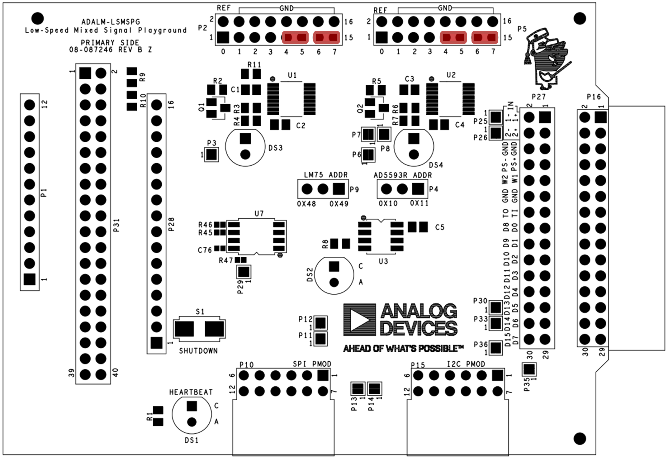
Components and Connections
ADALM-LSMSPG Pins |
Functions |
Description |
|---|---|---|
P31 |
Raspberry Pi interface |
Connect to Raspberry Pi 4, 400, 5, 500 via supplied ribbon cable. Be sure to observe polarity / pin 1 location. |
P1, P28 |
Feather interface |
Pins or stacking headers must be installed on Feather platform board, with pins facing downward. |
Note
The Raspberry Pi and Feather interfaces are mutually exclusive.
ADALM-LSMSPG Pins |
Functions |
Description |
|---|---|---|
P16 |
ADALM2000 interface |
Allows monitoring of digital traffic on the I2C, SPI, and various GPIO signals. |
P27 |
ADALM2000 through-connections |
Allows monitoring of other signals via jumper wires. |
Refer to the table below for P16, P27 signal mapping.
ADALM2000 |
ADALM-LSMSPG Signal |
|---|---|
D0 |
SPI MOSI |
D1 |
SPI MISO |
D2 |
SPI SCLK |
D3 |
SPI CE0 |
D4 |
SPI CE1 |
D5 |
I2C SDA |
D6 |
I2C SCL |
D7 |
AD5592r IO3 |
D13 |
GPIO19 |
D14 |
GPIO25 |
D15 |
AD5593r IO3 |
ADALM-LSMSPG Pins |
Functions |
Description |
|---|---|---|
P31 |
AD5592r Connections |
Analog I/O (ADC/DAC), digital GPIO |
P5 |
AD5593r Connections |
Analog I/O (ADC/DAC), digital GPIO |
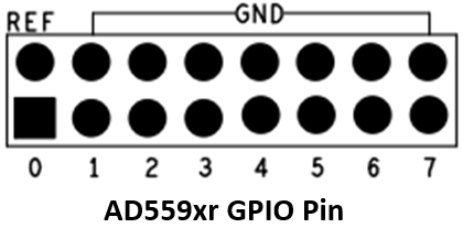
Refer to the figure below for P2, P5 signal mapping.
Address Selection Jumpers
System Monitor/Control
DS1: Heartbeat LED
S1 : Raspberry Pi Shutdown (set in config.txt), Feather reset
Curve Tracer Application Circuits
The AD5592r and AD5593r drive simple NPN and PNP (respectively) curve tracer circuits. This represents a simple DC test instrument that involves the “set a current, set a voltage, take a measurement, do some math, step, repeat” sequence of operations. The details of the experiments are covered in the Tools for LSMSPG Lesson.
The PNP curve tracer has two options for the emitter drive: AD5593r CH3 (default), or the 3.3V supply rail.
Hardware Setup
Raspberry Pi Setup:
For Raspberry Pi Zero 2 W, 4, and 5, use the included ribbon cable to make the connection as shown in the figure below.
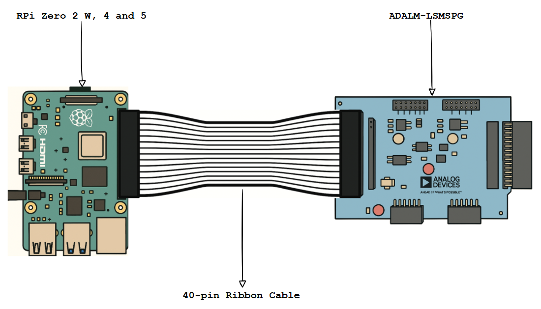
Figure 8 RPi Zero 2W/4/5 and ADALM-LSMSPG with 40-pin Ribbon Cable Connection
For Raspberry Pi 400 and 500, use the included ribbon cable to make the connection as shown in the figure below.
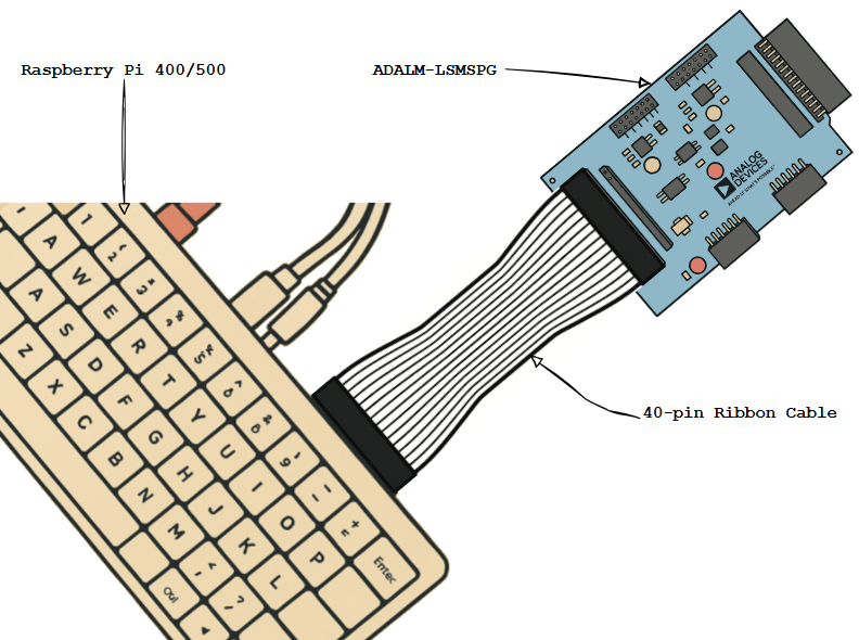
Figure 9 RPi 400/500 and ADALM-LSMSPG with 40-pin Ribbon Cable Connection
Feather Setup:
Most Feather platform boards ship without peripheral headers installed. Refer to the board’s instructions, and install either:
Downward-facing 100-mil post headers
Stacking headers with posts extending from the reverse side of the board.
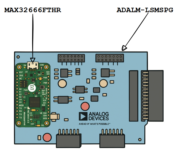
Install the Feather on P20 as shown in the Figure below.
Software Setup
Raspberry Pi Setup
Prepare an SD card with ADI Kuiper Linux following the instructions at ADI Kuiper Linux Guide.
Add the following to the end of /boot/config.txt:
# config.txt additions

dtoverlay=rpi-adalm-lsmspg

# Heartbeat blinky:
dtparam=act_led_gpio=20
dtparam=act_led_trigger=heartbeat
dtparam=i2c_arm=on

# Short GPIO21 (pin 40) to ground for shutdown:
dtoverlay=gpio-shutdown,gpio_pin=21,active_low=1,gpiopull=up
With the ADALM-LSMSPG connected, the heartbeat LED will begin beating on boot. The shutdown button is a convenient means of shutting down the Raspberry Pi properly in headless situations (no local monitor or keyboard). Press the shutdown button, wait 5 seconds after the heartbeat LED stops blinking, and then it is safe to remove power.
MAX32666FTHR Setup
The MAX32666FTHR includes a MAX32625PICO debugger that can be used to load the ADALM-LSMSPG firmware image. Prepare the MAX32625PICO itself with the MAX32666FTHR-specific DAPLink image from: MAX32625PICO firmware images
Leave the MAX32625PICO plugged in, and plug in the MAX32666FTHR using another
USB-Micro cable. Connect the debug interface to the MAX32666FTHR with the supplied
10-pin ribbon cable. Download the ADALM-LSMSPG tinyiiod firmware image
(filename adalm-lsmspg.zip) from:
ADALM-LSMSPG firmware (no-OS releases)
Unzip the archive, copy the adalm-lsmspg_maxim_iio.hex file, and paste it into
the DAPLINK mass storage device (typically D: or E: on Windows systems).
The DAPLINK drive will auto-eject, and the heartbeat LED on the ADALM-LSMSPG
will begin blinking.
Application Setup
Detailed instructions for various application software examples are included in the
Tools for LSMSPG Lesson,
as well as other supporting material. The underlying API for Raspberry Pi/Linux and
bare-metal tinyiiod servers is libiio, which can be installed from:
Libiio
Once installed, information about the ADALM-LSMSPG context can be displayed by
running iio_info and passing the URI argument.
For Kuiper Linux, the default hostname is analog. Example:
iio_info -u ip:analog.local
For the MAX32666FTHR running the tinyiiod firmware, run:
iio_info -u serial:COM4
Replace COM4 with the appropriate COM port number on Windows, or /dev/ttyX on Linux.
The Tools for LSMSPG Lesson tutorial contains many additional examples of communicating with the ADALM-LSMSPG.
Additional Resources
Design & Integration Files
Download
ADALM-LSMSPG Design & Integration Files
Schematic
PCB Layout
Bill of Materials
Allegro Project
Help and Support
For questions and more information, please visit the EngineerZone Support Community or contact your local ADI representative.