All the products described on this page include ESD (electrostatic discharge) sensitive devices. Electrostatic charges as high as 4000V readily accumulate on the human body or test equipment and can discharge without detection.
Although the boards feature ESD protection circuitry, permanent damage may occur on devices subjected to high-energy electrostatic discharges. Therefore, proper ESD precautions are recommended to avoid performance degradation or loss of functionality. This includes removing static charge on external equipment, cables, or antennas before connecting to the device.
Using Linux as software
Necessary files
The following files are needed for the system to boot:
HDL boot image: system_top.bit
Linux simple image: simpleImage.strip
Programming script: run.tcl
Instructions on how to choose the boot files from the SD card can be found in
the Platform-Specific Manual Steps section from here:
Hardware Configuration.
Instructions on how to manually build the boot files from source can be found
here:
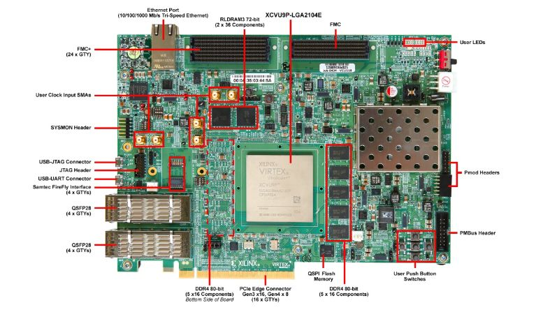
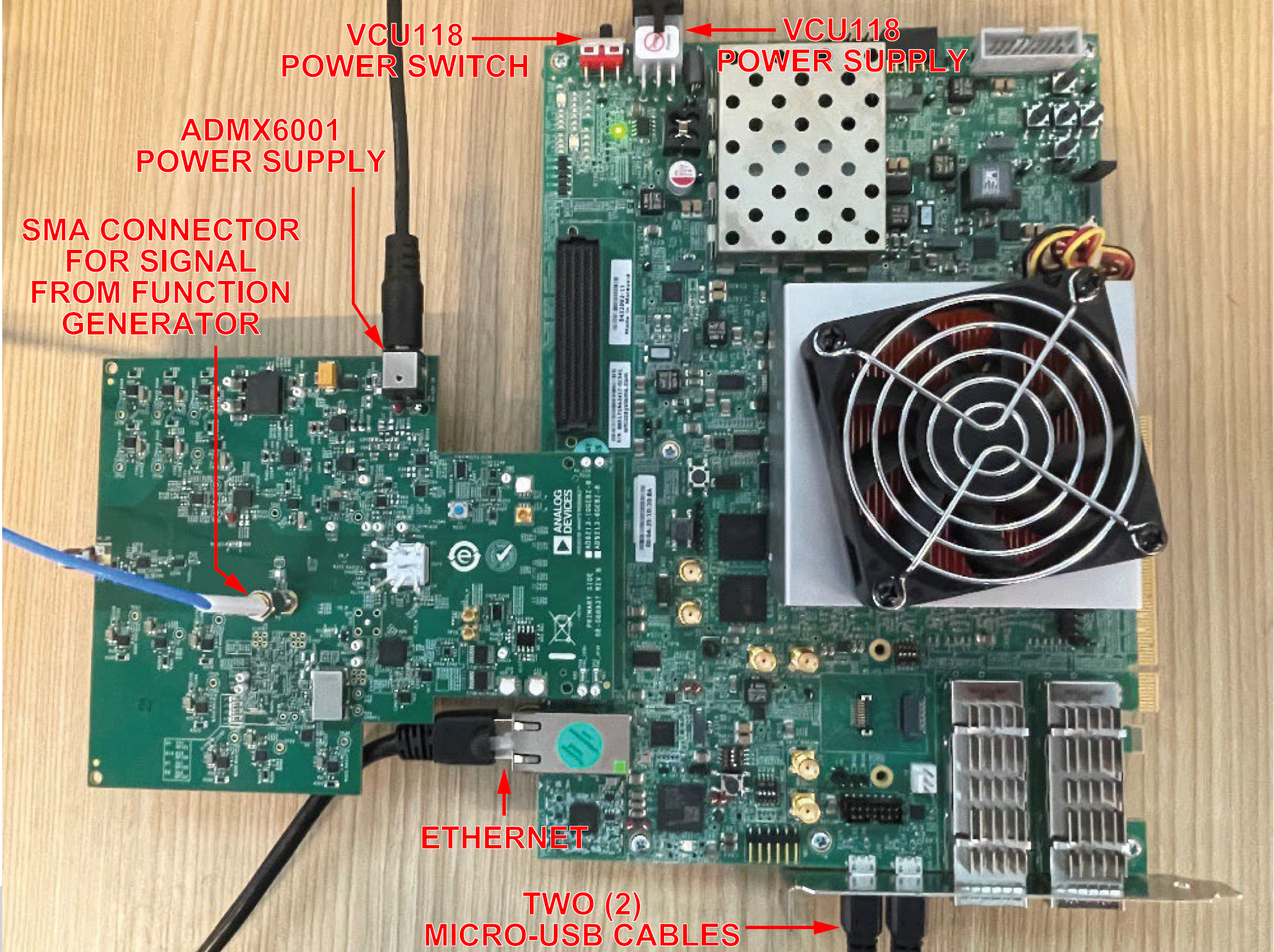
Connect the Ethernet cable from your router/switch to the Ethernet port on
the VCU118.
Connect both Micro-USB cables to the UART ports on the VCU118.
Connect the power supply to the ADMX6001-EBZ and power it on first.
Connect the power supply to the VCU118 and power it on second.
Warning
Always power the ADMX6001-EBZ before the VCU118. Power down in reverse
order.
Configuring the host PC network
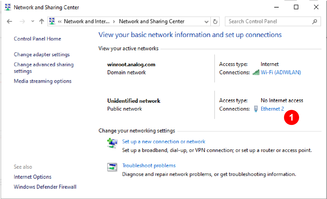
Follow these steps to configure the Ethernet IP address:
Control Panel -> Network and Sharing Center -> click Ethernet to open the
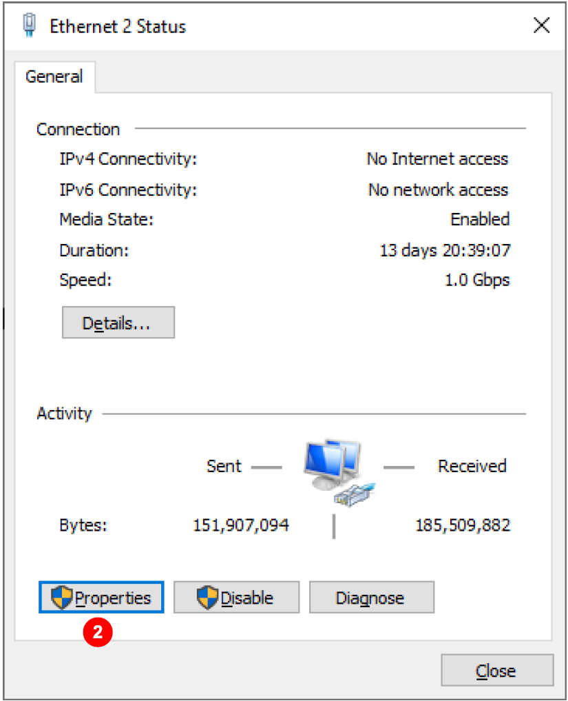
Ethernet Status window, as shown in figure below.
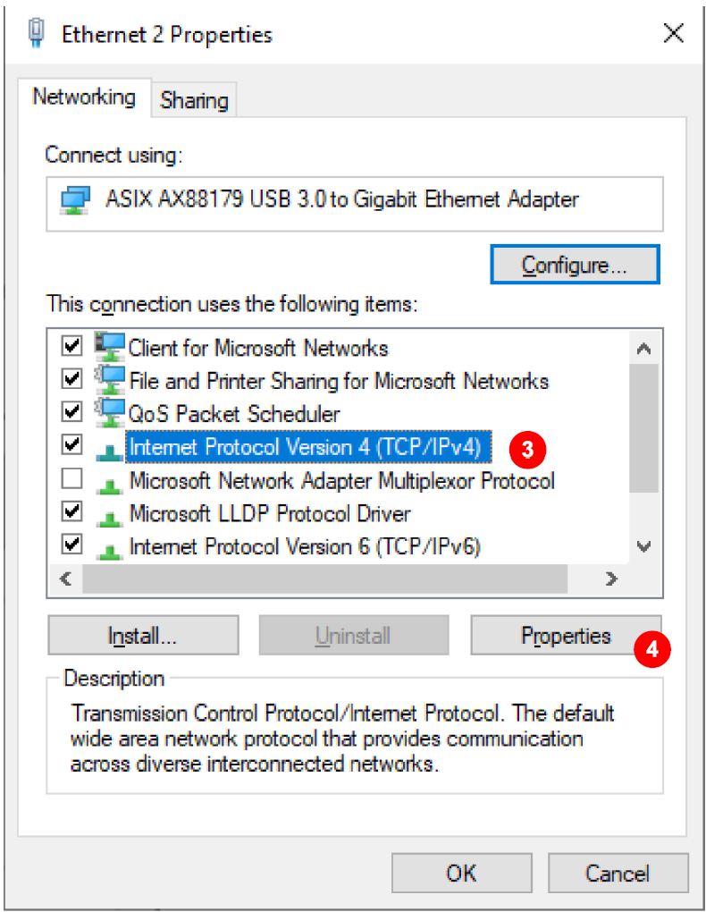
Click Properties to open the Ethernet Properties window.
Select Internet Protocol Version 4 (TCP/IP) and then click Properties to open
the Internet Protocol Version 4 (TCP/IPv4) Properties window.
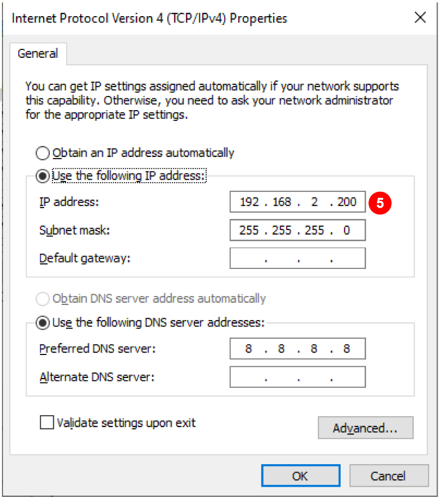
Review/change IP address.
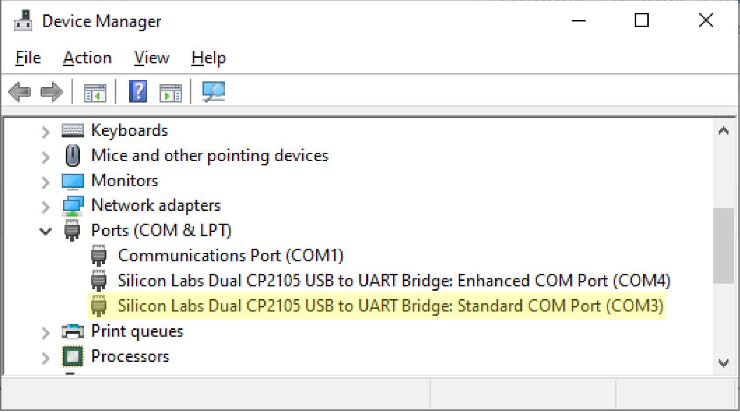
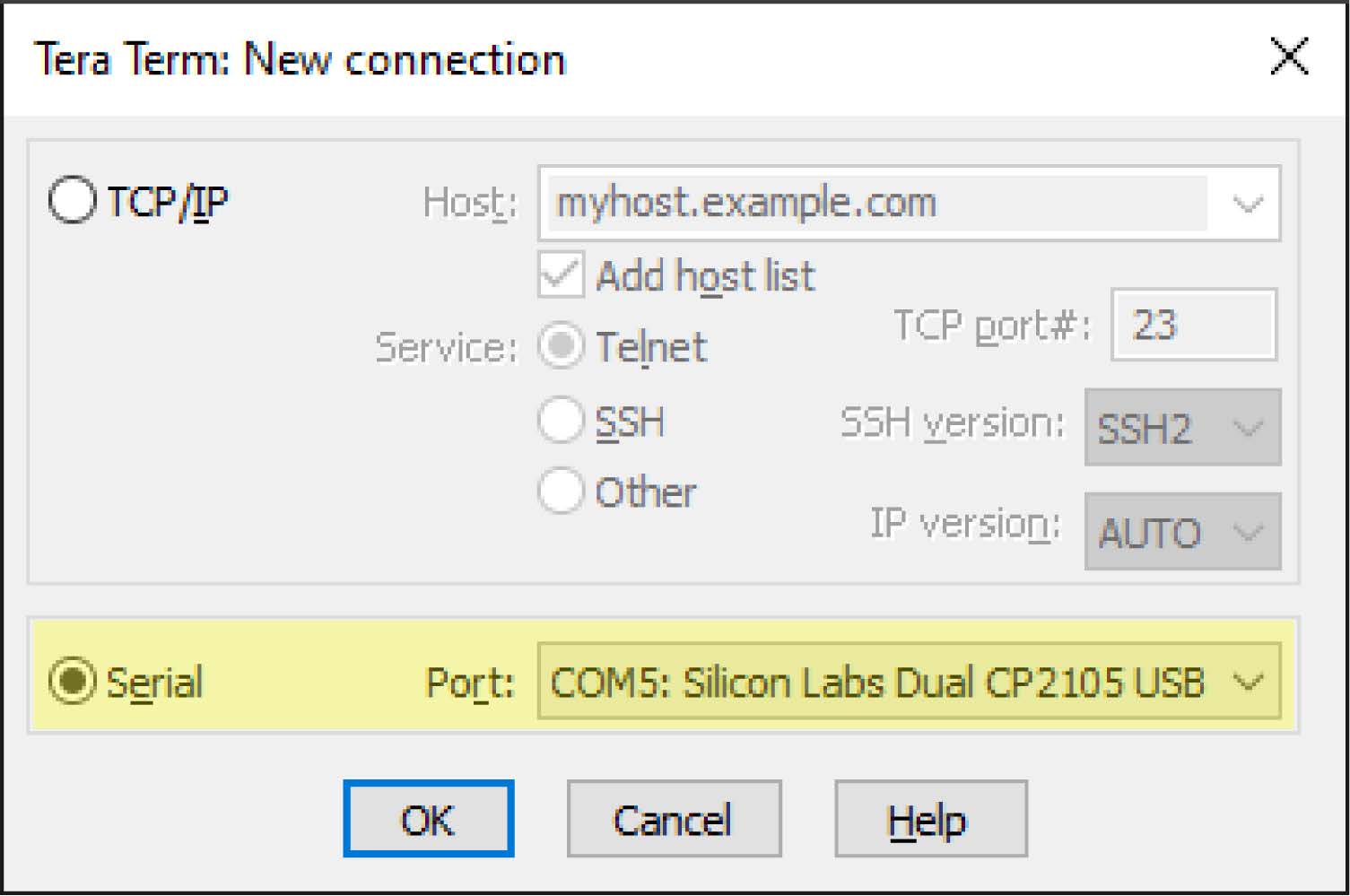
Find the UART COM port of the Xilinx VCU118 board by opening Device Manager
and expanding Ports (COM & LPT). Locate Silicon Labs Dual CP2105 USB to UART
Bridge Standard COM Port (COMx) to get the COM port number for the Tera Term
serial terminal connection. The user may need to update the CP210x USB to
UART Bridge VCP drivers.
FPGA programming
The programming files for Xilinx VCU118 FPGA are provided as a .zip file. Unzip
the files to a working folder for all of the required files.Refer to the
Hardware Setup section. The 12V power adapters to both the ADMX6001-EBZ board
and the Xilinx VCU118 FPGA board must be unplugged from the wall outlets before
turning on the boards.
Turn on the boards sequentially. First, make sure that the connection of the 12V
power adapter output to the barrel connector (P4) on the ADMX6001-EBZ board is
securely in place, then turn on the ADMX6001-EBZ board by plugging in the 12V
power supply to the wall outlet. The DS10 and DS11 on the same edge as the
barrel connector on the ADMX6001-EBZ board must be lit. Otherwise, unplug the
12V power adapter from the wall outlet and wait for about 10 seconds before
plugging the 12V power supply back to the wall outlet. Second, make sure that
the power switch on the Xilinx VCU118 board is in the OFF position and the
output of the 12V power supply is securely in place. Plug in the 12V power
adapter for the Xilinx VCU118 board to the wall outlet, then turn on the Xilinx
board by turning the power switch to the ON position.
Before programming the Xilinx VCU118 board, it is important to configure
Ethernet to an IP 192.168.2.xx where xx can be any number between 2 and 255. If
a USB adapter with Ethernet port is used, plug in the USB adapter before
reviewing and/or configuring the IP address. Install the Silicon Labs VCP
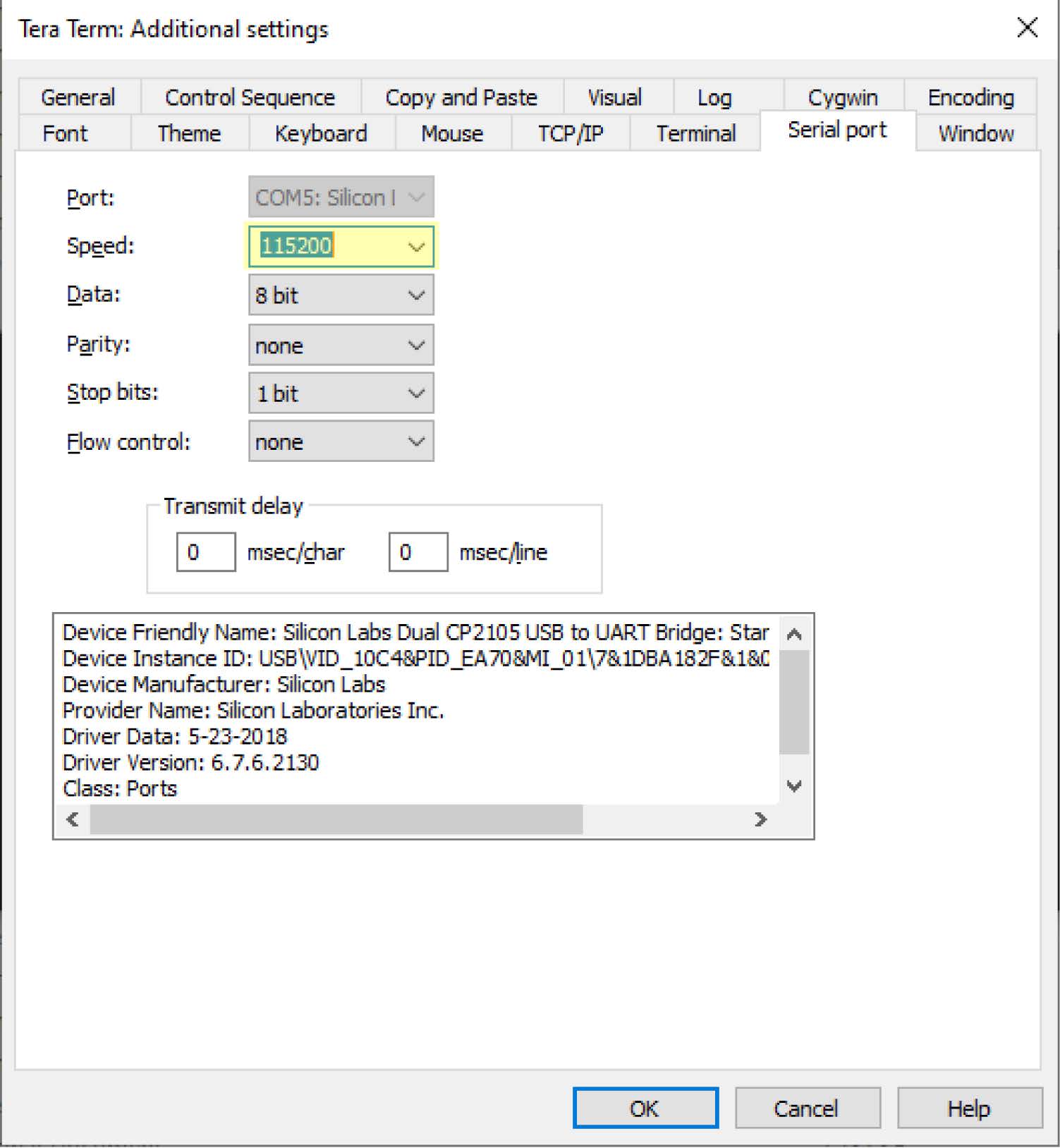
drivers and verify the UART COM port appears in Windows Device Manager. Open
Tera Term and connect to the detected COM port at 115200 baud, 8N1 to
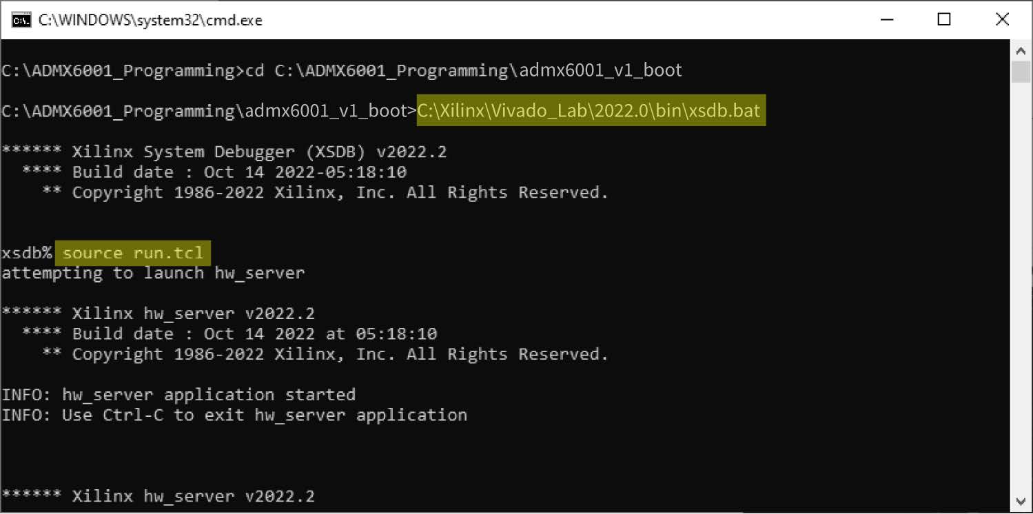
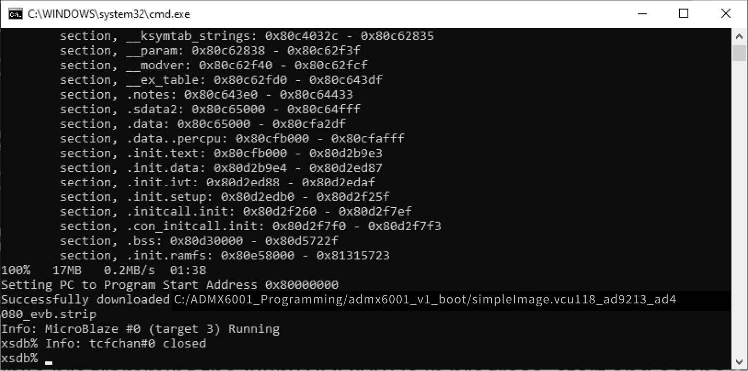
monitor the boot process. Launch an xsdb shell from Vivado Lab Edition:
xsdb
Program the VCU118 FPGA board:
xsdb%sourcerun.tcl
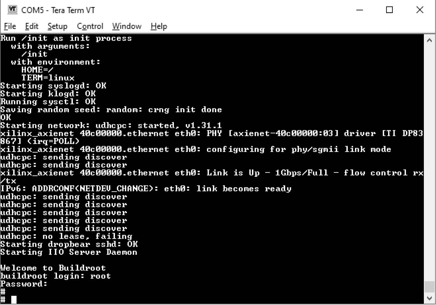
While programming the Xilinx VCU118 is in progress, open and start the serial
terminal Tera Term session to observe the boot process and log in to the
Xilinx VCU118. Start and connect the serial terminal Tera Term session using the
COM port found previously. In Tera Term, click Setup -> Serial port … to set the
speed to 115200. Continue monitoring the Xilinx VCU118 boot process. Once the
process is complete, log in with the following information:
Login: root Password: analog
Note the following:
For the Xilinx Vivado Lab version, only xsdb.bat is available
(C:XilinxVivado_Lab2024binxsdb.bat).
It is required to program the Xilinx VCU118 board twice in the Vivado Lab
window. Run source run.tcl and wait for the login message to appear in the Tera
Term window. Run source run.tcl a second time. Observe the boot process in the
Tera Term window and log in. If using Python scripts is preferred, skip the
Configure and Control the ADMX6001-EBZ With IIO Oscilloscope section and the
ADMX6001-EBZ Data Acquisition With IIO Oscilloscope section, and go directly to
the Configure and Control ADMX6001-EBZ With Python Scripts section.
Console output
The following is what is printed in the serial console, after you have connected
to the proper ttyUSB or COM port:
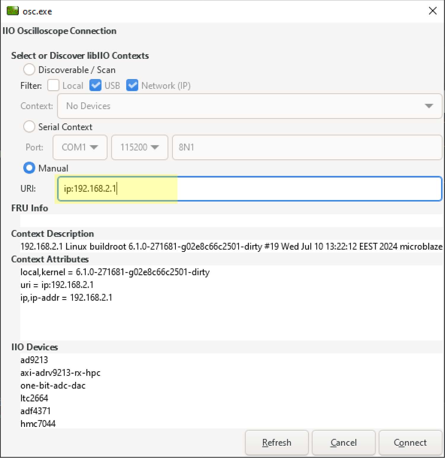
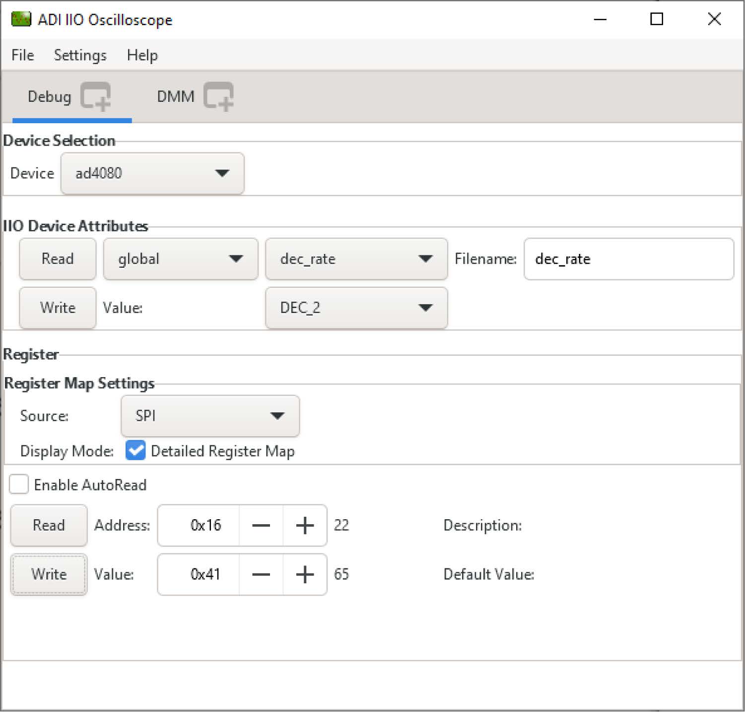
Launch the IIO-Oscilloscope application and go to**Settings → Connect**. In
the popup window, connect to Xilinx VCU118 with manual URI ip. Once the IIO
device is connected, the user can read/write registers and view the plot of
captured data
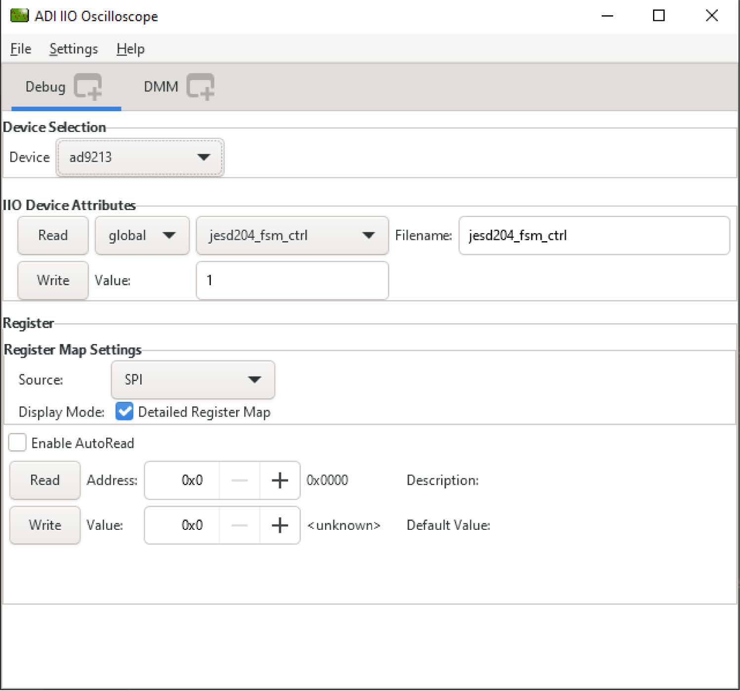
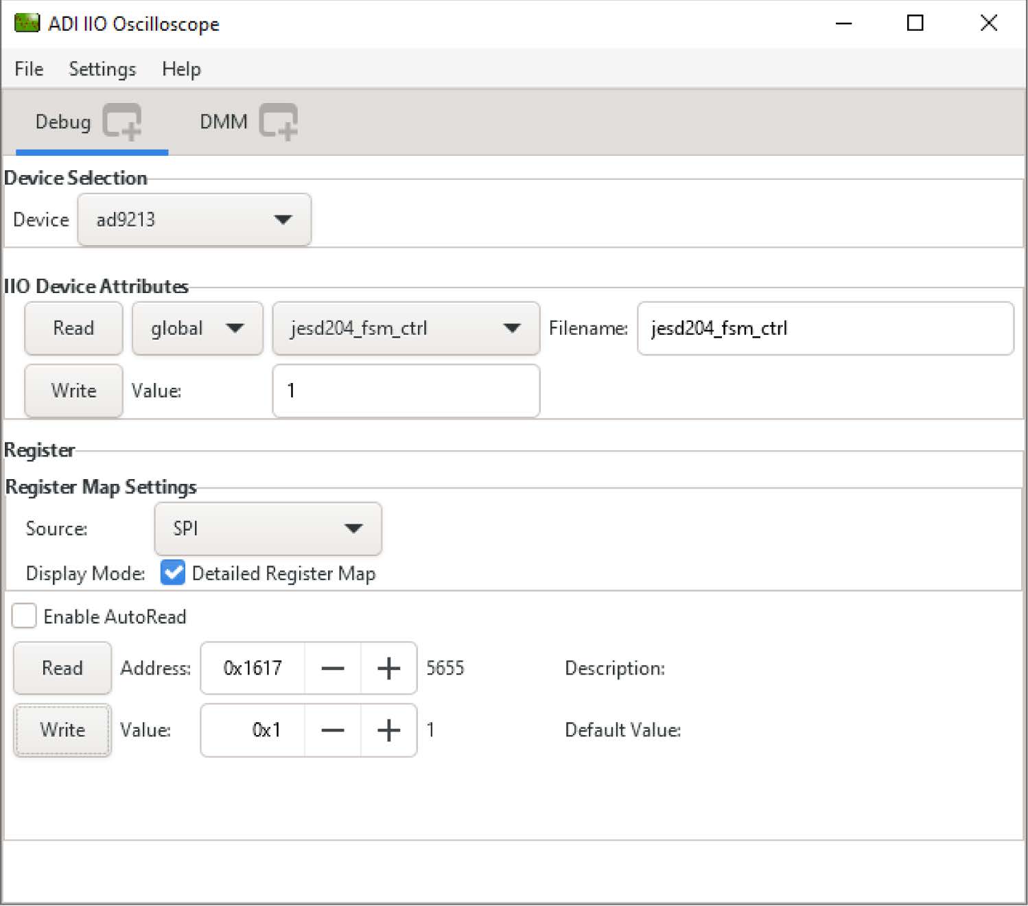
Configure the AD9213 high-speed path
Set the following registers for the AD9213 high-speed path:
Register
Value
0x1617
0x01
0x1601
0x01
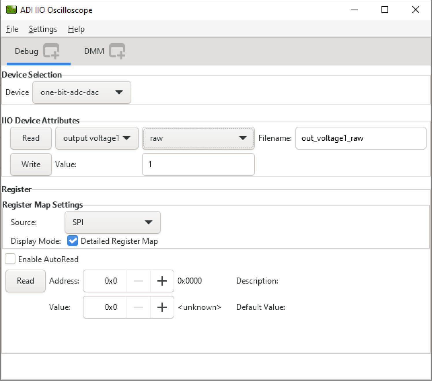
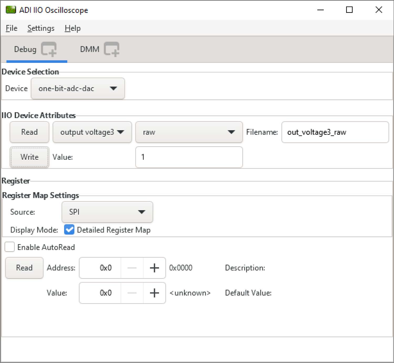
ltc2664_clr
1
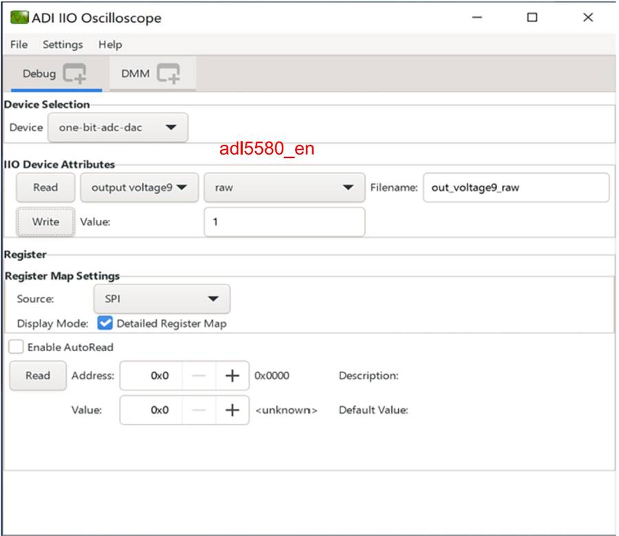
adl5580_en
1
The AD9213 high-speed path is ready for capturing data.
Configure the AD4080 precision path
Before capturing the AD4080 precision path data with the IIO Oscilloscope, a few
registers need to be set.
The AD4080 low voltage differential signaling (LVDS) data interface is highly
configurable. In the ADMX6001-EBZ design, the AD4080 is configured to output the
result data on single data lane. The AD4080 data interface configuration
Register 0x15 and Register 0x16 need to be configured so that the Xilinx VCU118
controls are aligned with AD4080 conversion data for correct data output.
Complete the following steps for setting the AD4080 data interface configuration
registers:
AD4080 Register 0x15 set to 0x50 to enable the fixed pattern test, as shown in
Figure 26. This step sets AD4080 in test mode.
In test mode, the 20-bit AD4080 data is expected to be binary 1010 1100 0101
1101 0110, decimal −342570, or hexadecimal 0xAC5D6. Save the AD4080 data to a
.csv file in IIO Oscilloscope and check the value. Refer to the ADMX6001-EBZ
Data Acquisition With IIO Oscilloscope section for saving data in IIO
Oscilloscope.
If the AD4080 data is different from the expected decimal −342570, set the
AD4080 Register 0x15 to one of the following values: 0x51, 0x61, 0x71, 0x81,
0x91, 0x01, 0x11, 0x21, 0x31, or 0x41, as shown in Figure 27. Save the data to a
.csv file and check the value. Repeat this step with a value in the list until
the AD4080 data is exactly −342570. The AD4080 register setting is completed.
Set AD4080 Register 0x15 back to 0x40 to disable the fixed pattern test and
enable AD4080 normal mode.
The AD4080 data interface configuration registers are set and the AD4080 is
ready for data acquisition.
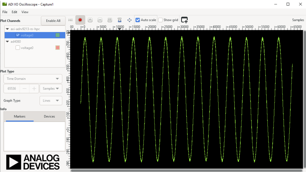
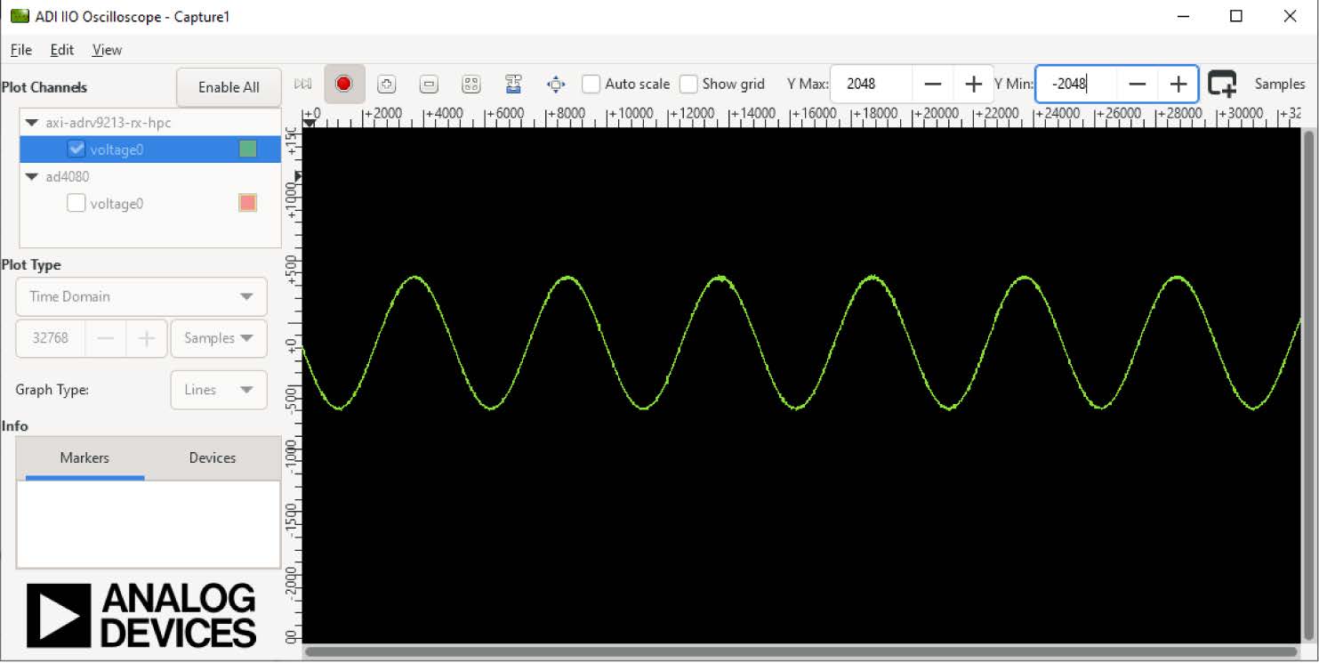
IIO-OSCILLOSCOPE plot window
Data captured by the the AD9213 high-speed path and the AD4080 precision path
can be visualized and saved to a .csv file in the IIO Oscilloscope plot window.
Captured Signal Time Domain for adrv9213
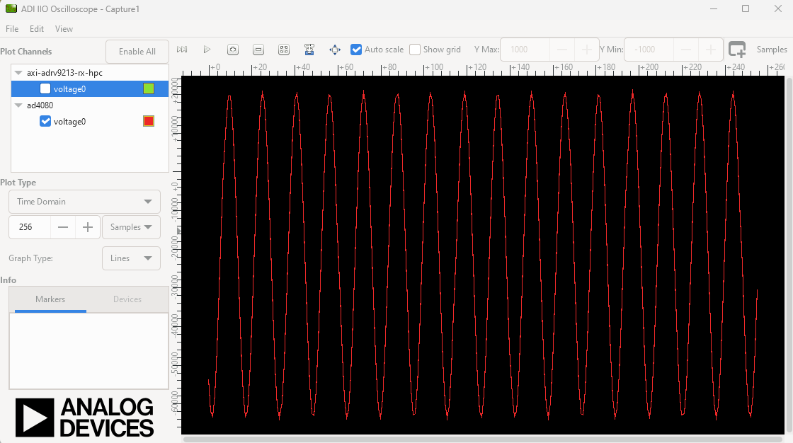
Captured Signal Time Domain for ad4080
The two data paths are listed in the top-left corner. Check one or both and then
click the Capture/Stop button to view the data stream. For the IIO Oscilloscope
to work smoothly, it is recommended that the number of samples is set to power
of 2, such as 210 (1024) or 216 (65536). The IIO Oscilloscope supports only one
scale for each axis so that it is not practical to view the AD9213 high-speed
path and the AD4080 precision path simultaneously because the AD9213 (10GSPS)
high-speed path is 320 times faster than the AD4080 (31.25MSPS) precision path
for the horizontal axis and AD4080 (20-bit) has higher bit resolution than
AD9213 (12-bit) for the vertical axis in the ADMX6001-EBZ design.
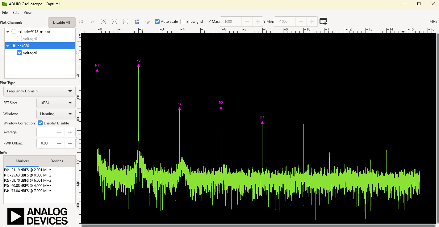
The IIO Oscilloscope plot window can also view the captured data in the
frequency domain.
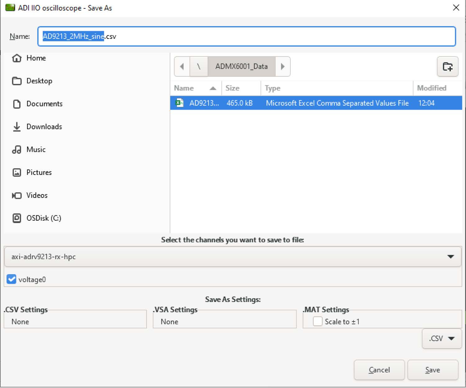
The data can be saved in a .csv file for post processing and analysis. From the
File menu, select Save As to open the Save As window. Make sure to select the
path from the dropdown list and select the correct checkbox before clicking the
Save button on bottom-right.
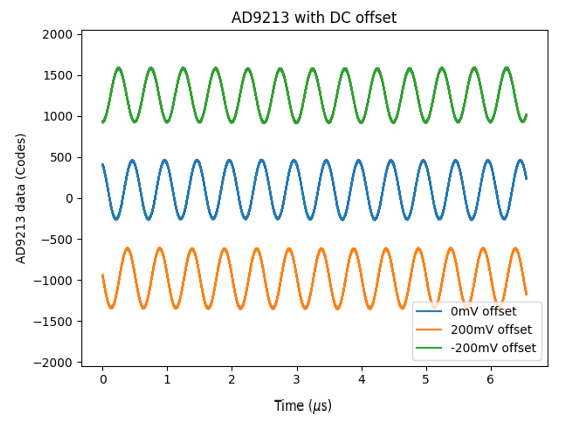
Input signal offset shift for AD9213
The input signal is often from transducers or sensors as a unipolar signal with
DC offset, whereas the AD9213 works best with differential input. By biasing the
ADL5580 input terminal with the output of the precision DAC LTC2664, the ADL5580
converts the unipolar signal to a differential signal with an adjustable DC
offset to maximize the utility of the AD9213 input dynamic range. The actual use
case may vary depending on the specific application.
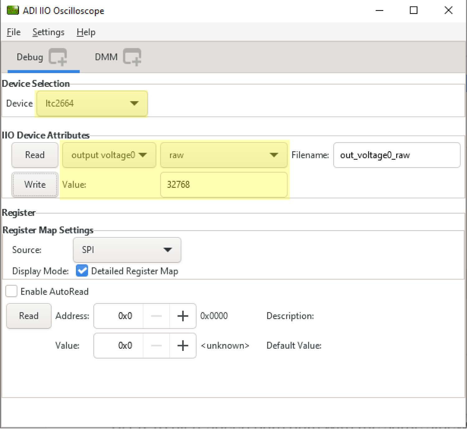
The DAC value of 32768 corresponds to 0V and is used as the default biasing to
ADL5580. To achieve a targeted DC offset shift x mV, the DAC value can be
calculated as
DAC value = 32768×(1 + x /5000)
where x is the DC offset in mV.
Round the DAC value to the nearest integer as the DAC LTC2664 input. The DAC
output range is −5V to +5V.
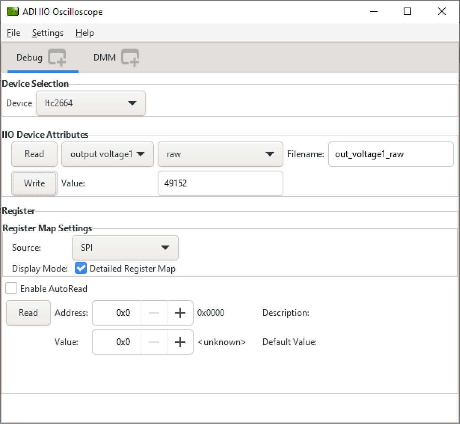
To change the LTC2664 DAC value for ADL5580 biasing, write the DAC value as raw
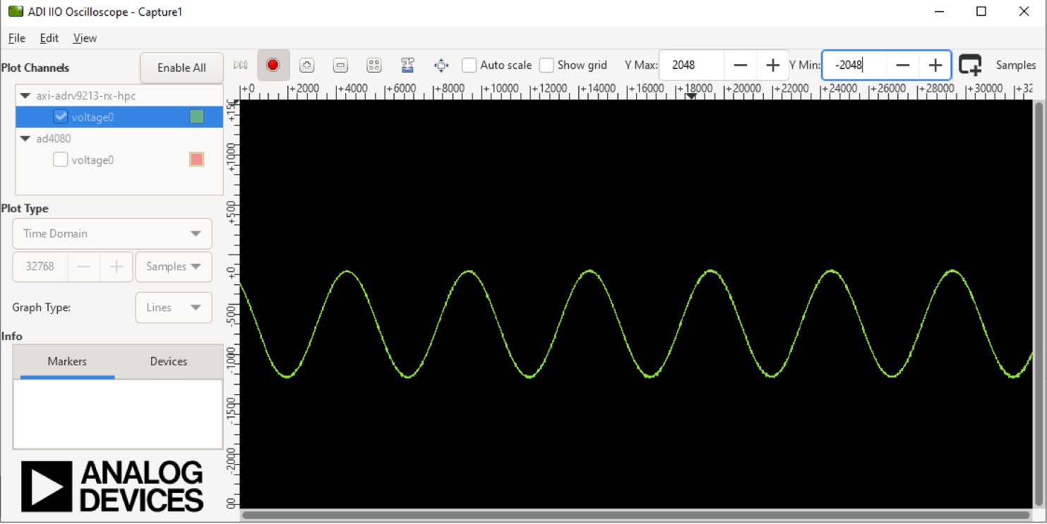
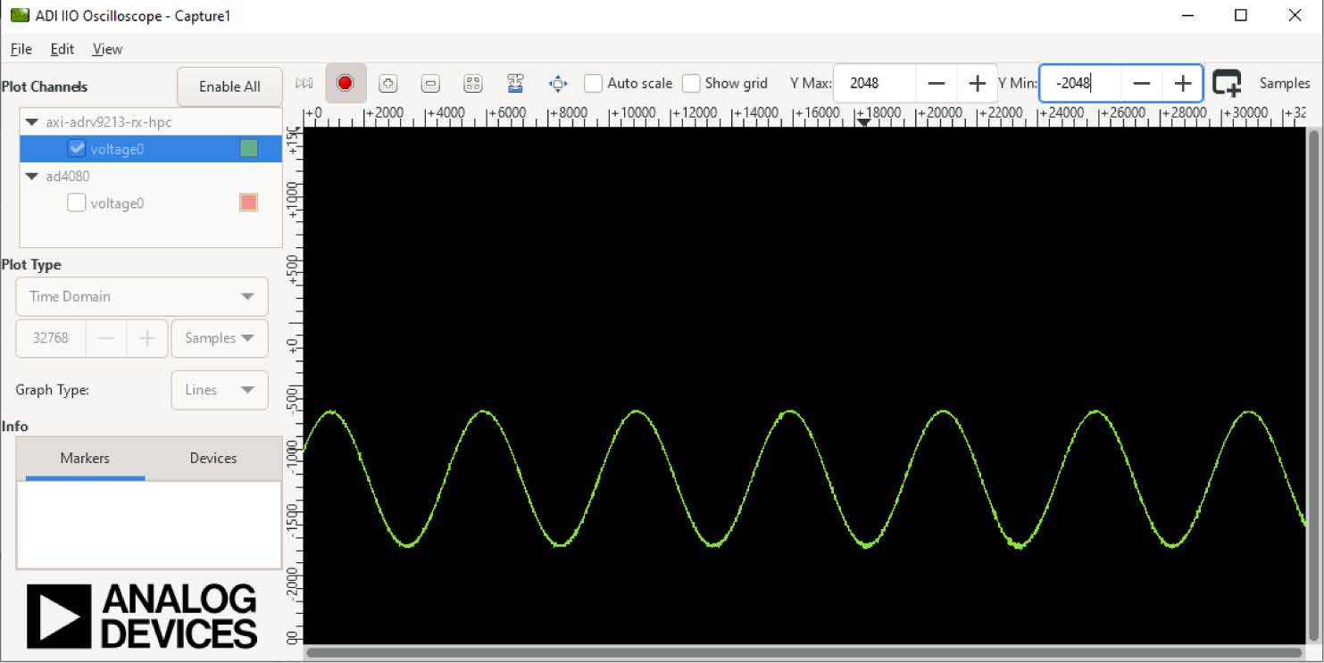
data to output_voltage0, as shown in Figure 32. To illustrate the effect of
offset shift, clear the Auto scale checkbox, set the Y max to 2048, and set the
Y min to −2048. Figures below show the AD9213 high-speed path data with the same
sinewave input but different DAC settings for offset shift.
Configure and control ADMX6001-EBZ with python scripts
Utilizing Python scripts offers advantages for configuring and controlling the
ADMX6001-EBZ board and enables data visualization and processing. Python scripts
are more efficient than the manual register read and write with IIO
Oscilloscope. The Python virtual environment (venv) for running ADMX6001-EBZ
Python scripts can be set with or without an IDE such as PyCharm. It is required
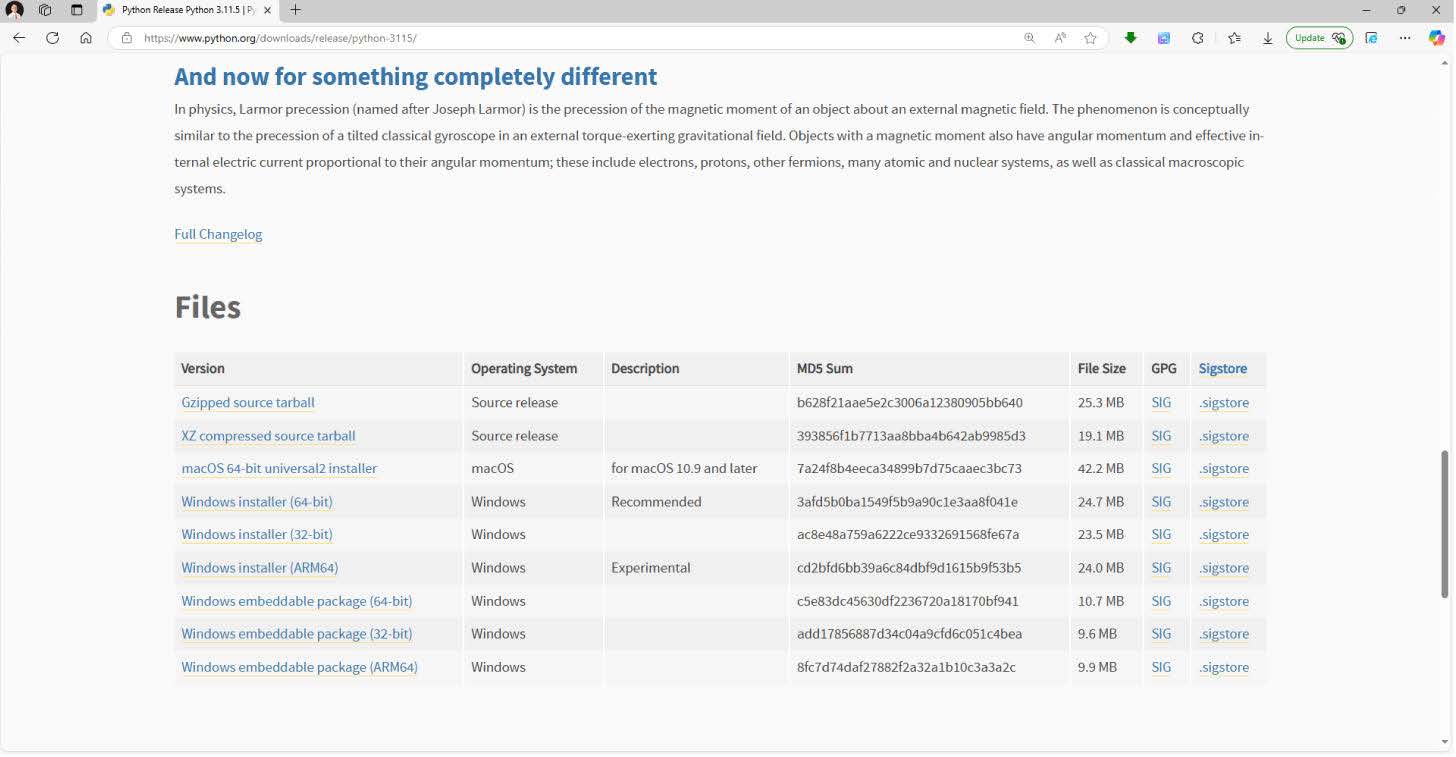
that the user installs Python 3.11.5 or a newer version and downloads the
PyADI-IIO library before proceeding to the venv setting in the following
section.
Install Python and Git for windows
Download Windows Installer (64-bit).
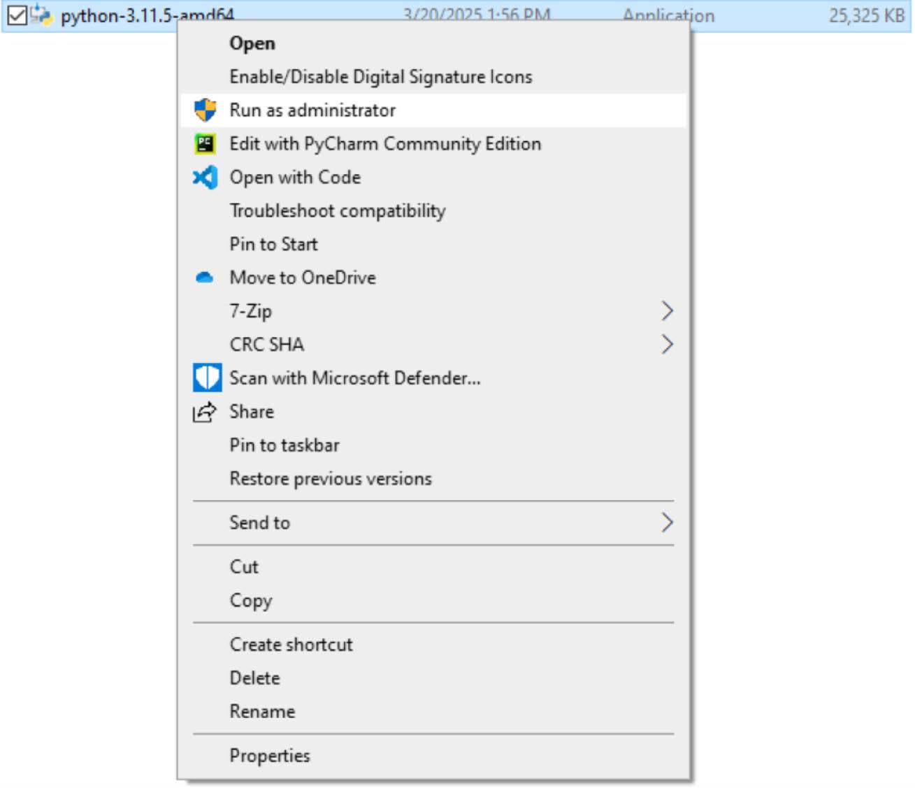
Install Python 3.11.5. It is recommended to install Python 3.11.5 as an
administrator by right clicking on the installer.
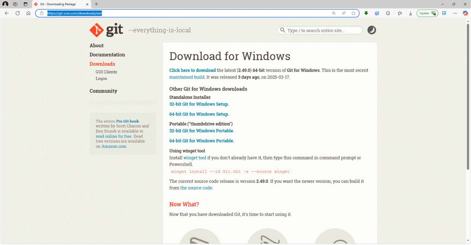
Download the 64-bit Git for Windows Setup and install Git.
Download the PYADI-IIO library
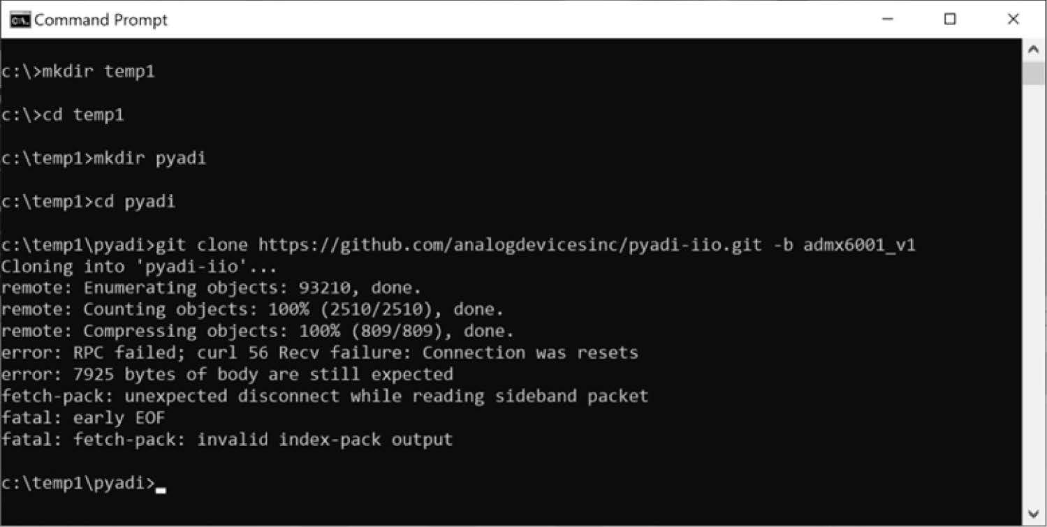
Start a Command Prompt window and clone the PyADI-IIO library for ADMX6001-EBZ.
Create and navigate to the folder for saving the PyADI-IIO library,
mkdir temp1 -> cd temp1 -> mkdir pyadi -> cd pyadi
Clone the required PyADI-IIO library from the GitHub website,
Create and configure python venv for the ADMX6001-EBZ
The venv module supports creating lightweight virtual environments, each with
their own independent set of Python packages installed in the site directories
of the virtual environments. The venv contains a specific Python interpreter,
software libraries, and binaries that are needed to support a project (library
or application).
Complete the following steps to create and activate the venv for ADMX6001-EBZ
and install the libraries:
Create a folder and copy the Python scripts to this folder, in the example
that follows C:\ADMX6001_PythonScripts.
Open a Command Prompt window and go to the Python 3.11 folder ( C:\Python311
in the following example).
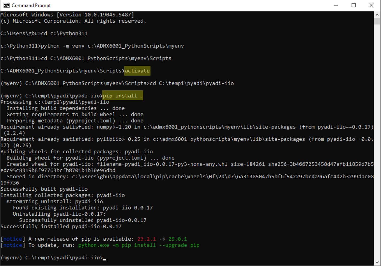
To create the venv in the Command Prompt window run the following script:
python -m venv c:\ADMX6001_Python-Scripts\myenv.
Activate the venv. Go to C:\ADMX6001_PythonScripts\myenv\Scripts>activate.
Notice the prompt changes to (myenv), indicating the venv is activated.
In the (myenv) command window, install the PyADI-IIO library. Go to the
PyADI-IIO library folder (C:\temp1\pyadi\pyadi-iio in the example) and
install pyadi-iio library: pip install.
The venv is now created and activated, and the PyADI-IIO library is installed.
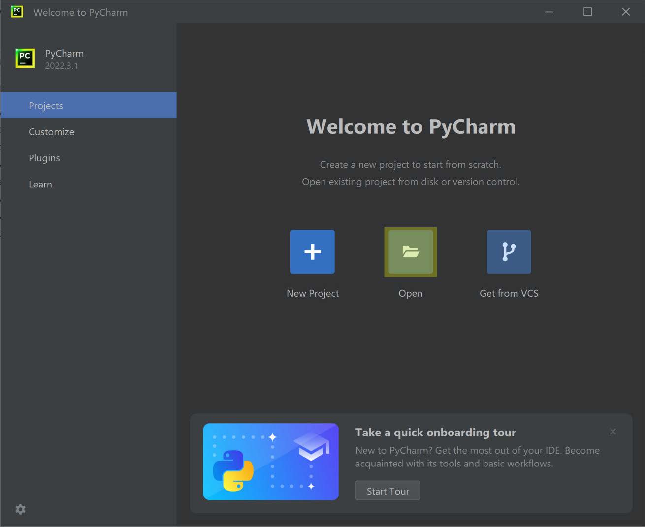
The user can also setup the venv for ADMX6001-EBZ with an integrated development
environment (IDE) such as PyCharm. To create and activate the venv, complete the
following:
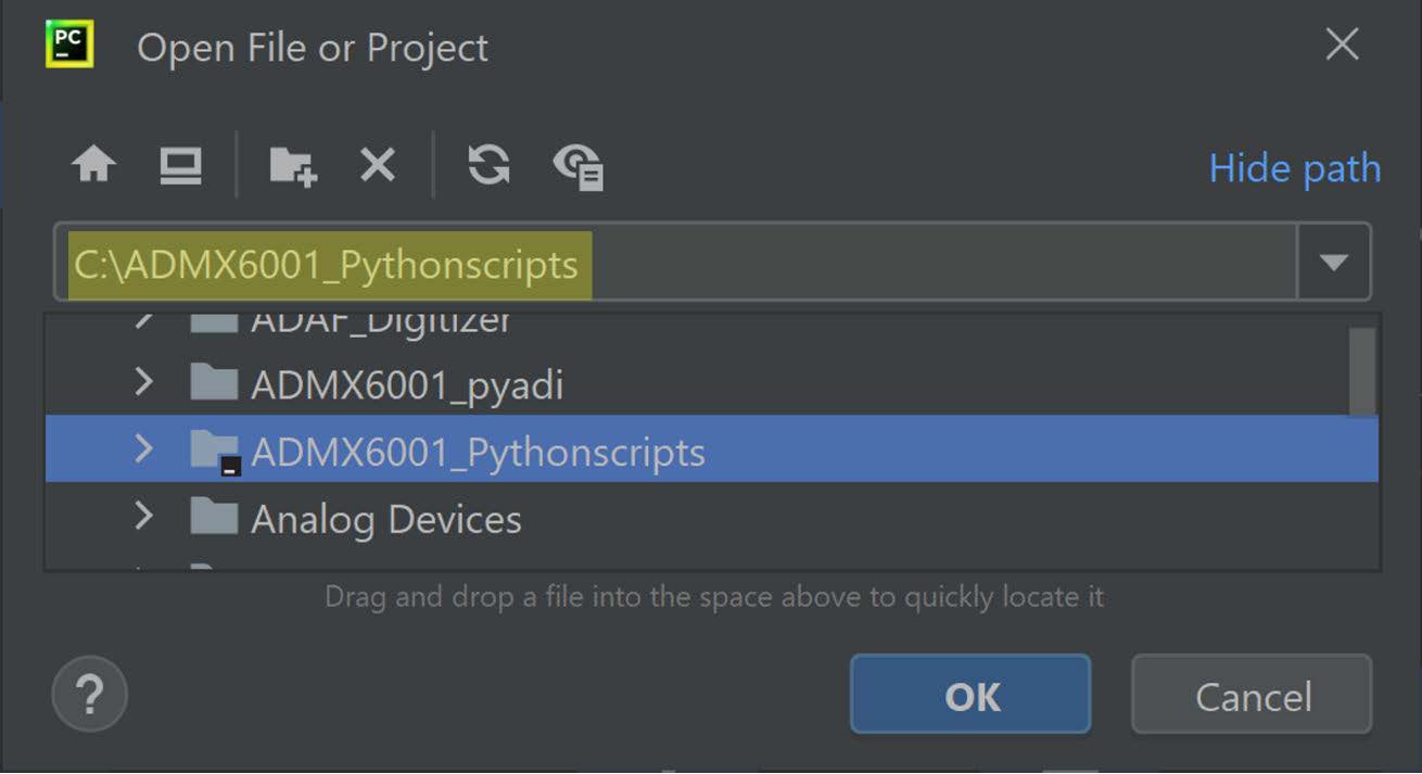
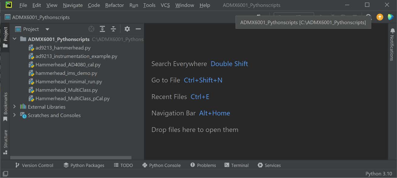
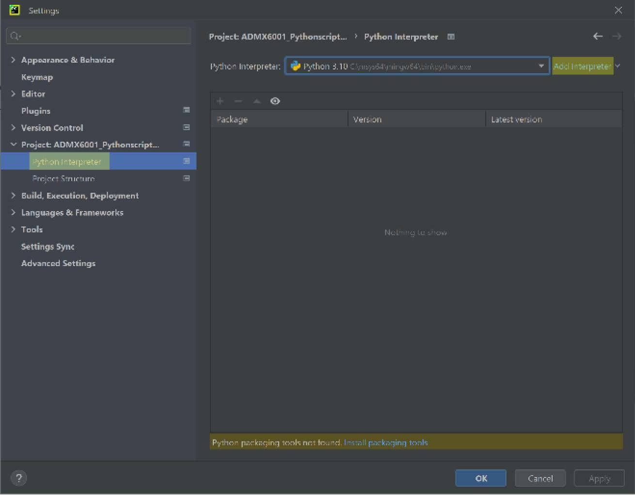
Launch PyCharm and open the ADMX6001_Pythonscripts project
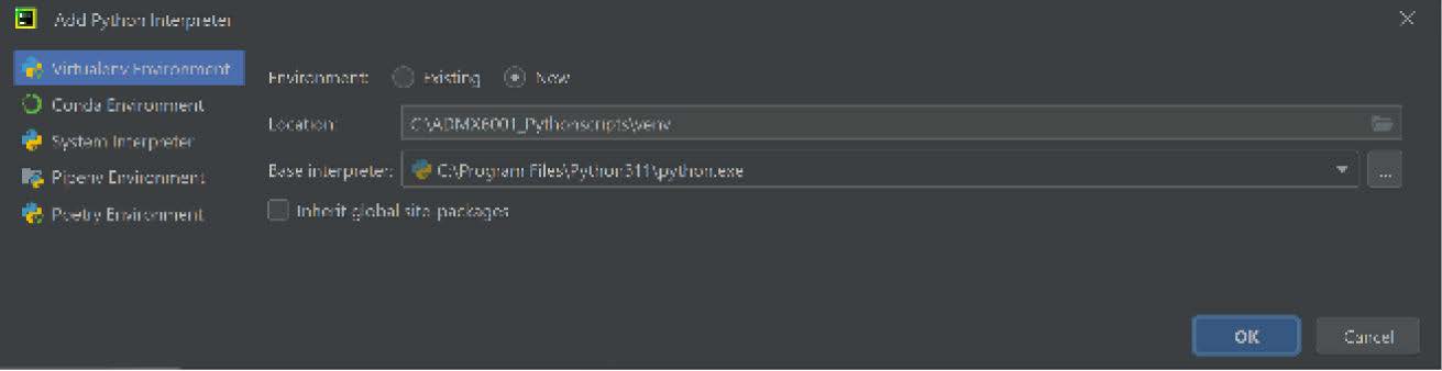
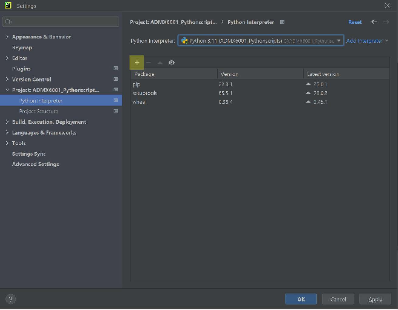
Navigate to File > Settings > Project > Python interpreter,click Add
Interpreter > Add Local Interpreter to create the venv
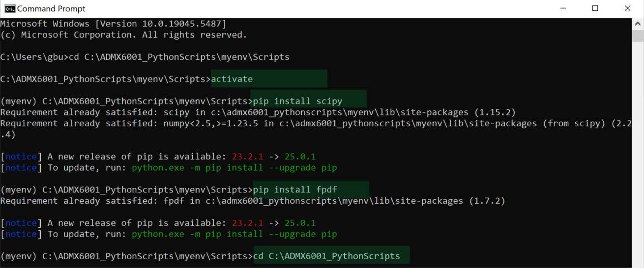
The user can add additional Python libraries in a Command Prompt window (see
the Install Additional Python Libraries section) or in PyCharm
Launch a Command Prompt window to activate venv and install the PyADI-IIO
This completes the Python venv for running Python scripts for the ADMX6001-EBZ board.
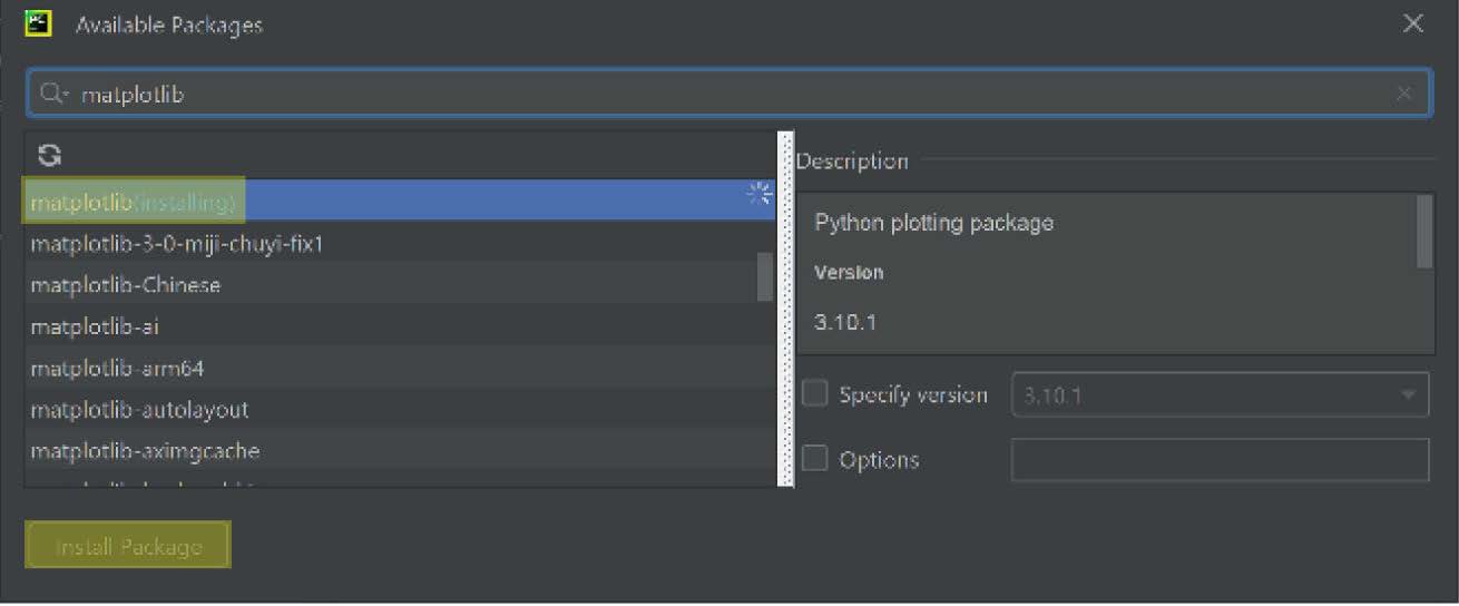
Install additional python libraries
The Python scripts for the ADMX6001-EBZ board utilize modules from various
libraries. Install these libraries, such as scipy and matplotlib, using pip
install <library name> within venv before running the Python scripts.
The Python scripts call modules in the PyADI-IIO library to initialize the
ADMX6001-EBZ board by setting required registers, JSED and LVDS data lanes, and
other control signals. Examples of Python scripts can be found at the product
page for the ADMX6001-EBZ.
Run example python scripts for the ADMX6001-EBZ
Examples of Python scripts are provided on the ADMX6001-EBZ board product page
for board evaluation. These Python scripts call modules in the PyADI-IIO library
to initialize the ADMX6001-EBZ board by setting required registers, JSED and
LVDS data lanes, and other control signals. The user is encouraged to check the
product page of the ADMX6001-EBZ board for updated and/or additional examples of
Python scripts.
The example script ADMX6001_MultiClass_pCal.py defines the classes to setup,
initiate, configure, and operate the ADMX6001-EBZ for data acquisition and
visualization. A list of useful methods defined in this script for operating the
setup of the ADMX6001-EBZ board and the Xilinx VCU118 board follows.
AD4080_CAl(self): configure the AD4080 LVDS data interface, Register 0x15 and
Register 0x16, for correct data output.
set_dac_offset(self, voltage): set the DC offset in mV for the AD9213 path.
By setting the appropriate DC offset, the signal can be moved up or down for
maximizing the dynamic range of the AD9213.
capture_data_ad9213(self, nsamples): the AD9213 captures data of nsamples at
10GSPS.
capture_data_ad4080(self, nsamples): the AD4080 captures data of nsamples at
31.25MSPS.
plot_data_ad9213(self, data): plot data captured by the AD9213.
plot_data_ad4080(self, data): plot data captured by by AD4080.
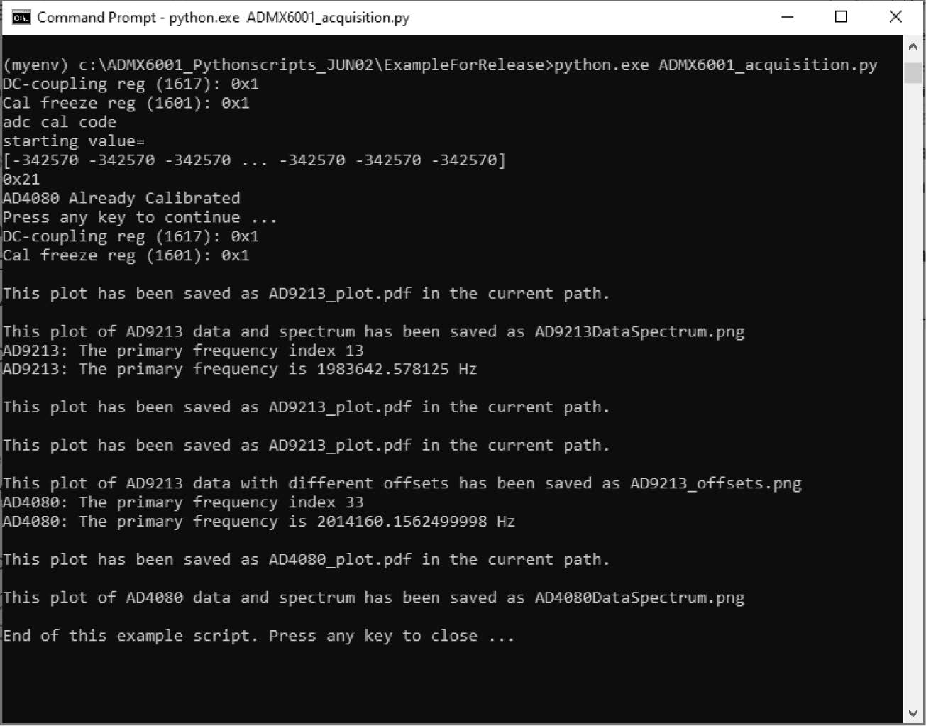
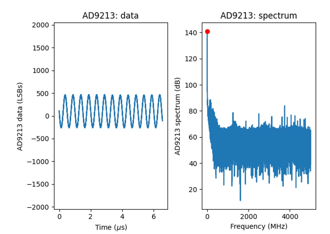
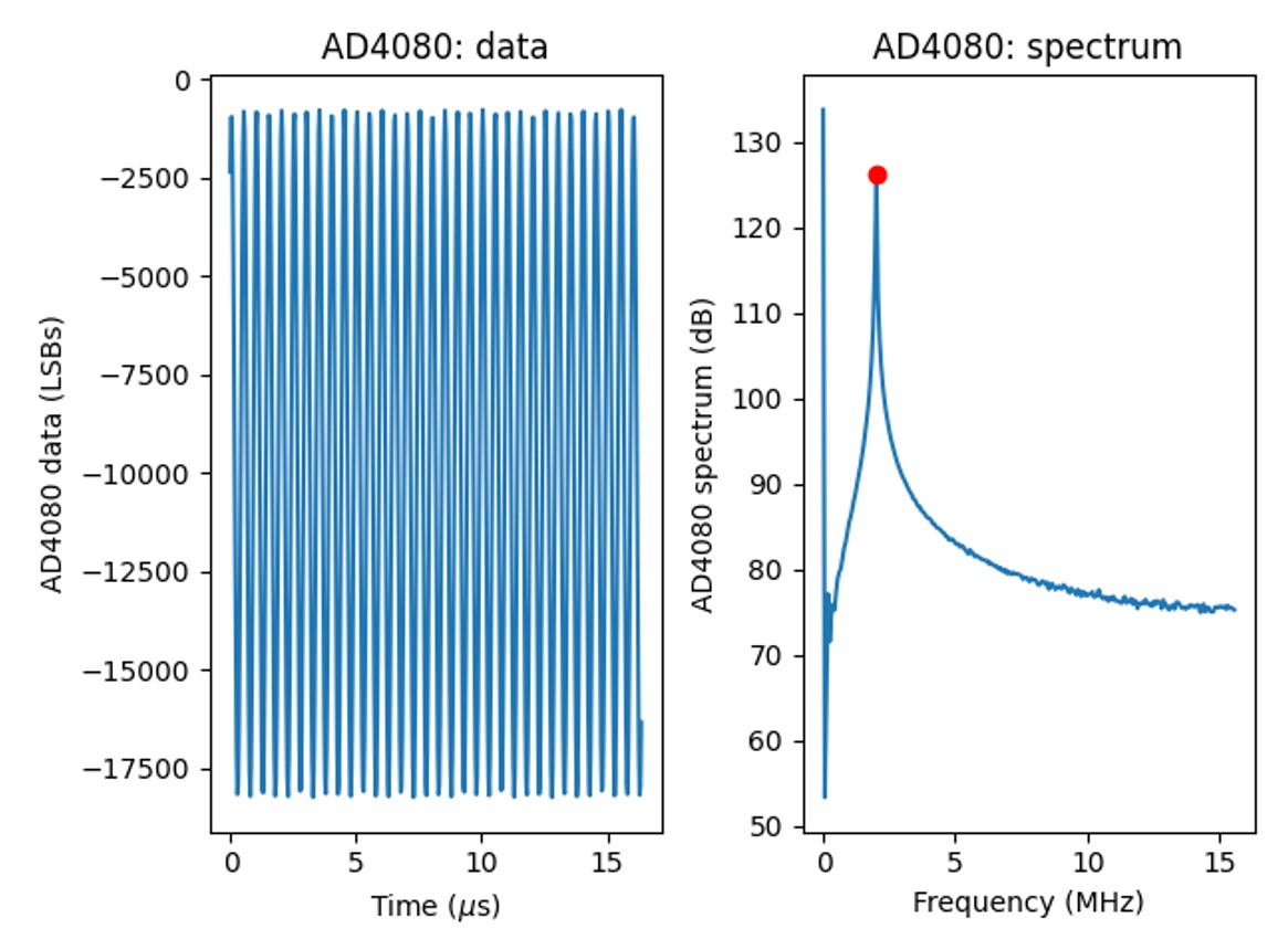
The example script ADMX6001_acquisitionl.py creates instance of classes defined
in ADMX6001_multiClass_pCal.py and calls the methods to initialize the
ADMX6001-EBZ board, calibrate the AD4080 LVDS data interface, and perform data
acquisition. Figures below the plots that the Python script
ADMX6001_acquisition.py generated.