AD7768-1 IIO Application
Introduction
This page gives an overview of using the ARM Mbed platform supported firmware example with Analog Devices EVAL-CN0540-ARDZ Evaluation board(s) that contains AD7768-1 and SDP-K1 controller board. This example code leverages the ADI developed IIO (Industrial Input Output) ecosystem to evaluate the AD77681 device by providing a device debug and data capture support.
The AD7768-1 is a low power, high performance, Σ-Δ analog-to-digital converter (ADC), with a Σ-Δ modulator and digital filter for precision conversion of both ac and dc signals. The AD7768-1 is a single-channel version of the AD7768, an 8-channel, simultaneously sampling, Σ-Δ ADC.
Useful Links
Hardware Connections
SDP-K1:
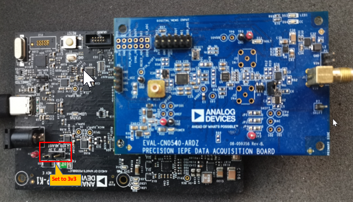
Place EVAL-CN0540 on top of the SDP-K1 to communicate with the AD7768-1 IC.
Locate VIO_ADJUST Pin Headers near the DC Connector, set it to 3.3V. (Default is 1.8 V)
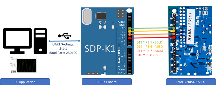
Connection Details:
Refer to useful links for the SDP-K1, AD7768-1 IC and EVAL-CN0540-ARDZ board, schematics and pin description.
Software Downloads
IIO Oscilloscope (Client)
This is a GUI (Graphical User Interface) based IIO client application for data visualization and device configuration/debugging. The data from IIO devices (ADCs/DACs) is transmitted over Serial/Ethernet/USB link to IIO Oscilloscope client through the abstracted layer of “libiio”. Download and install below IIO Oscilloscope windows installer in your computer.
Download
IIO Oscilloscope installer for Windows (Use below link):
Evaluating AD7768-1 Using IIO Ecosystem
Running IIO Oscilloscope ( Client )
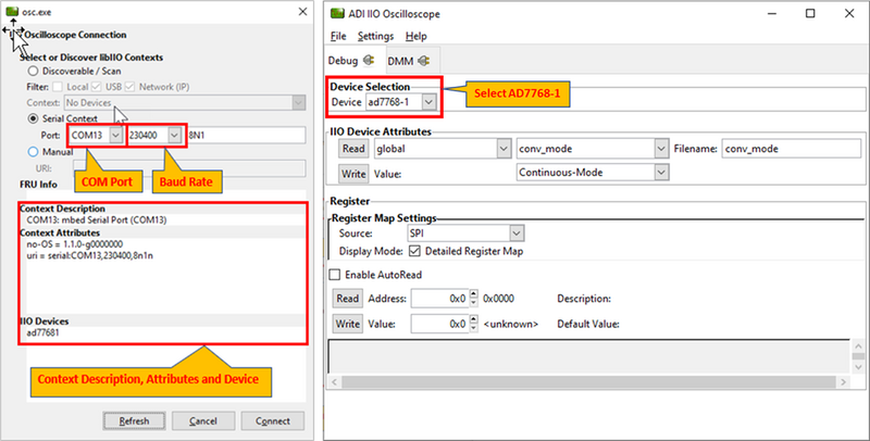
Open the IIO Oscilloscope application from start menu and configure the serial context settings as shown below in the image.
Click on the refresh button, the context description and the attributes will be populated by the serial details and the AD7768-1 device should pop-up in IIO devices list.
Click ‘Connect’ and a new window will pop-up.
On the new window, select the AD7768-1 device from the drop down menu list of ‘Device Selection’.
Configure/Access IIO Device Attributes ( Parameters )
The IIO Oscilloscope’s Device Attributes allows user to access and configure different device parameters.
There are 2 types of attributes:
Device Attributes (Global): Access/Configure common device parameters. (e.g. Conversion Mode, Sampling Frequency)
Channel Attributes (Specific to channels): Access/Configure channel specific device parameters. (e.g. channel raw and scale)
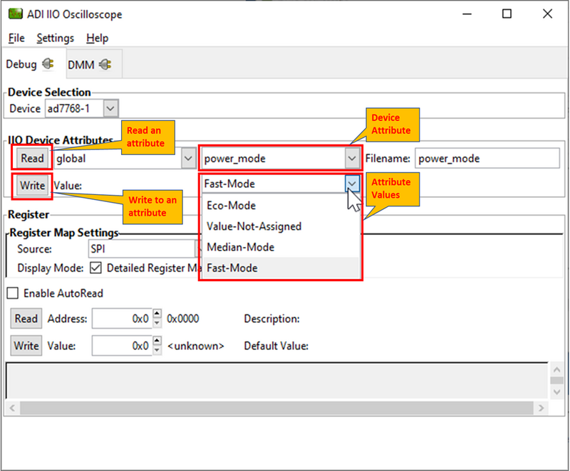
How to read and write attribute:
To ‘Read’ an attribute, simply select the attribute from a list or press ‘Read’ button on left side.
To ‘Write’ an attribute, write a attribute value in the ‘value field’ and press ‘Write’ button. The value to be written corresponds to expected bit-field for that parameter, specified in the datasheet. For example, below figure shows how to write a “Power Mode” value.
Using Register Map Settings to read register values
How to read and write register values:
To read a register, simply populate the Address textbox with the desired address to be read and press the Read button on the left side.
To write a register, populate the Address textbox with the desired address and populate the Value text box with the value based on the datasheet, then press the Write button on the left.
To auto-read a register, tick the Enable AutoRead check box and populate the Address textbox with the desired address to be read.
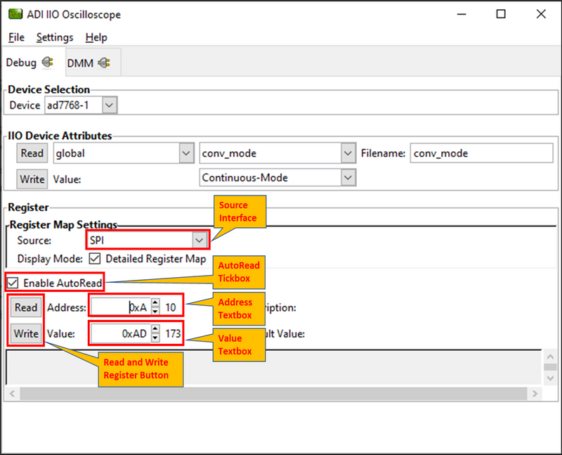
Note
Unused or Unavailable register address will return as an error.
Using DMM Tab to Read DC Voltage on Input Channels
DMM tab can be used to read the instantaneous voltage applied on analog input channels. Simply select the device and channels to read and press start button.
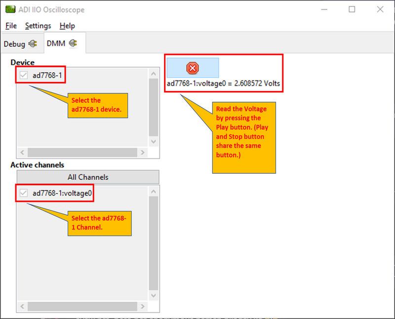
Note
The voltage is just instantaneous, so it is not possible to get RMS AC voltage or averaged DC voltage. Also, when using DMM tab, it is not encouraged to use Data Capture or Debug tab as this could impact data capturing.
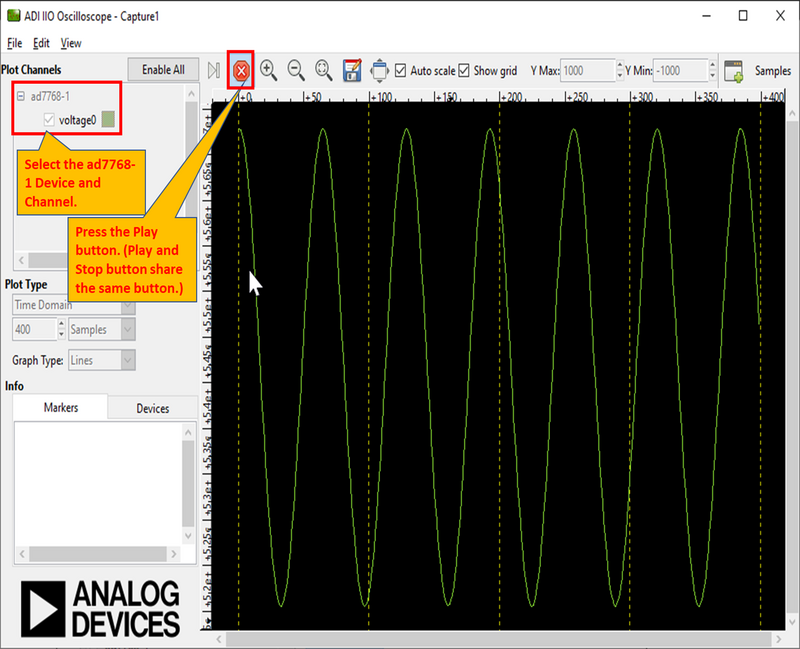
Data Capture from IIO Device
To capture the data from AD7768-1 IIO device, simply select the device and channels to read/capture data. The data is plotted as “ADC Raw Value” Vs “Number of Samples” and is just used for Visualization. The data is read as is from device without any processing. If user wants to process the data, it must be done externally by capturing data from the Serial link on controller board.
Time Domain Plot:
Frequency Domain Plot:
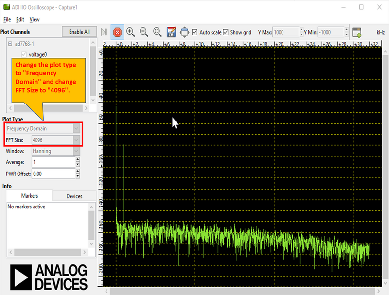
Note
The DMM or Debug tab should not be accessed when capturing data as this would impact data capturing. More info here: data-capture-using-iio-app
Important
The continuous time domain data capture can work correctly at ODR/Sampling Rate defined in the firmware code (32KSPS). For plotting frequency domain response max 4096 samples can be selected due to limited buffer size in the firmware. These limitations are due to the firmware architecture and design choices and do not limit the actual device specifications provided in device datasheet
Modifying Firmware
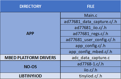
The below block diagram shows the AD7768-1 IIO firmware layer.
app_config.h
This file can be used to:
Set the default active device to AD7768-1.
Set the serial communication between UART or Virtual COM port.
app_config_mbed.h
This file can be used to:
Configure Mbed related pin configurations.
Configure the pin mapping of AD7768-1 w.r.t Arduino Header on Controller Board.
ad77681_user_config.c
This file defines the user configurations for the AD7768-1, such as SPI parameters (frequency, mode, etc) and other init parameters used by No-OS drivers to initialize AD7768-1 device (e.g. Power Mode, Conversion mode, etc). These are the parameters loaded into device when device is powered-up or power-cycled.
ad77681_iio.c
This file defines getter/setter functions for all the device and channel specific attributes (related to AD7768-1 devices) to read/write the device parameters. The majority of device specific functionality is present in this module.
ad77681_data_capture.c
This file defines the data capture implementation of AD7768-1 for visualizing adc raw data on IIO oscilloscope.
No-OS Drivers for ad77681
The no-OS drivers provide the high level abstracted layer for digital interface of AD7768-1 devices. The complete digital interface (to access memory map and perform data read) is done in integration with platform drivers.
The functionality related with no-OS drivers is covered in below 2 files:
ad77681.c
ad77681.h
Tip
It is hoped that the most common functions of the AD7768-1 are coded, but it’s likely that some special functionality is not implemented. Feel free to consult Analog Devices Engineer-Zone for feature requests, feedback, bug-reports etc.