ADRD4161-01Z Quick Start Guide
Required Hardware
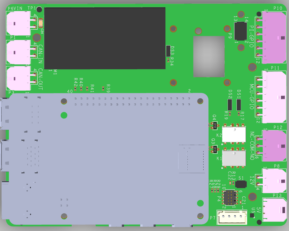
ADRD4161-01Z
Raspberry Pi 5 (or compatible embedded compute platform)
MicroSD card (16 GB or larger recommended)
DC power supply (9-70 V DC)
Compatible ADIS16xxx IMU module (optional)
CAN cable (optional)
Optional: MAX32625PICO (or compatible) debug/programming probe
Getting Started
The ADRD4161-01Z module comes with slcan firmware already flashed on the MAX32662 MCU.
Flash Raspberry Pi OS to the MicroSD card using Raspberry Pi Imager
Insert the MicroSD card into the Raspberry Pi
Mount the Raspberry Pi 5 onto the ADRD4161-01Z 40-pin header
Connect an ADIS16xxx IMU module to the 14-pin or 16-pin connector (optional)
Connect the CAN bus cable if using CAN communication (optional)
Connect the 9-70 V DC power supply
Configure Device Tree Overlays
Boot the Raspberry Pi and configure the required device tree overlays.
For CAN bus support, add to /boot/firmware/config.txt:
[all]

# UART0 slcan
dtoverlay=uart0,ctsrts
For IMU support (example for ADIS16470), add:
[all]

# ADIS16470 IMU
dtoverlay=rpi-regulator
dtoverlay=adis16475,device=adis16470,drdy_pin=4,reset_pin=25,sync_mode=0
Disable the serial console in /boot/firmware/cmdline.txt by changing
console=serial0,... to console=tty1.
Reboot the Raspberry Pi after making changes.
Verify the Setup
CAN Bus
Start the slcan daemon and bring up the interface:
sudo slcand -o -c -f -t hw -S 2000000 -s 6 /dev/ttyAMA0 can0
sudo ip link set can0 type can bitrate 500000
sudo ip link set can0 up
Verify the interface is up:
ip link show can0
If connected to other CAN devices (e.g. ADRD3161-01Z, ADRD5161-01Z),
you should see CAN traffic using candump:
candump can0
IMU
Verify the IMU is detected:
iio_info -u local:
Read accelerometer data:
iio_readdev -u local: adis16470 accel_x
Next Steps
See ADRD4161-01Z Hardware Guide for detailed connector and jumper information
See ADRD4161-01Z Software Guide for advanced configuration options