ADRD4161-01Z
Robotics Perception Compute Carrier
Introduction
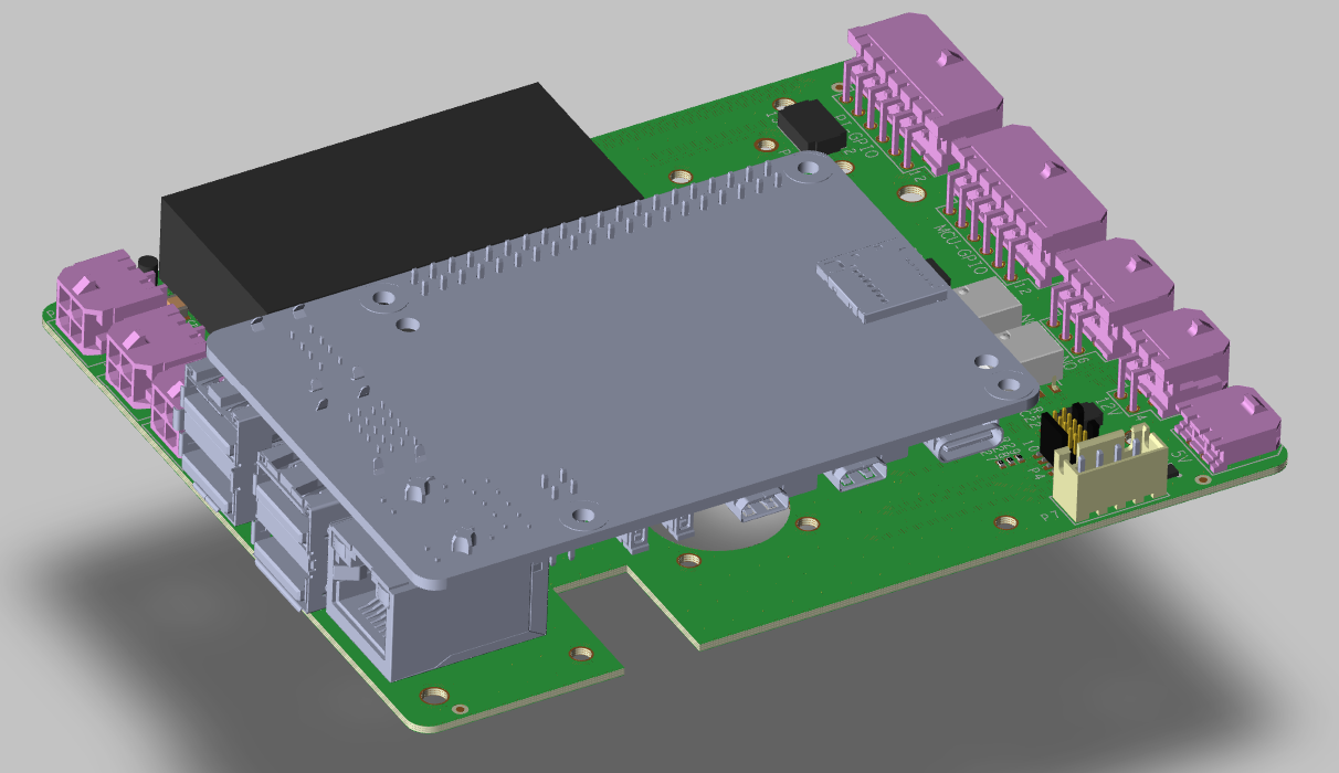
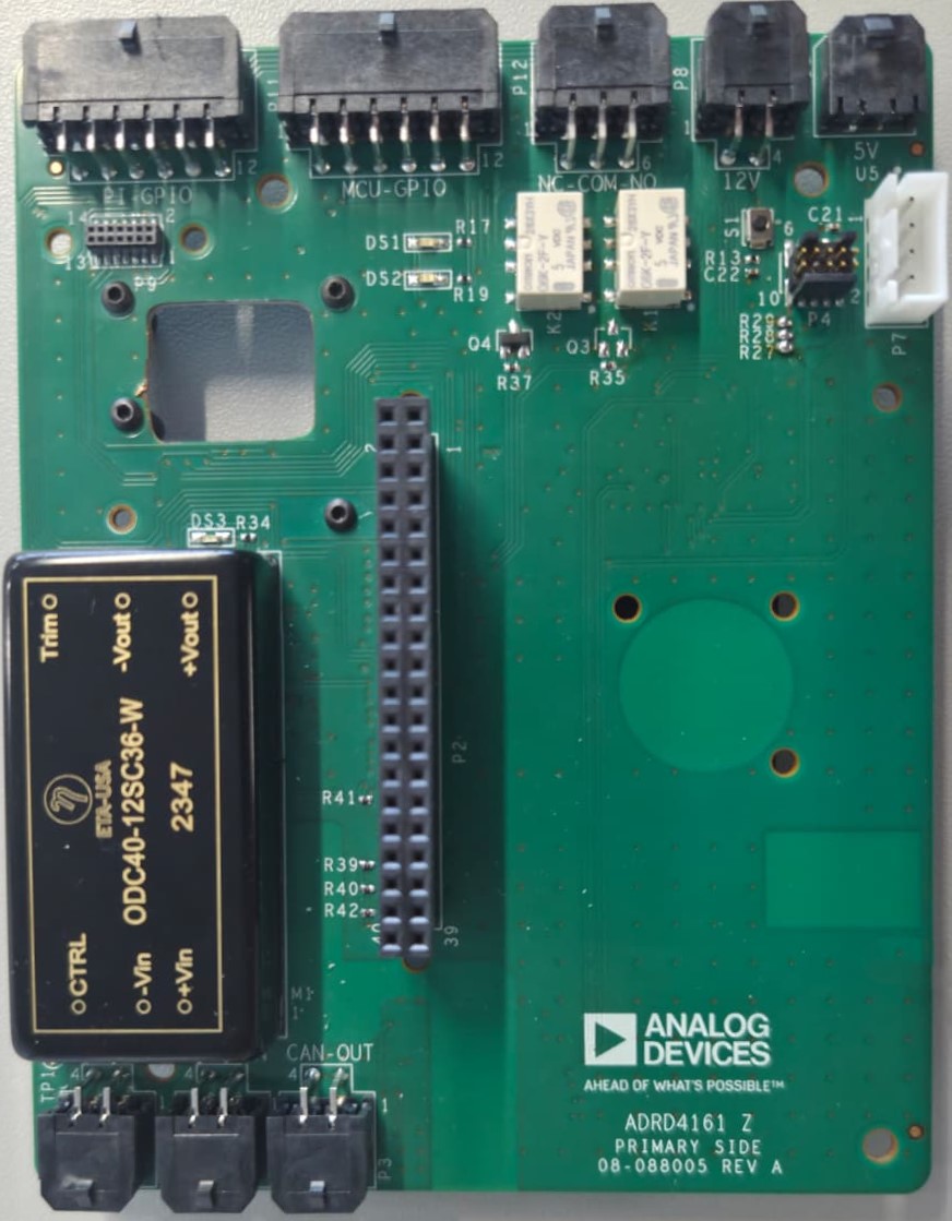
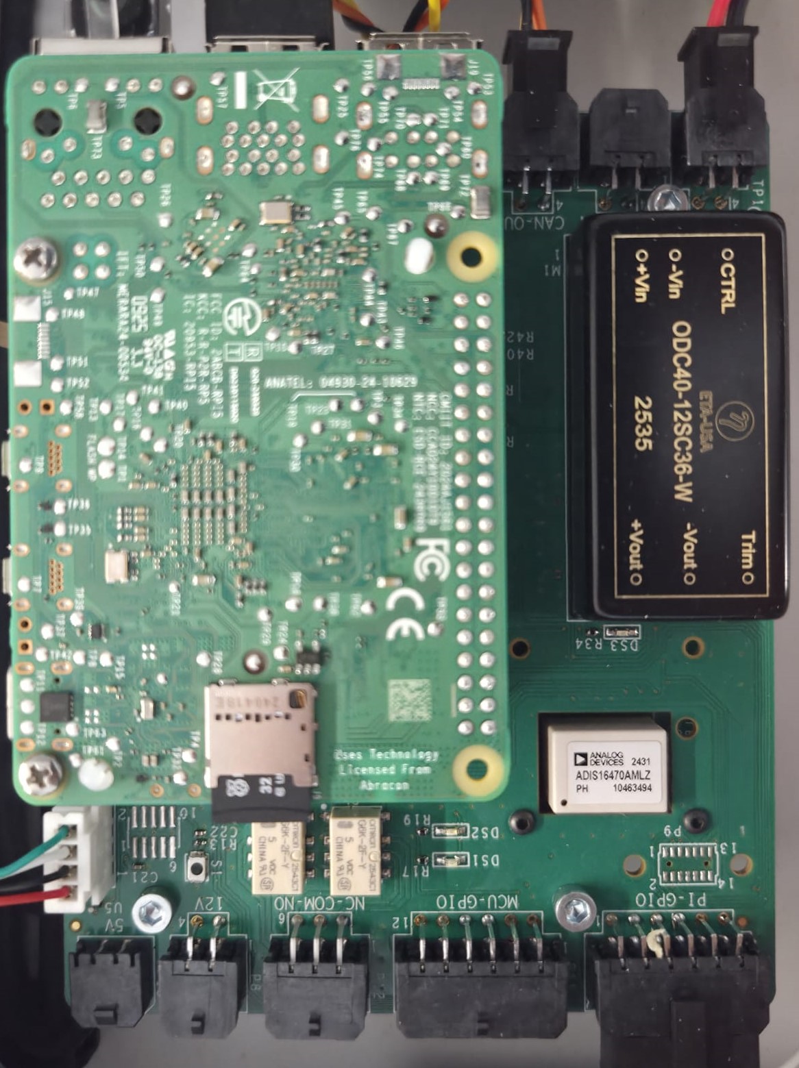
The ADRD4161-01Z is a robotics perception embedded compute carrier board designed for platforms such as Raspberry Pi 5 and Nvidia Jetson/Orin/AGX, featuring the Raspberry Pi 40-pin header. It provides isolated power supplies and a number of connectivity options: ADI IMU, CAN 2.0B, UART, GPIOs, and two SPDT relays.
Its isolated DC-DC converter can be powered from 9-70 V DC, which it then converts to 12 V (3 A limit) system voltage and 5 V (5 A limit) for the Raspberry Pi and power-hungry USB peripherals. 14-pin and 16-pin IMU connectors allow for plug-and-play interoperability with compatible IMU modules in the ADIS16xxx series.
Specifications
Isolated 9-70 V DC input
Isolated power supply provides 12 V 3 A and 5 V 5 A
Raspberry Pi 40-pin header
IMU connectors compatible with 14-pin and 16-pin ADIS16xxx IMU modules
Isolated CAN 2.0B controller, with slcan adapter firmware out of the box
2x SPDT relays, 1 A
Supporting hardware:
MAX32662 Arm Cortex-M4 Processor with FPU-Based Microcontroller (MCU) with 256KB Flash and 80KB SRAM
ADM3053 Signal and Power Isolated CAN Transceiver with Integrated Isolated DC-to-DC Converter
Connections:
Power input: 9-70 V DC screw terminal
Compute header: Raspberry Pi 40-pin
IMU: 14-pin and 16-pin connectors (ADIS16xxx compatible)
CAN, isolated: Custom connector (directly on MCU via slcan)
UART: Header P7 (UART4 + switchable 5 V)
GPIOs: Header P10
Relays: Header P12 (2x SPDT, 1 A)
Programming/debugging: SWD via solder jumpers
Required Hardware
Raspberry Pi 5 (or compatible embedded compute platform with 40-pin header)
Compatible ADIS16xxx IMU module (optional)
DC power supply (9-70 V DC)
MicroSD card with Raspberry Pi OS
To debug/reprogram the onboard MCU, you will need a MAXDAP compatible debug probe, such as the MAX32625PICO.
System Setup
The module comes with slcan firmware flashed on the MAX32662 MCU.
To set the system up:
Mount the Raspberry Pi 5 onto the 40-pin header
Connect an ADIS16xxx IMU module (optional)
Connect the CAN bus cable (if using CAN communication)
Connect the 9-70 V DC power supply
Configuration of device tree overlays is required before using the IMU and CAN interfaces. See the ADRD4161-01Z Quick Start Guide for initial setup instructions.
User Guides
Help and Support
For questions and more information about this product, connect with us through the Analog Devices EngineerZone.