ADRD4161-01Z Hardware Guide
|
|
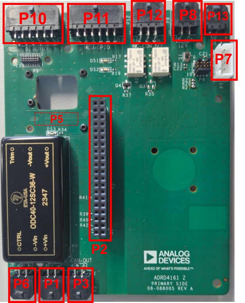
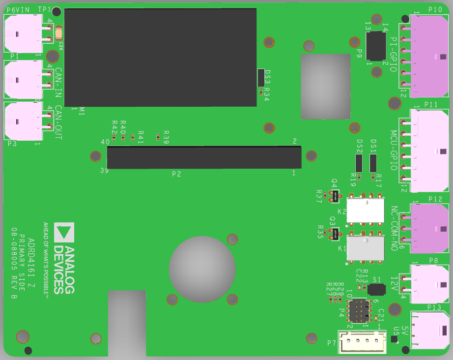
Board Layout
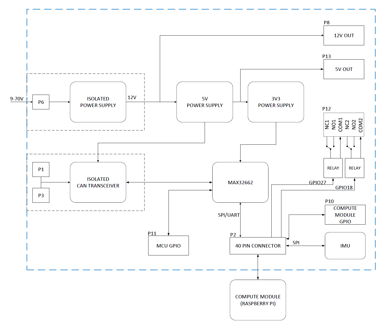
Block Diagram
Connectors
Power Input (P6)
The board accepts 9-70 V DC input on P6 through an isolated DC-DC converter (ODC40-12SC36-W), which provides:
12 V at up to 3 A for system voltage (P8)
5 V at up to 5 A for the Raspberry Pi and USB peripherals (P13)
Raspberry Pi Header (P2)
Standard 40-pin Raspberry Pi header for connecting compatible embedded compute platforms (Raspberry Pi 5, Nvidia Jetson/Orin/AGX, etc.).
IMU Connectors (P5)
Two IMU connectors provide plug-and-play compatibility with ADIS16xxx series IMU modules:
P5 (Secondary side): 14/16-pin connector
UART Header (P7)
Exposes the Raspberry Pi’s UART4 interface and a switchable 5 V supply (controlled by GPIO 24). The 5 V supply is switched via an ADP198 load switch.
Pin |
Signal |
Description |
|---|---|---|
1 |
5V_SW |
Switchable 5 V (GPIO 24 enable) |
2 |
GND |
Ground |
3 |
UART4_TXD |
GPIO 12 (UART4 TX) |
4 |
UART4_RXD |
GPIO 13 (UART4 RX) |
PI-GPIO Header (P10)
Exposes Raspberry Pi GPIO pins, including GPIO 23 (pin 11) for WS2812 LED control.
Pin |
Signal |
Description |
|---|---|---|
1 |
5V |
5 V supply |
2 |
3V3 |
3.3 V supply |
3 |
SDA |
I2C data |
4 |
GPIO26 |
General purpose I/O |
5 |
GPIO22 |
General purpose I/O |
6 |
GPIO20 |
General purpose I/O |
7 |
GND |
Ground |
8 |
GND |
Ground |
9 |
SCL |
I2C clock |
10 |
GPIO6 |
General purpose I/O |
11 |
GPIO23 |
WS2812 LED data |
12 |
GPIO21 |
General purpose I/O |
MCU-GPIO Header (P11)
Exposes MAX32662 microcontroller GPIO pins.
Pin |
Signal |
Description |
|---|---|---|
1 |
5V |
5 V supply |
2 |
3V3 |
3.3 V supply |
3 |
MCU_GPIO1 |
MCU general purpose I/O |
4 |
MCU_GPIO3 |
MCU general purpose I/O |
5 |
MCU_SDA |
MCU I2C data |
6 |
NC |
Not connected |
7 |
NC |
Not connected |
8 |
MCU_SCL |
MCU I2C clock |
9 |
MCU_GPIO2 |
MCU general purpose I/O |
10 |
NC |
Not connected |
11 |
GND |
Ground |
12 |
GND |
Ground |
Relay Header (P12)
Exposes contacts for two SPDT relays (K1, K2), each rated for 1 A.
Pin |
Signal |
Description |
|---|---|---|
1 |
NC1 |
K1 Normally Closed |
2 |
COM1 |
K1 Common |
3 |
NO1 |
K1 Normally Open |
4 |
NC2 |
K2 Normally Closed |
5 |
COM2 |
K2 Common |
6 |
NO2 |
K2 Normally Open |
Relay control GPIOs:
Relay |
GPIO |
P12 NC Pin |
P12 Common Pin |
P12 NO Pin |
|---|---|---|---|---|
K1 |
17 |
1 |
2 |
3 |
K2 |
18 |
4 |
5 |
6 |
CAN Connectors (P1, P3)
The ADRDx161 board family communicates via CAN bus. The CAN interface on the ADRD4161-01Z is directly connected to the onboard MAX32662 MCU running slcan firmware. P1 (CAN-IN) and P3 (CAN-OUT) allow for daisy-chaining CAN devices.

Solder Jumpers
R27, R28, R29 - SWD Debug
When bridged, these jumpers expose the MAX32662 microcontroller’s SWD signals on the Raspberry Pi’s GPIOs for programming and debugging:
Jumper |
Signal |
Pi GPIO |
|---|---|---|
R27 |
SWD_IO |
6 |
R28 |
SWD_CLK |
20 |
R29 |
SWD_RSTN |
21 |
Onboard Components
MAX32662 Microcontroller
The MAX32662 handles CAN communication via the slcan protocol. It can be reprogrammed through SWD when the appropriate solder jumpers are bridged.
See ADRD4161-01Z Software Guide for reprogramming instructions.
Relays
Two SPDT relays (K1, K2) rated for 1 A, controlled via Raspberry Pi GPIOs:
K1: GPIO 17
K2: GPIO 18
Design Support Files
A design support package consisting of the board schematic, layout, assembly and fabrication files, and more, can be downloaded from the ADRD4161-01Z page.