EVAL-LTC4306
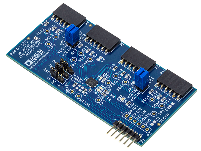
LTC4306 Evaluation Board with PMOD Connectors on Both Upstream and Downstream
Overview
The EVAL-LTC4306 features the LTC4306, a 4-channel, 2-wire I2C bus and SMBus-compatible multiplexer, which has bus buffers that provide capacitive isolation between the upstream bus and downstream buses.
This evaluation board provides 6-pin PMOD connectors for upstream and downstream connection for compatibility with PMOD form factors such as EVAL-ADICUP3029, an Arduino-based wireless development platform for Internet of Things applications based on an ultralow power ARM Cortex-M3 processor.
The EVAL-LTC4306 comes with PMOD connectors and 10 kΩ pull up resistors on both the upstream and downstream side, and 0.1 µF bypass capacitor on the upstream side. The user also has the option to add a 6-pin, 2.54 mm pitch pin header for connection to the GPIO pins for added functionality.
The user can also add test points on different places on the board for fault monitoring and place additional bypass capacitors (0805 size footprint) on the upstream and the downstream side for defense against any unwanted noise in their system and for adequate bypassing on power supply lines.
Features
Features LTC4306, a 4-channel, 2-wire I2C bus and SMBus compatible multiplexer having bus buffers that provide capacitive isolation between the upstream bus and downstream buses.
6-pin PMOD connectors for upstream and downstream connection for compatibility with PMOD form factors such as EVAL-ADICUP3029 (Arduino based Wireless Development Platform based on an ultra-low power ARM Cortex-M3 processor) or with EVAL-SDP-CK1Z (SDP-K1 Cortex ARM core processors Controller Board and color sensor)
Applications
Nested Addressing
5V/3.3V Level Translator
Capacitance Buffer/Bus Extender
Evaluating the EVAL-LTC4306
ADI no-OS
The goal of ADI Microcontroller no-OS is to provide reference projects for lower end processors, which can’t run Linux or aren’t running a specific operating system, and to help those customers using microcontrollers with ADI parts. ADI No-OS offers generic drivers, which can be used as a base for any microcontroller platform and also example projects, which are using these drivers on various microcontroller platforms.
For more information about ADI no-OS and supported microcontroller platforms, visit the No-OS User Guide found here.
LTC4306 no-OS Driver
Information about the LTC4306 driver can be found here: LTC4306 no-OS Driver
No-OS Supported Platforms
Maxim Platform
Hardware Setup
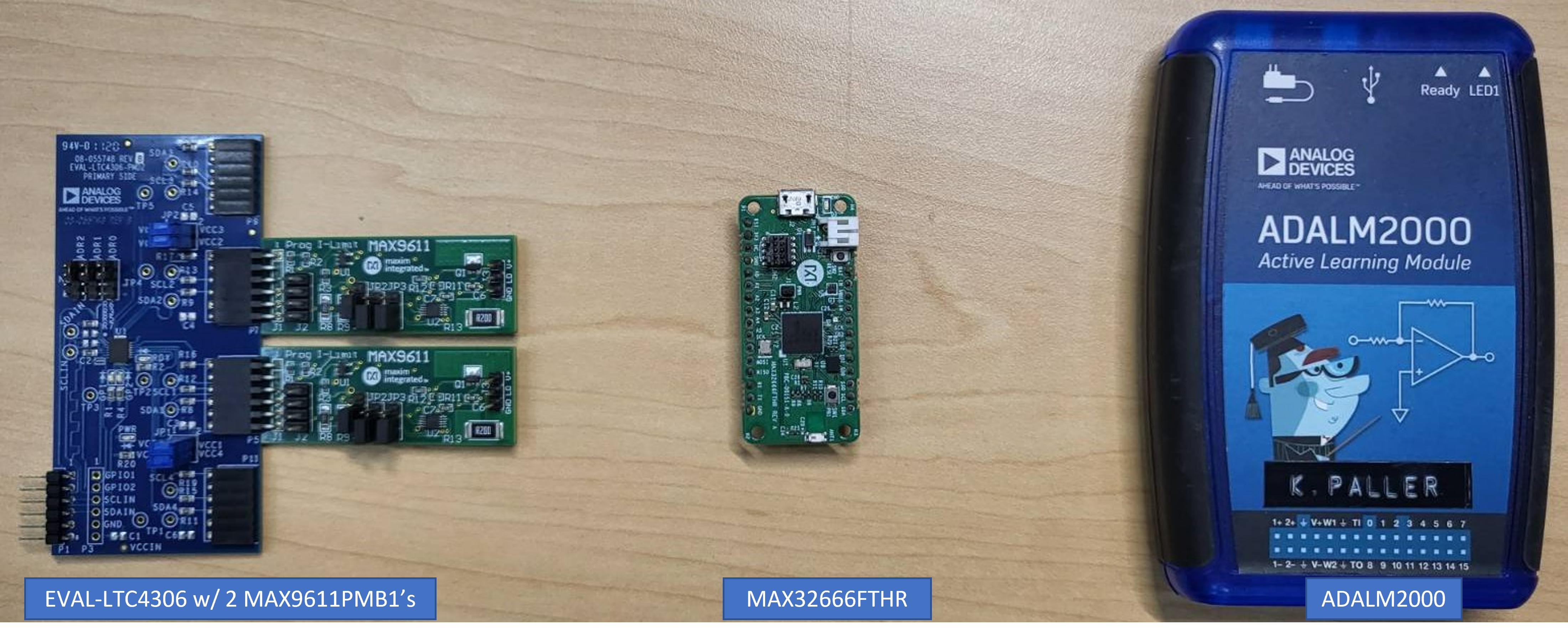
Required Hardware
Required Connections
The MAX32666FTHR does not have a PMOD interface, but you may use Dupont female-female cables to make the required connections. The table below shows the connection between EVAL-LTC4306 and MAX32666FTHR.
EVAL-LTC4306 Pin Number (P3) |
MAX32666 Pin Number |
Function |
Mnemonic |
|---|---|---|---|
VCC |
3V3 |
3.3 V Supply (for IO) |
3V3 |
GND |
GND |
Board Ground |
GND |
SCLIN |
SCL |
Serial Clock |
SCL |
SDAIN |
SDA |
Serial Data |
SDA |
Once the EVAL-LTC4306 and MAX32666FTHR are connected, the MAX9611PMB1’s can be connected to the LTC4306 channels via the PMOD connectors. Secure the connections to ensure proper and continuous operation of the setup.
For Maxim platforms, the following UART settings are used:
Speed |
57600 |
Data Bits |
8 |
Stop Bits |
1 |
Parity |
None |
Flow Control |
None |
ADuCM3029 Platform
Hardware Setup
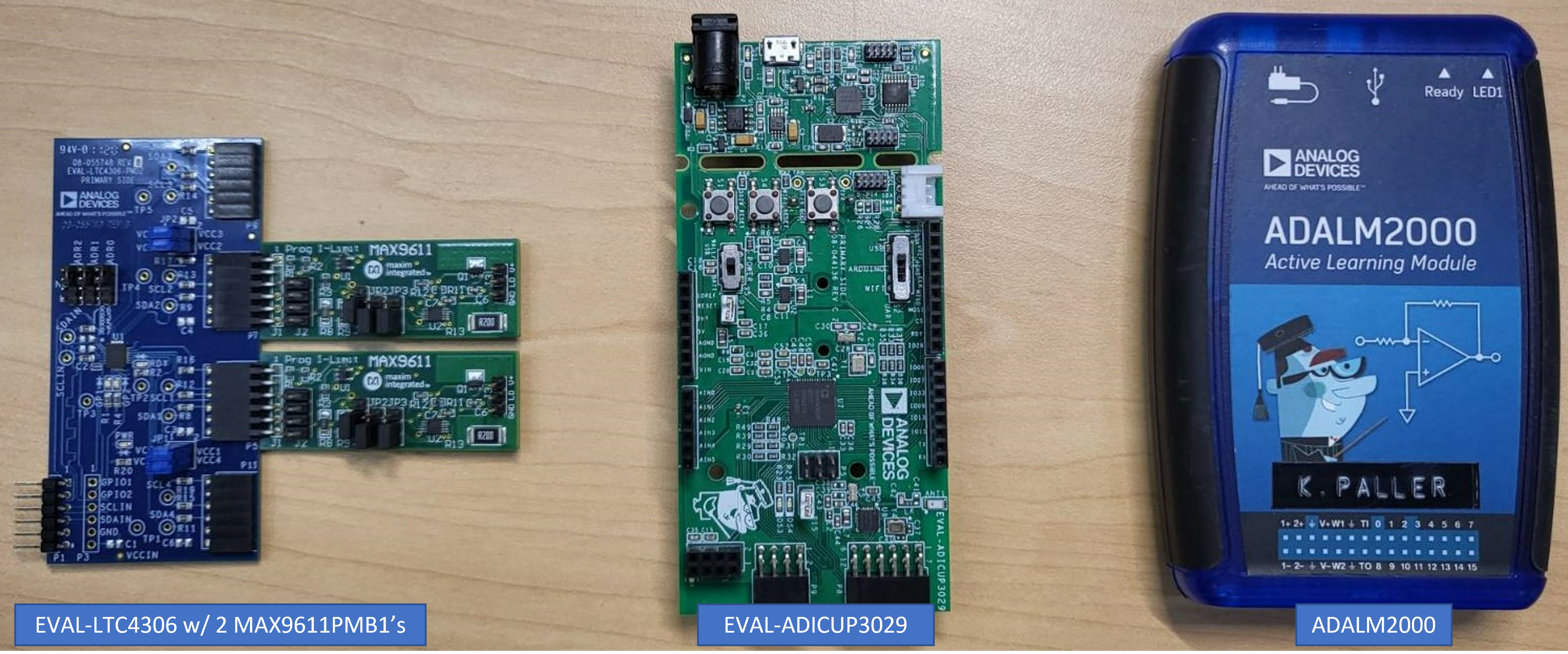
Required Hardware
Required Connections
Connect the EVAL-LTC4306 via the EVAL-ADICUP3029’s PMOD I2C headers (8 pins, P9). Once connected, attach the MAX9611PMB1’s to one or more channels. Secure the connections to ensure proper and continuous operation of the setup.
For ADuCM3029 platform, the following UART settings are used:
Speed |
115200 |
Data Bits |
8 |
Stop Bits |
1 |
Parity |
None |
Flow Control |
None |
No-OS Build Setup
To build the example project, follow the instructions in the no-OS User Guide found here.
Example Project Execution
Basic Example Project
The basic project contains the generic HAL initialization of the used platform, together with the I2C, and UART driver configuration and initialization.
The I2C driver is used to communicate with the EVAL-LTC4306 and MAX9611PMB1 to change settings, and the UART driver is used to display on the host machine any information to help in understanding the project’s operation.
The basic project contains the LTC4306 driver initialization and project functions:
/* Continuously configure the part and measure pins with an oscilloscope for observation */
struct ltc4306_dev *ltc4306;
struct max538x_dev *max538x;
float v0[] = {0.16, 0.26, 0.36, 0.46, 0.56, 0.66, 0.76, 0.86, 0.96};
float inc = 0.5;
int ret, i, j;
int voltage_inc = NO_OS_ARRAY_SIZE(v0);
int flash_instances = 16;
ret = ltc4306_addr_gen(<c4306_user_init, LTC4306_HIGH, LTC4306_HIGH,
LTC4306_HIGH);
if (ret)
goto error_ltc4306;
ret = ltc4306_init(<c4306, ltc4306_user_init);
if (ret)
goto error_ltc4306;
ret = max538x_init(&max538x, max538x_user_init);
if (ret)
goto error_max538x;
for (i = 1; i < 3; i++) {
ret = ltc4306_set_gpio_output_state(ltc4306, i, true);
if (ret)
goto error_ltc4306;
}
pr_info("LTC4306 GPIO LED's will blink %d times:\n", flash_instances);
/* Blink LTC4306 Green LEDs*/
for (i = 0; i < flash_instances; i++) {
ret = ltc4306_set_gpio_output_state(ltc4306, 2, false);
if (ret)
goto error_ltc4306;
no_os_mdelay(50);
ret = ltc4306_set_gpio_output_state(ltc4306, 1, false);
if (ret)
goto error_ltc4306;
no_os_mdelay(50);
ret = ltc4306_set_gpio_output_state(ltc4306, 2, true);
if (ret)
goto error_ltc4306;
no_os_mdelay(50);
ret = ltc4306_set_gpio_output_state(ltc4306, 1, true);
if (ret)
goto error_ltc4306;
no_os_mdelay(50);
}
/* Turn OFF LTC4306 Green GPIO LEDs */
ret = ltc4306_set_gpio_output_state(ltc4306, 1, true);
if (ret)
goto error_ltc4306;
ret = ltc4306_set_gpio_output_state(ltc4306, 2, true);
if (ret)
goto error_ltc4306;
pr_info("LTC4306 configure the %d attached MAX5380 DAC's: \n",
LTC4306_NUM_DOWNSTREAM);
for (i = 0; i < LTC4306_NUM_DOWNSTREAM; i++) {
pr_info("DAC %d: \t", i + 1);
for (j = 0; j < voltage_inc; j++) {
pr_info("%0.4f \t", (v0[j] + (inc * (float)i)));
}
pr_info("\n");
}
no_os_mdelay(50);
/* Multiple DAC Configuration Loop */
while (1) {
for (j = 0; j < voltage_inc; j ++) {
for (i = 0; i < LTC4306_NUM_DOWNSTREAM; i++) {
ret = ltc4306_set_downstream_channel(ltc4306,
LTC4306_USED_DOWNSTREAM_CHANNELS[i], true);
if (ret)
goto error_ltc4306;
ret = max538x_set_voutput(max538x, (v0[j] + (inc * (float)i)));
if (ret)
goto error_max538x;
ret = ltc4306_set_downstream_channel(ltc4306,
LTC4306_USED_DOWNSTREAM_CHANNELS[i], false);
if (ret)
goto error_ltc4306;
}
}// end num downstream
}// end while
Project Execution
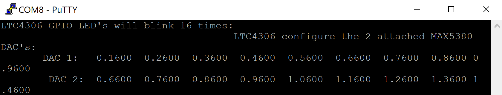
Serial output when running the basic project:
LTC4306 GPIO LED's will blink 16 times:
LTC4306 configure the 2 attached MAX5380 DAC's:
DAC 1: 0.1600  0.2600  0.3600  0.4600  0.5600  0.6600  0.7600  0.8600  0.9600
DAC 2: 0.6600  0.7600  0.8600  0.9600  1.0600  1.1600  1.2600  1.3600  1.4600
Output Capture
The image below shows the example scope shot with two MAX9611PMB’s connected to Channels 1 and 2 of the LTC4306:
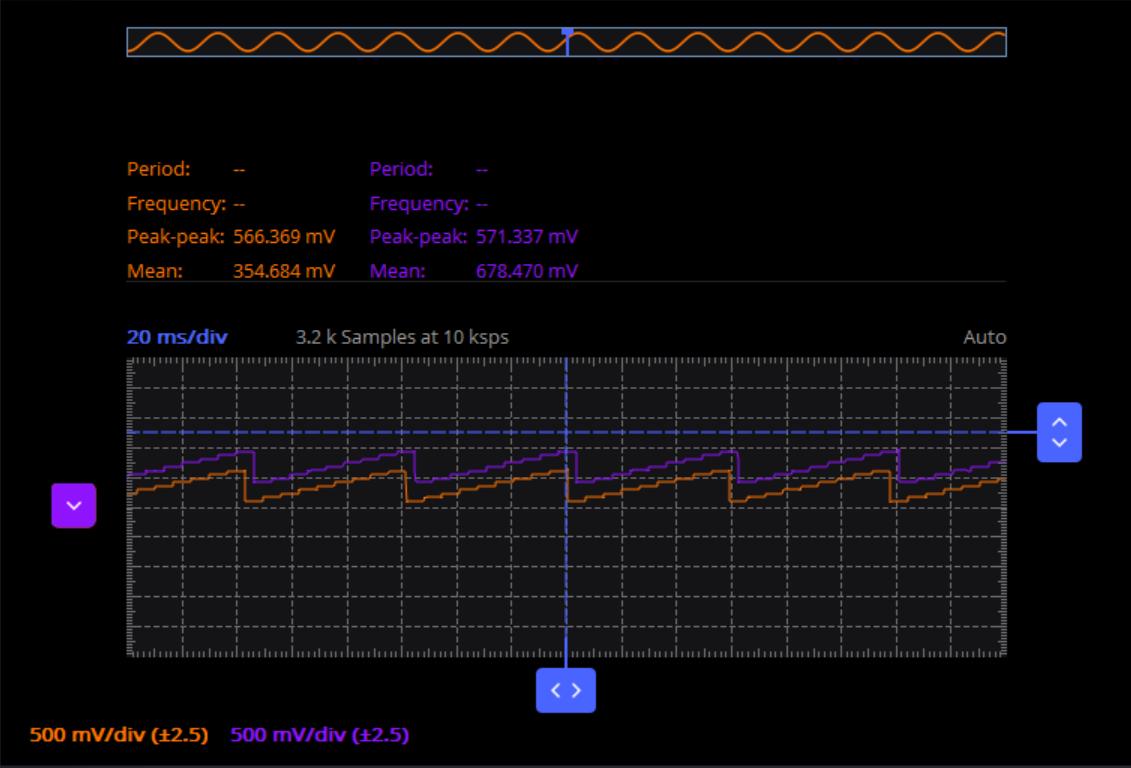
Legend |
|
|---|---|
Orange |
Channel 1 |
Purple |
Channel 2 |
Time |
20 mS/div |
Amplitude |
500 mV/div |
Hardware Output Checking
To check the hardware output when using the example code, follow below steps:
Connect the EVAL-LTC4306 to the microcontroller board by following the required connections in Hardware Setup section.
Connect the MAX9611PMB1’s to the corresponding channels (check LTC4306_NUM_DOWNSTREAM variable in basic_example.c for any changes necessary or reference) on the EVAL-LTC4306.
Build and load the example .hex file to the microcontroller board.
Reset or reconnect the microcontroller board to the computer or a power supply.
Observe the EVAL-LTC4306’s green GPIO LEDs blink for a couple of times (default is 16 times).
Connect each MAX9611PMB1 output to an oscilloscope channel.
For proper operation, a sawtooth wave offset from each other should be seen (i.e., 500 mV offset between Ch1 and Ch2).
Note
The example project runs sequentially and continuously repeats the process until power is removed.
Recommendations
People who follow the flow that is outlined, have a much better experience with things. However, like many things, documentation is never as complete as it should be. If you have any questions, feel free to ask on our EngineerZone forums, but before that, please make sure you read our documentation thoroughly.
Warning
All the products described on this page include ESD (electrostatic discharge) sensitive devices. Electrostatic charges as high as 4000V readily accumulate on the human body or test equipment and can discharge without detection. Although the boards feature ESD protection circuitry, permanent damage may occur on devices subjected to high-energy electrostatic discharges. Therefore, proper ESD precautions are recommended to avoid performance degradation or loss of functionality. This includes removing static charge on external equipment, cables, or antennas before connecting to the device.