AD7134 IIO Application
Introduction
This page gives an overview of using the ARM platforms supported (default is Mbed) firmware application with Analog Devices AD7134 Evaluation board(s) and SDP-K1/Nucleo-L552ZEQ controller board. This example code leverages the ADI developed IIO (Industrial Input Output) ecosystem to evaluate the AD7134family of devices by providing a device debug and data capture support. The code provides support to MBED and STM32 platforms.
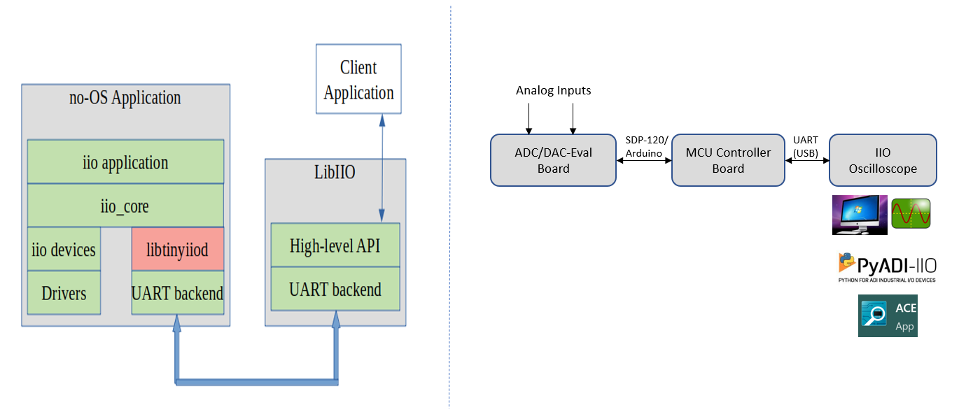
IIO oscilloscope is used as client application running on Windows-os, which is ADI developed GUI for ADC data visualization and device debug. The interface used for communicating client application with firmware application (IIO device) is UART (Note: SDP-K1 can also support high speed VirtualCOM port @1Mbps or higher speed for faster data transmission). The firmware application communicates with IIO device using ADI No-OS drivers and platform drivers low level software layers. SDP-K1 for MBED and Nucleo-L552ZEQ is used as controller board, on which IIO firmware application runs and using above software libraries, the IIO firmware communicates with IIO device.
Note
This code has been developed and tested for mbed platform on the SDP-K1 and for STM32 platform on the Nucleo-L552ZEQ Controller Board. However, same code can be used without or with little modifications on any Mbed or STM32 enabled board which has Arduino/Arduino+Zio Header Support on it, such as STM32-Discovery, STM32-Nucleo, etc.
Useful links
Hardware Connections
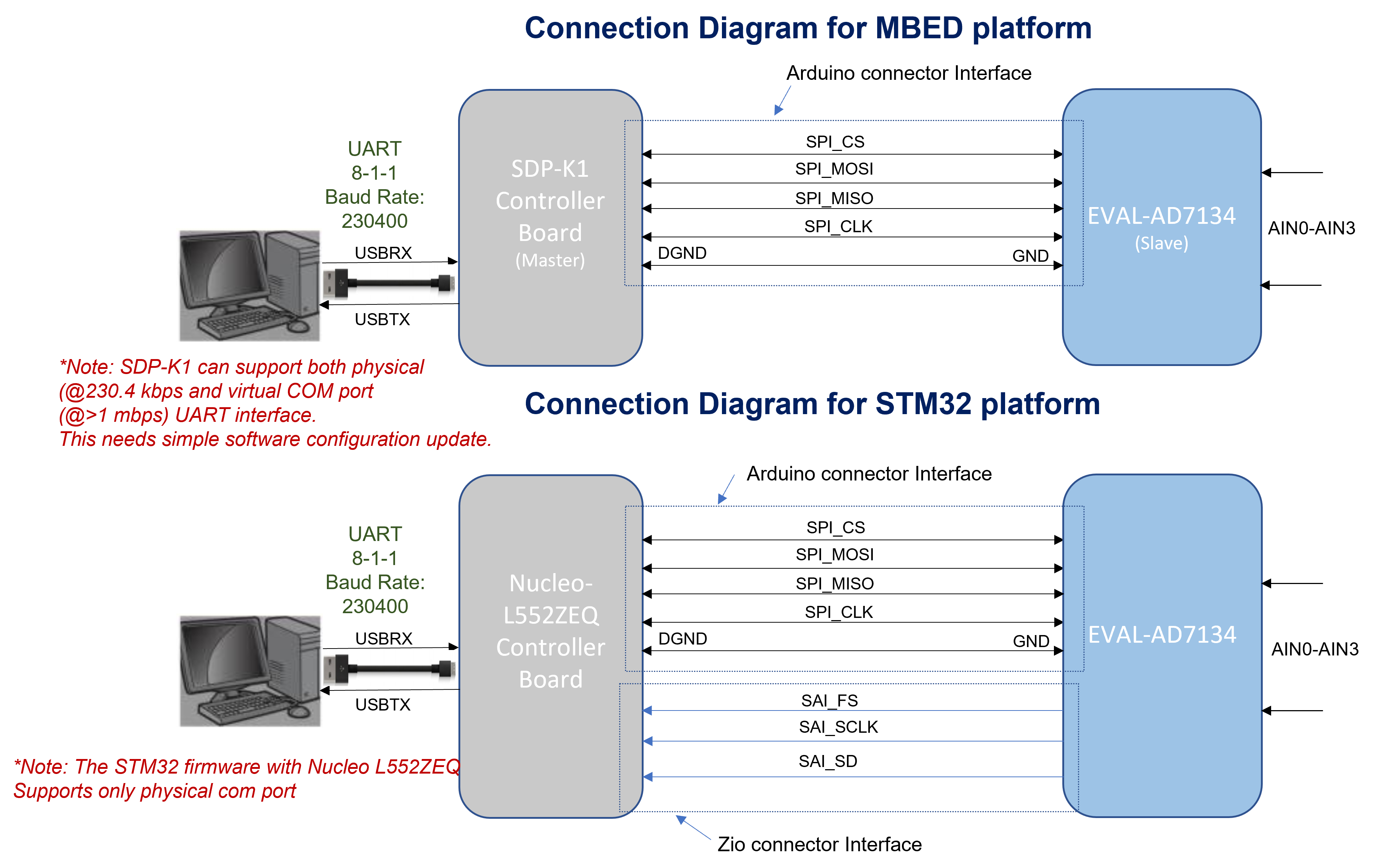
SDP-K1 for mbed platform:
Connect the VIO_ADJUST jumper on the SDP-K1 board to 3.3V position to drive SDP-K1 GPIOs at 3.3V
Nucleo L552ZEQ for STM32 platform:
The Nucleo L552ZEQ board has been used to develop and test the STM32 firmware. Please refer to the board user guide Nucleo-L552ZEQ User Manual.
EVAL-AD7134:
Connect a 9V power supply to the appropriate header on the Eval Board. The device mode of operation can be set to either ‘MASTER’ Or ‘SLAVE’ by changing P10 jumper position. If P10 is open, the mode of operation is master (which is a default mode on EVB and as well in the firmware). If P10 is shorted, the mode of operation is slave. Make sure to change the mode in both software (app_config.h file) and hardware and power-cycle the AD7134 EVB to reflect new mode.
Please contact product application engineer for more details on the jumper connections and reference manual.
Please refer to the respective board user guide on the product page of the chosen device.
UART Connections
For data transmission to IIO client, VirtualCOM or UART serial communication is used. SDP-K1 by default uses the VCOM serial interface for higher speed data transmission.
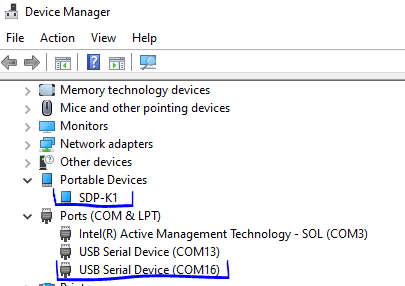
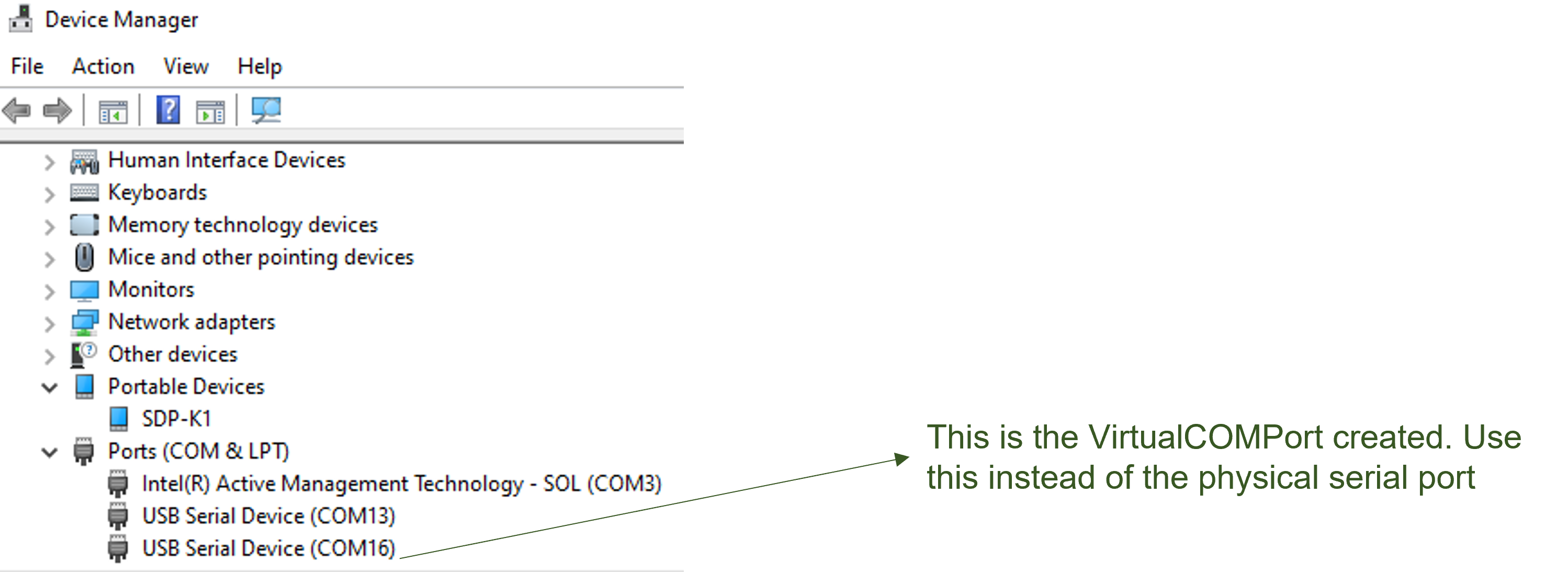
SDP-K1 is powered through USB connections from the computer. SDP-K1 acts as a Serial device when connected to PC, which creates a COM Port to connect to IIO Oscilloscope GUI running on windows-os. The COM port assigned to a device can be seen through the device manager for windows-based OS.
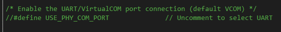
SDP-K1 can support high speed VirtualCOM port USB interface, so by default VCOM
is configured as default interface in the firmware. The interface can be set to
UART by defining macro USE_PHY_COM_PORT in the app_config.h file.
Warning
Actual COM port number for your device may not be the same as shown above. Therefore, always check your SDP-K1 serial COM port number before connecting to IIO client.
MBED and STM32 Firmware
This section briefs on the usage of MBED and STM32 firmware. This also explains the steps to compile and build the application using mbed and make based build.
Download
Source code is hosted here:
Build Guide for Precision Converters MBED firmware (Use below link):
Build Guide for Precision Converters STM32 firmware (Use below link):
Libiio: IIO Library
The libiio library provides an abstracted interface to communicate between the IIO device and the IIO client application (IIO Oscilloscope) without worrying about low level hardware details. Download and install the libiio Windows installer on your computer.
IIO Oscilloscope (Client)
The IIO Oscilloscope is a GUI based IIO client application for data visualization and device configuration/debugging. It provides visualization of data from IIO devices (ADCs/DACs) transmitted via Serial/Ethernet/USB connections through the libiio abstraction layer. Download and install the IIO Oscilloscope Windows installer on your computer.
Download
IIO Oscilloscope installer for Windows (Use below link):
Evaluating AD7134 Using IIO Ecosystem
Note
Ensure that the hardware connection has been made properly between the Controller Board (SDP-K1) and the ADC Eval board. Also ensure all software (IIO firmware, Libiio windows installer and IIO Oscilloscope windows installer) are downloaded and installed on your computer before trying to communicate with the device.
Running IIO Oscilloscope (Client)
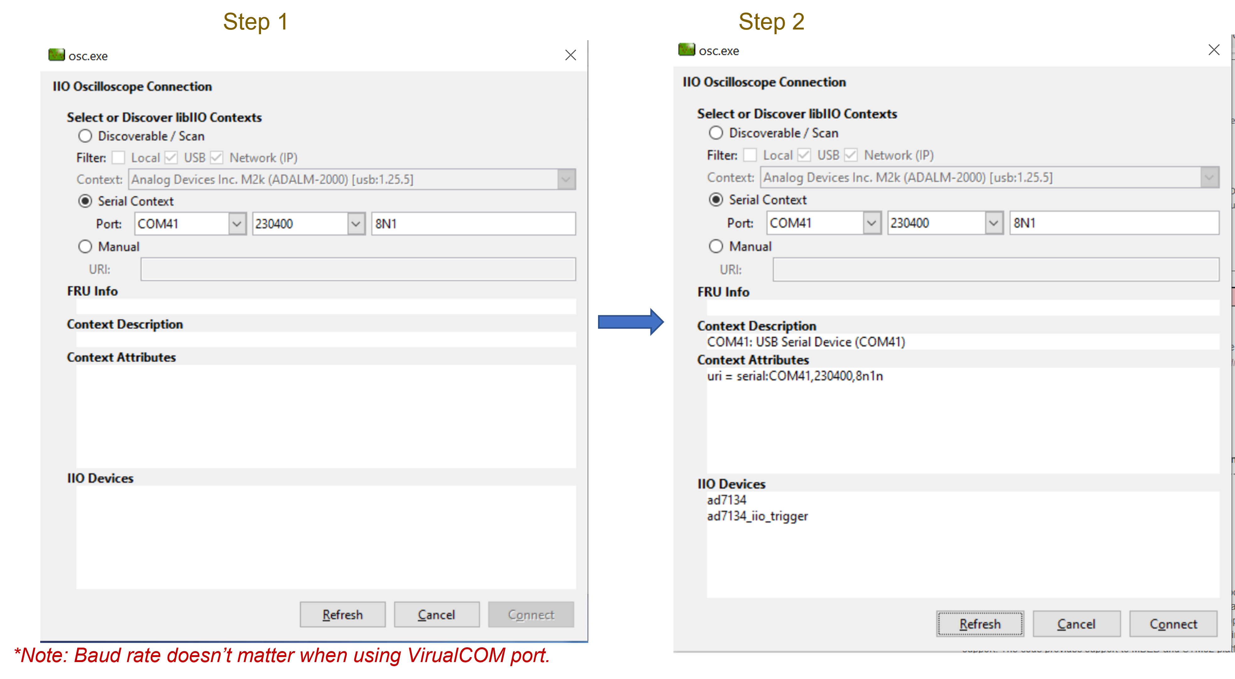
Open the IIO Oscilloscope application from start menu and configure the serial (UART) settings as shown below. Click on refresh button and AD7134 device should pop-up in IIO devices list.
Click ‘Connect’ and it should by default open the data ‘Capture’ window. You can drag aside or close this window to see the main ‘Debug and DMM’ tab window.
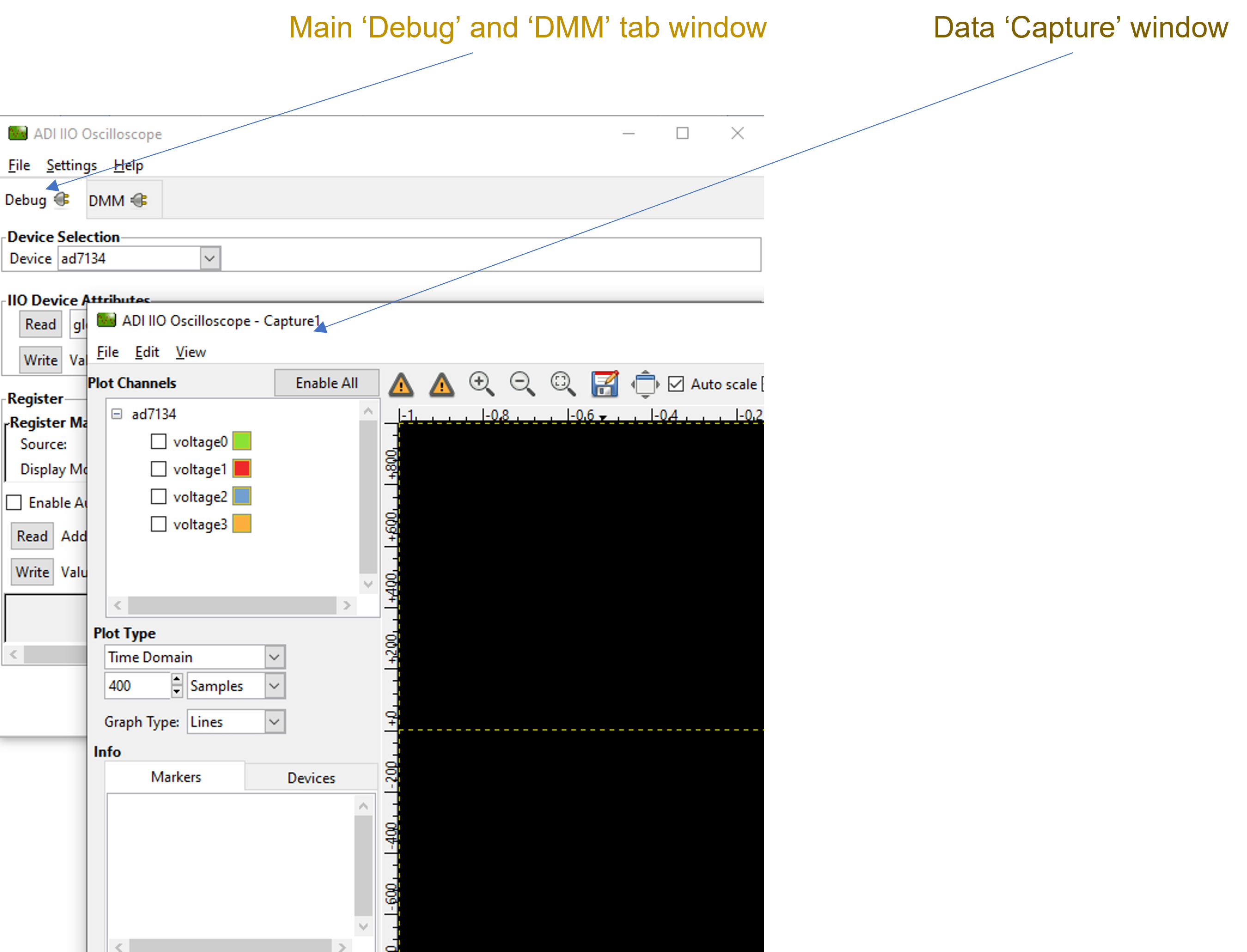
Select the device from ‘Device’ pop-up list on ‘Debug’ tab window. This will make available all device specific and channel specific attributes.
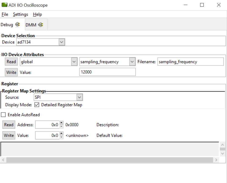
Configure/Access Device Attributes (Parameters)
The IIO Oscilloscope allows user to access and configure different device parameters, called as ‘Device Attributes“. There are 2 types of attributes:
Device Attributes (Global): Access/Configure common device parameters.
Channel Attributes (Specific to channels): Access/Configure channel specific device parameters.
How to read and write attribute:
To ‘Read’ an attribute, simply select the attribute from a list or press ‘Read’ button on left side.
To ‘Write’ an attribute, select attribute value in the ‘value field’ and press ‘Write’ button.
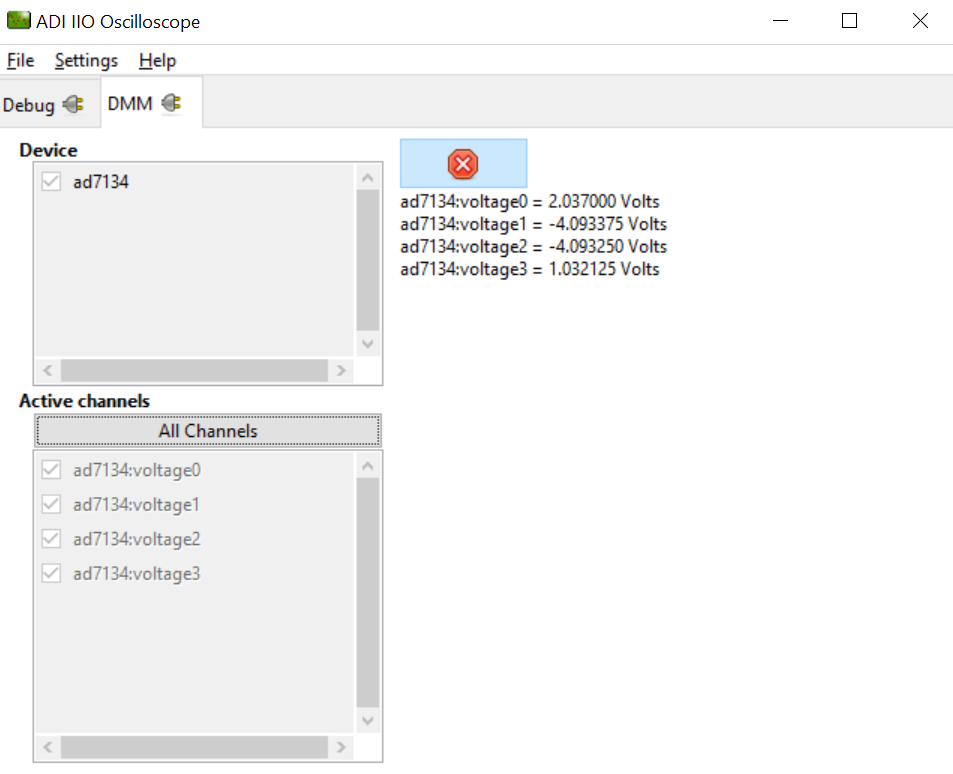
Using DMM Tab to Read DC Voltage on Input Channels
DMM tab can be used read the instantaneous voltage applied on analog input channels. Simply select the device and channels to read and press start button.
*Note: The voltage is just instantaneous, so it is not possible to get RMS AC voltage or averaged DC voltage. Also, when using DMM tab, do not access/use the Data Capture or Debug tab as this could impact data capturing. Both DMM scan and data capture uses different methods of conversion. The DMM data is read using single conversion, while data capture uses continuous conversion mode of operation.
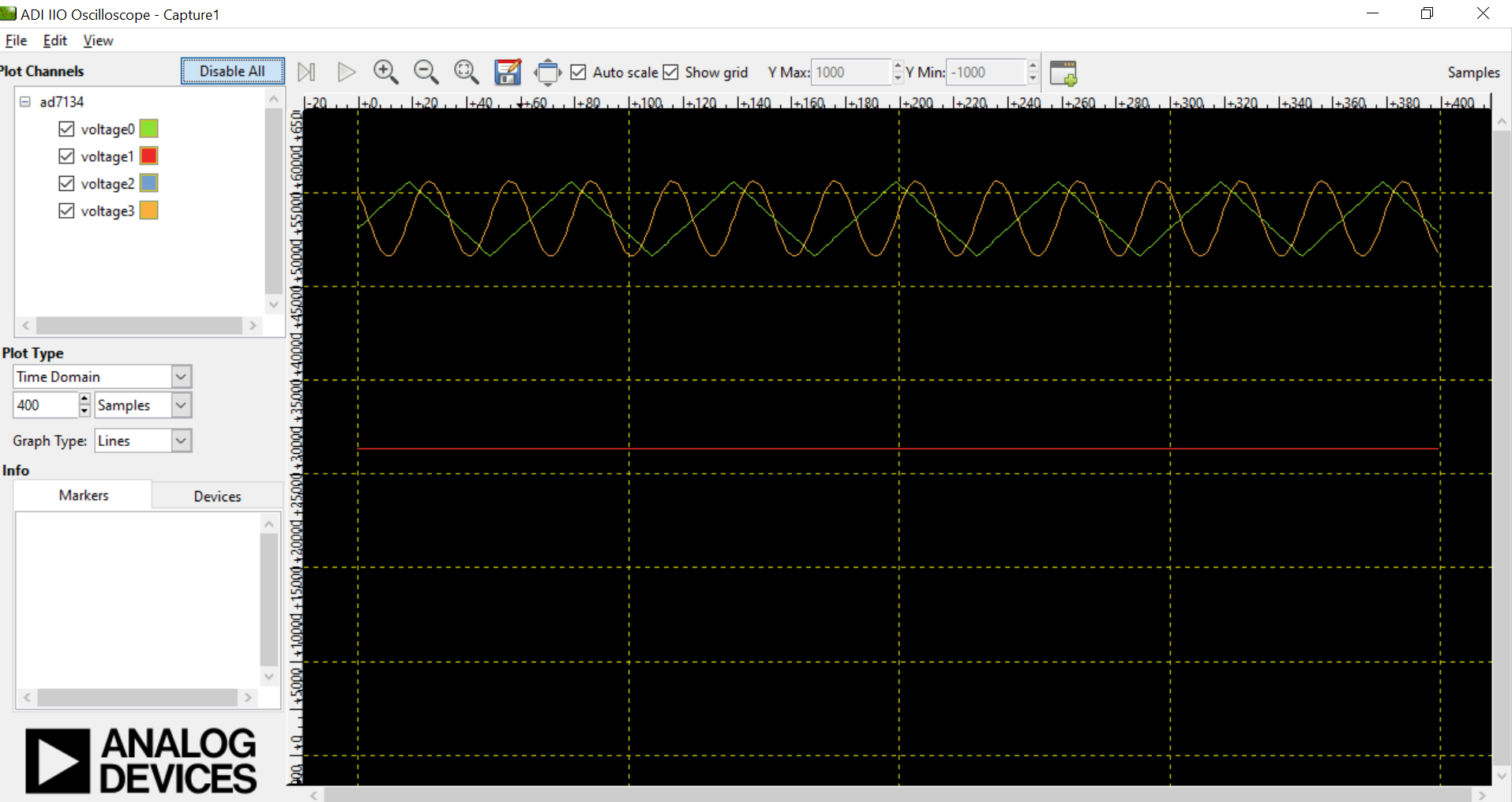
Data Capture from IIO Device
To capture the data from AD7134 IIO device, simply select the device and channels to read/capture data. The data is plotted as “ADC Raw Value” Vs “Number of Samples” and is just used for Visualization. The data is read as is from device without any processing. If user wants to process the data, it must be done externally by capturing data from the Serial link on controller board.
Warning
The DMM or Debug tab should not be accessed when capturing data as this would impact data capturing. Both DMM scan and data capture uses different methods of conversion. The DMM data is read using single conversion, while data capture uses continuous conversion mode of operation. More info here: Using DMM Tab to Read DC Voltage on Input Channels
Time Domain Plot
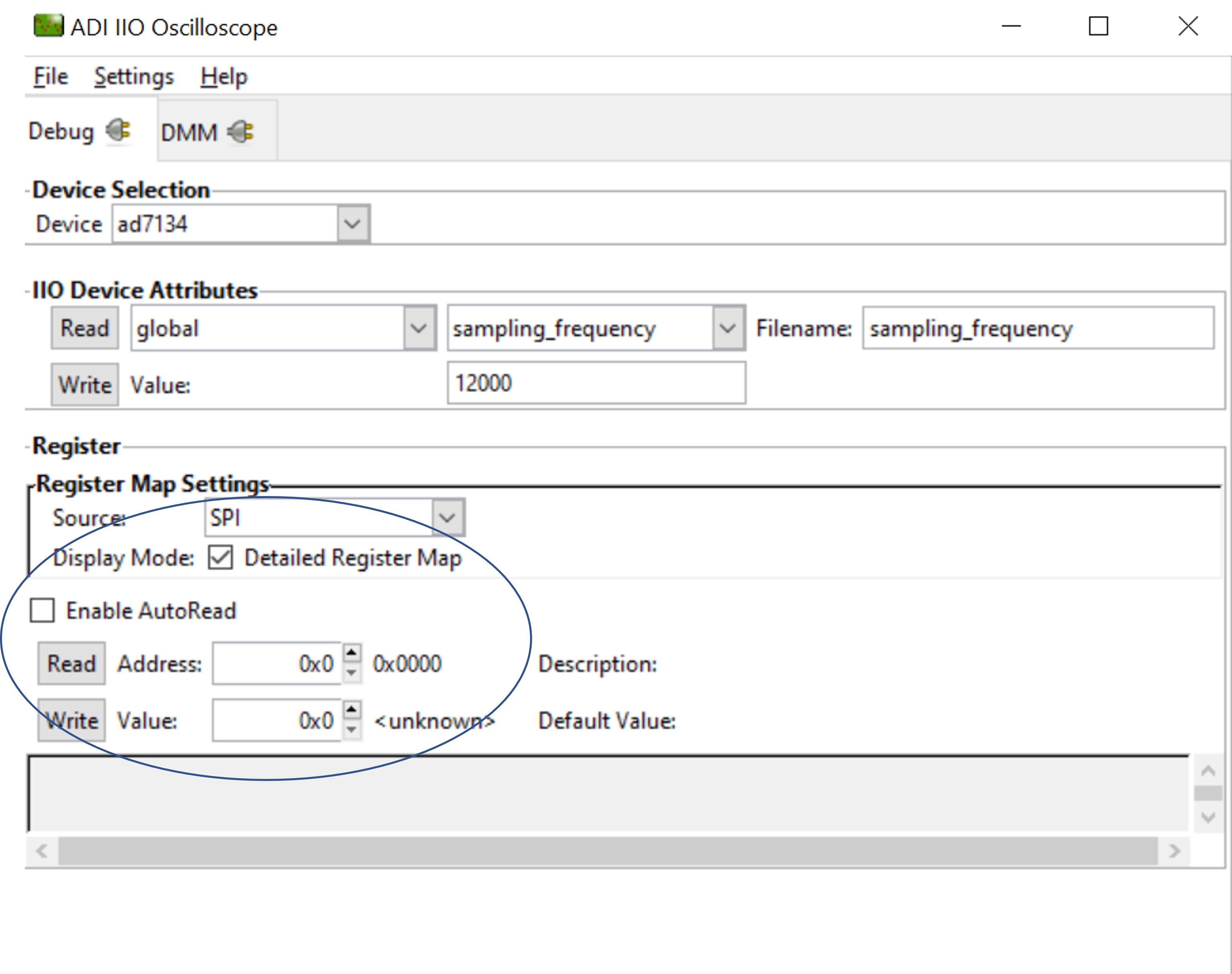
Access Register map of IIO Device
This tab is used to access the device registers in byte mode.
Python Environment and Scripts
Data capture can be achieved with clients other than the IIO Oscilloscope as well. A possible option using ADI’s pyadi-iio library in python has been demonstrated in the forthcoming sections. The ad7134_data_capture.py is capable of achieving the same.
Setting-up Python Environment
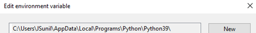
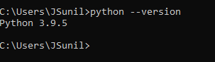
Please install python into your local machine. The python scripts are developed and executed using python 3.9.0 version, so recommend using version 3.9.0 or beyond. Download python
Once python is installed, make sure the environment path (on windows machine) is set properly. You can verify if python is installed properly by typing “python –version” command on command line tool such as gitbash, command prompt, power shell, etc.
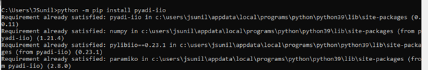
Install the “pyadi-iio” python package by executing command
python -m pip
install pyadi-iio
. Detailed guide on installing it is available in Python Interfaces for ADI Hardware
Note
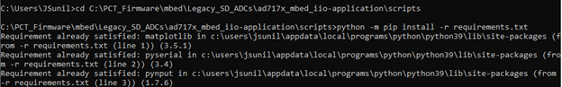
Make sure to install additional support packages by running requirements.txt
file using command python -m pip install -r requirements.txt from
scripts/ directory.
Modifying/running Python Scripts
All python scripts specific to the IIO firmware are stored into
scriptsfolder present in the project directory. So, any script must be executed from this folder.
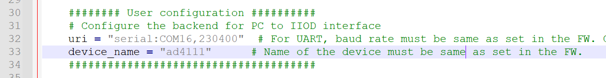
Update the
uriinterface in script according to COM port assigned to your device (sdp-k1). Default COM port is set to COM16 in all scripts.
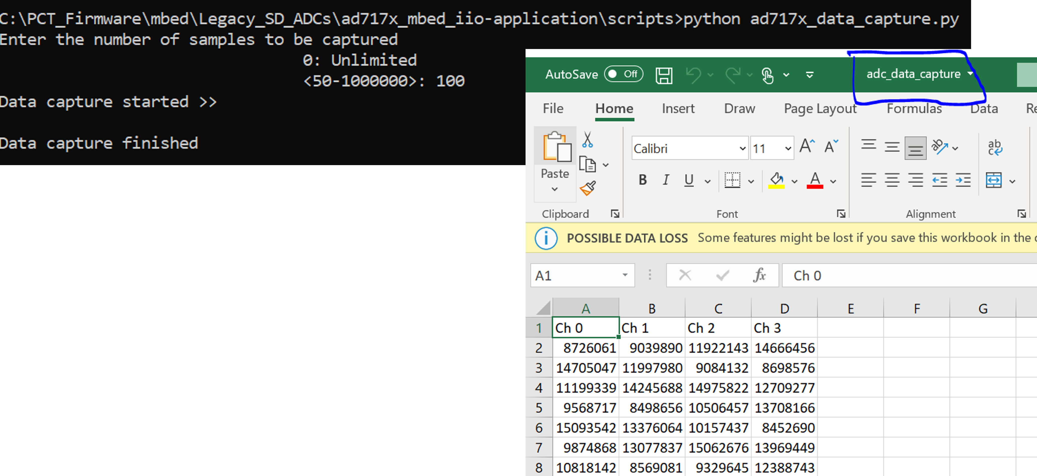
Output Obtained from the Python Script
While executing the adxxxx_data_capture.py, the command prompt requests for the number of samples to be entered by the user.
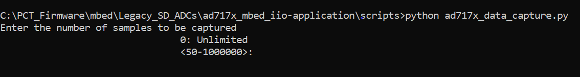
On entering the number of samples n, on successful completion of capturing n samples, the data points are stored in a csv as adc_data_capture.csv in the folder where the script is present.
AD7134 Firmware Structure
app_config.h
This file can be used to:
Select the platform in which the firmware needs to be used. MBED and STM32 platforms are supported now. Select the active platform by modifying the ‘#define ACTIVE_PLATFORM’ to ‘MBED_PLATFORM’ or ‘STM32_PLATFORM’ depending on the requirement.
Select the DATA_CAPTURE_MODE to set the data capturing to CONTINUOUS_DATA_CAPTURE or BURST_DATA_CAPTURE
Switch between two modes- SPI_MODE and TDM_MODE which can be chosen accordingly via the INTERFACE_MODE macro.
Switch between CONTROLLER_MODE and TARGET_MODE using the AD7134_ASRC_MODE macro.
Important
Note that the maximum Output Data Rate of the device can be leveraged by selecting the TDM_MODE in the STM32 platform. There is a limit in the maximum achievable ODR while in SPI_MODE.
ad7134_user_config.c
This file defines the user configurations for the AD7134, such as SPI parameters (frequency, mode, etc) and other init parameters used by No-OS drivers to initialize AD7134 device (e.g. required GPIOs, software/hardware mode, etc). These are the parameters loaded into device when device is powered-up or power-cycled.
ad7134_iio.c
This file defines getter/setter functions for all the device and channel specific attributes (related to AD7134 devices) to read/write the device parameters. The majority of device specific functionality is present in this module.
ad7134_support.c
This file contains all the support functions utilized in the firmware
app_config_mbed.c
This file contains all the extra parameters specific to mbed platform
app_config_stm32.c
This file contains all the extra parameters specific to STM32 platform. There might be a need to change certain parameters if any board other than the Nucleo-L552ZEQ is chosen.
No-OS Drivers for AD7134
The no-os drivers provide the high level abstracted layer for digital interface of AD7134 devices. The complete digital interface (to access memory map and perform data read) is done in integration with platform drivers.
The functionality related with no-os drivers is covered in below 2 files:
ad7134.c
ad7134.h
Tip
It is hoped that the most common functions of the AD7134 family are coded, but it’s likely that some special functionality is not implemented. Feel free to consult Analog Devices Engineer-Zone for feature requests, feedback, bug-reports etc.