EVAL-ADE9000SHIELDZ
EVAL-ADE9000SHIELDZ Sensor for Electric Metering
Overview
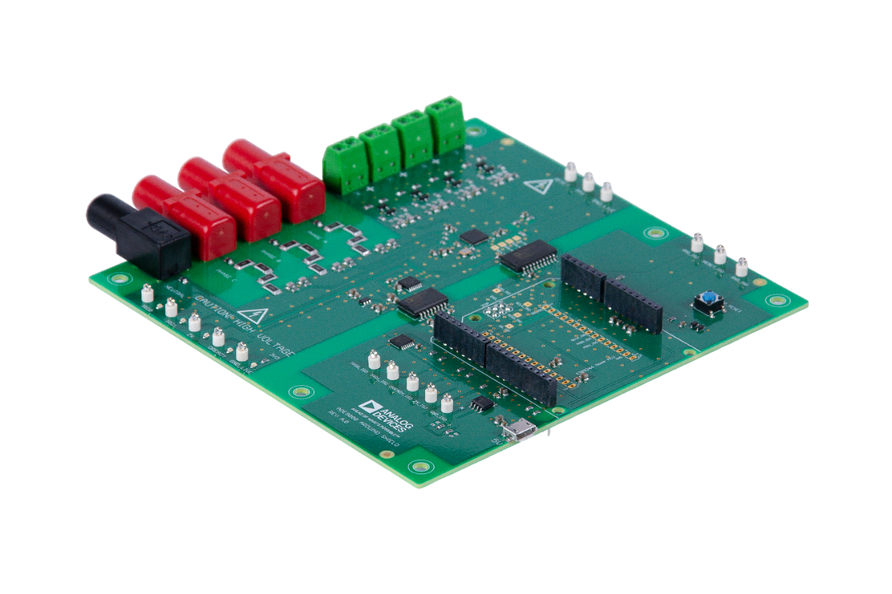
The EV-ADE9000SHIELDZ is an Arduino shield compatible with Arduino Zero. The shield can be directly interfaced with current transformers and voltage leads. It enables quick evaluation and prototyping of energy and power quality measurement systems with the ADE9000. Arduino library and application examples are provided to simplify implementation of larger systems.
Features
Arduino-compatible energy and power quality measurement shield with ADE9000 multiphase energy and power quality monitoring IC
3P4W, 3P3W, or 3-wire single phase measurements
Direct interface with current output current transformers
Up to 240V rms nominal line neutral voltage measurement
Arduino software library
Calibration and example application sketches
Application
Tip
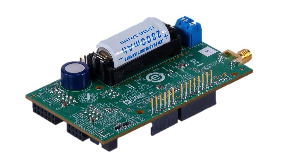
The EV-ADE9000SHIELDZ can be used with the MAX32670-SX-ARDZ Base Board, which is a long-range wireless radio development platform based on MAX32670 ultralow power Arm Cortex-M4 microcontroller and SX1261 RF transceiver.
Using these platforms together enables users to design solutions based on low-power, long range proprietary radio communication technique that is suitable for customized heat/flow meters.
To learn more about the Long Range Wireless Radio solution developed by Analog Devices, visit the AD-MAX32SXWISE-SL Long Range Wireless Radio Development Kit User Guide
System Setup
PHASE 1: Hardware Setup
Note that this setup only applies for MAX32670-SX-ARDZ Base Board. Users may use a different base board or microcontroller, however the firmware built for this demo application cannot be used as this is specifically designed for the MAX32670-SX-ARDZ.
Equipment Needed
One (1) MAX32670-SX-ARDZ Base Board
One (1) EV-ADE9000SHIELDZ Sensor Node
One (1) MAX32625PICO Rapid Development Platform with 10-pin ribbon cable
with firmware image: MAX32625PICO Firmware Image for MAX32670
One (1) Micro USB to USB cable
Host PC (Windows 10 or later)
One (1) CR123A Battery or any equivalent external DC power supply (+3V to +4.7V). Note that this is not included in the kit
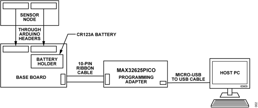
Insert one CR123A battery (3V to 4.7V) into the battery holder (BT1 connector) of the MAX32670-SX-ARDZ Base Board. Make sure to check for the battery polarity in the BT1 connector, refer to the figure below. The DS3 LED will light up indicating that you have inserted the battery correctly and that power is provided in the base board.
Connect the EV-ADE9000SHIELDZ Sensor Node to the MAX32670-SX-ARDZ Base Board by aligning the corresponding Arduino headers on each board.
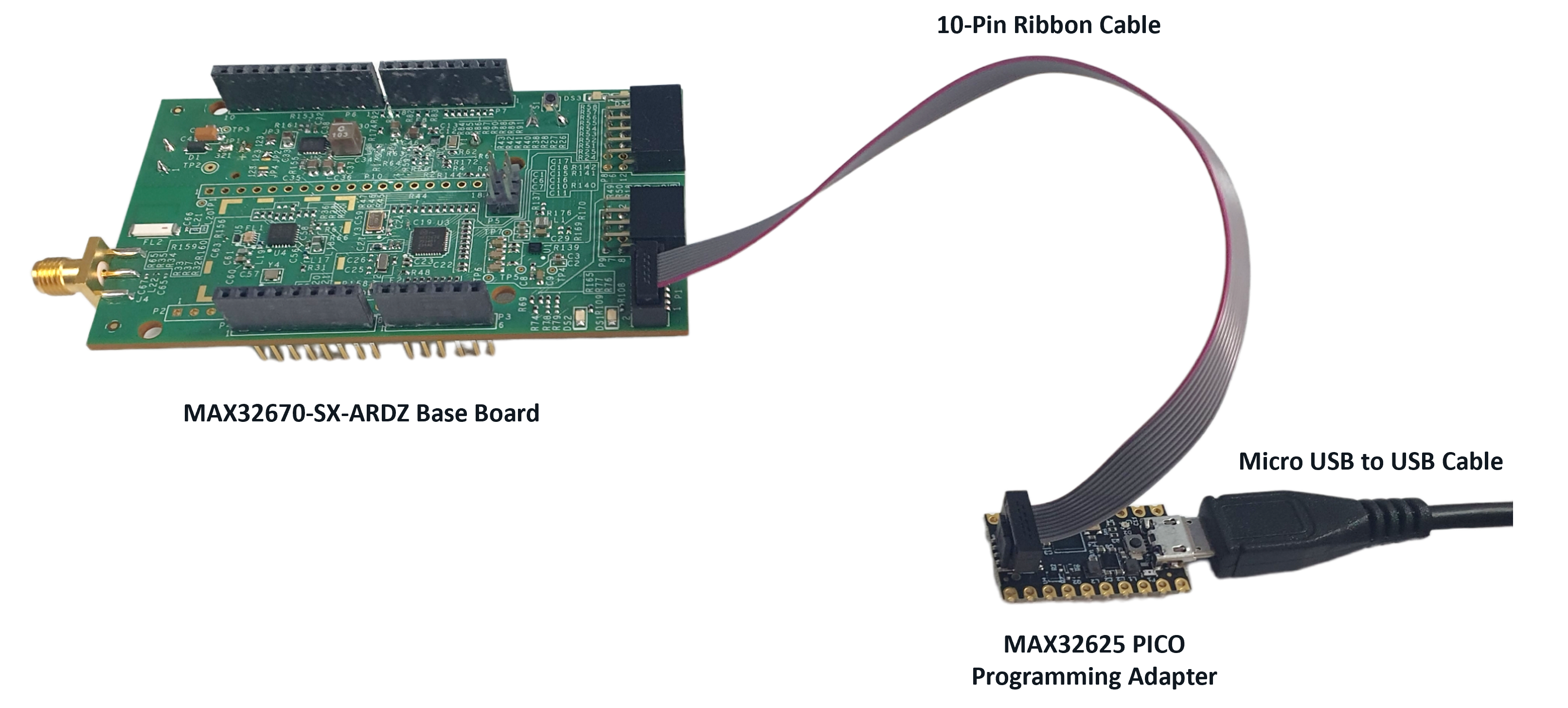
Connect the MAX32625PICO programming adapter to the MAX32670-SX-ARDZ Base Board through the 10-pin ribbon cable.
Make sure that the MAX32625PICO programming adapter has been flashed with the correct image before connecting it to the MAX32670-SX-ARDZ Base Board. If you do not know how to load the image, click on the instructions below:
Download the firmware image: MAX32625PICO Firmware Image for MAX32670
Do not connect the MAX32625PICO to the MAX32670-SX-ARDZ Base Board yet.
Connect the MAX32625PICO to the Host PC using the micro-USB to USB cable.
Press the button on the MAX32625PICO. (Do not release the button until the MAINTENANCE drive is mounted).
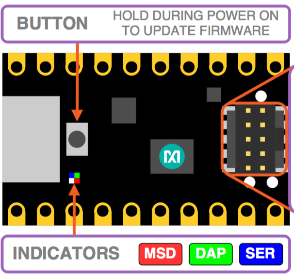
Release the button once the MAINTENANCE drive is mounted.
Drag and drop (to the MAINTENANCE drive) the firmware image.
After a few seconds, the MAINTENANCE drive will disappear and be replaced by a drive named DAPLINK. This indicates that the process is complete, and the MAX32625PICO can now be used to flash the firmware of the MAX32670-SX-ARDZ Base Board.
Connect the MAX32625PICO programming adapter to the Host PC using the micro-USB to USB cable.
Note
Once you have completed this setup, proceed to PHASE 2 found in ADI Long Range Wireless Radio Software User Guide.
Resources
Design and Integration Files
Warning
All the products described on this page include ESD (electrostatic discharge) sensitive devices. Electrostatic charges as high as 4000V readily accumulate on the human body or test equipment and can discharge without detection. Although the boards feature ESD protection circuitry, permanent damage may occur on devices subjected to high-energy electrostatic discharges. Therefore, proper ESD precautions are recommended to avoid performance degradation or loss of functionality. This includes removing static charge on external equipment, cables, or antennas before connecting to the device.
Help and support
Please go to Help and Support page.