EVAL-CN0535-FMCZ
High Performance, Alias Free Measurement Platform for Flexible Data Acquisition System
Overview
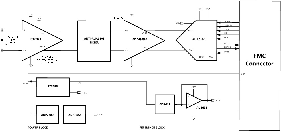
The EVAL-CN0535-FMCZ is a data acquisition (DAQ) system that measures real world physical phenomenon such as temperature, force, acceleration, or vibration, converting measurements into digital values for data processing, storage, or transmission to a remote location. A typical DAQ system is comprised of a sensor, analog filtering and signal conditioning circuitry, an analog-to-digital converter (ADC), and digital controller. Components for a DAQ solution are selected on a per application basis. Some DAQ systems are designed to minimize the overall system DC error from sensor, with fast settling filters for control-loop or multiplexed applications. Others are designed to provide superior AC performance, with low distortion and flat frequency response.
Features
Alias free Measurement System
Optimized for AC and DC Performance
Wide Analog Input (+/-12V)
FMC Compatible Form Factor
Applications
Control loop or multiplexed applications
AC and DC application
Getting Started
The CN0535 can be used for a wide range of applications, and the following demos are meant to show examples of the flexibility of the board. To get started with setup, configuration, and example use cases, please proceed to the provided demo page.
Hardware Setup
Equipment Required
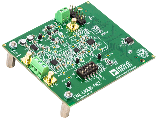
CN0535 Circuit Evaluation Board (EVAL-CN0535-FMCZ)
System Demonstration Platform Board (EVAL-SDP-CH1Z)
AP2700 Signal Source or Equivalent
Hardware Connection
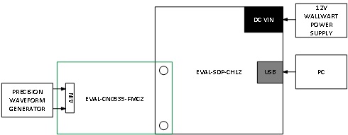
To begin using the evaluation board, take the following steps:
Ensure the EVAL-SDP-CH1Z system demonstration platform board is disconnected from the PC. Install the AD7768-1 Evaluation Board Software. Restart the PC after the software installation is complete.
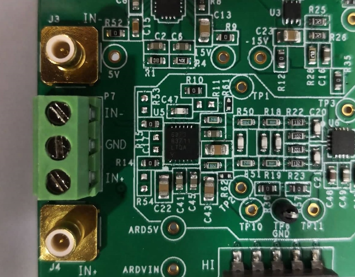
Connect the EVAL-SDP-CH1Z system demonstration platform board to the EVAL-CN0535-FMCZ reference design board. The J4 connector of the EVAL-SDP-CH1Z system demonstration platform board connects to the receiving socket P1 on the EVAL-CN0535-FMCZ.
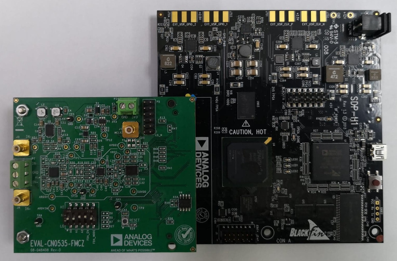
Ensure the evaluation boards are securely connected together by tightening the mounting screws.
Connect the 12 V DC power supply to the EVAL-SDP-CH1Z system demonstration platform board, then connect the provided USB cable from the board to the PC. If prompted, allow the operating system to automatically search for and install the EVAL-SDP-CH1Z drivers.
Launch the AD7768-1 evaluation board software from the Analog Devices folder in the Programs menu.
Connect the differential input source to the SMB connectors (J3 and J4). P7 can also be used for a wired source.
In the AD7768-1 evaluation software, click the Sample button.
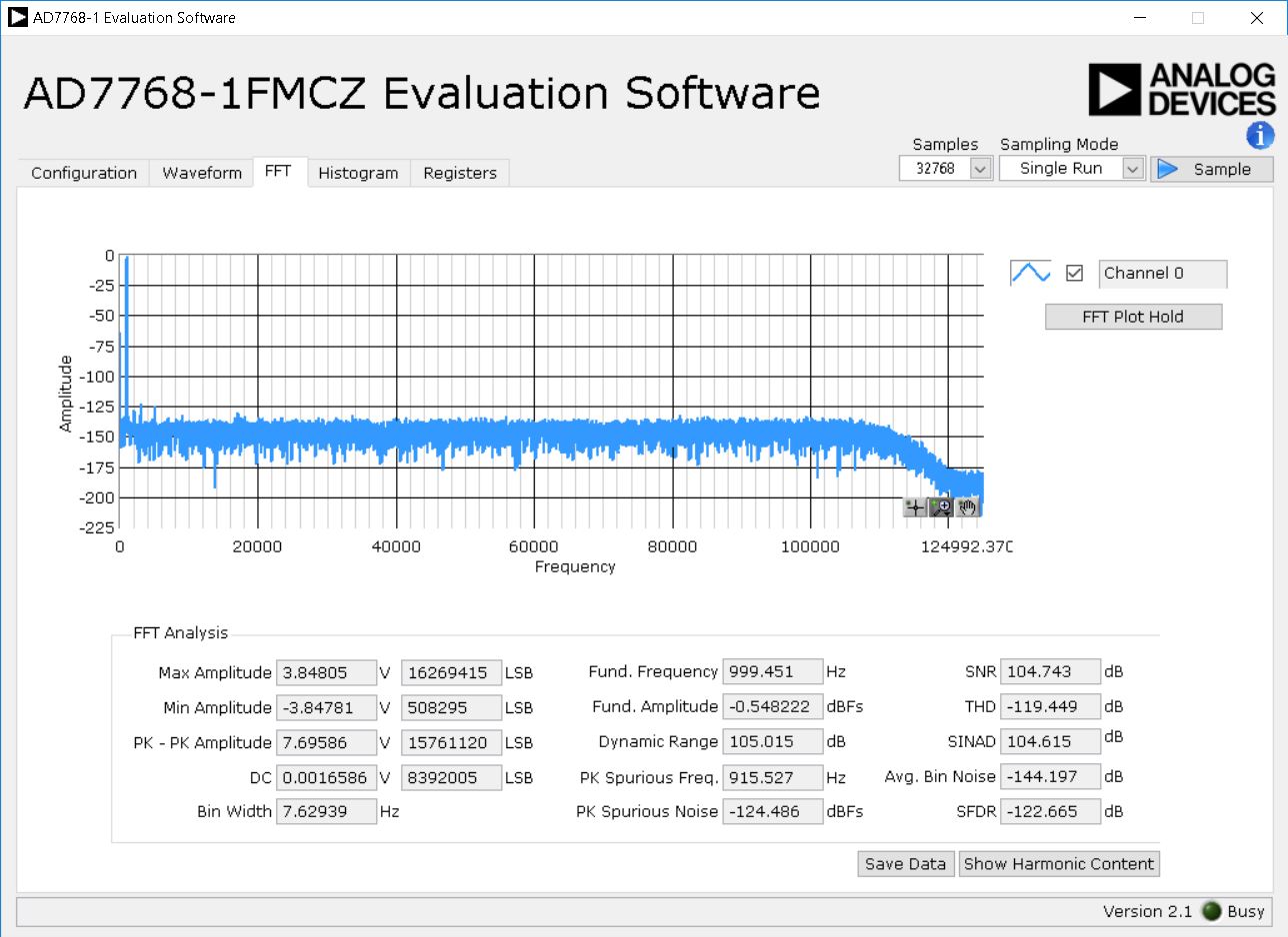
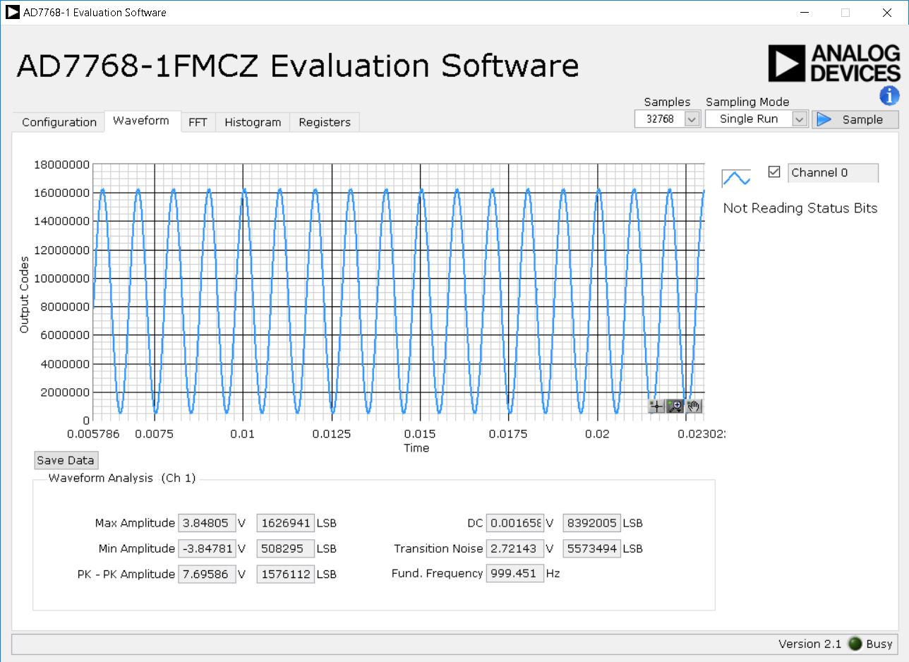
Below are the measured values for a 5.9 Vp-p sine input from an AP2700 signal source.
FFT Tab
Waveform Tab
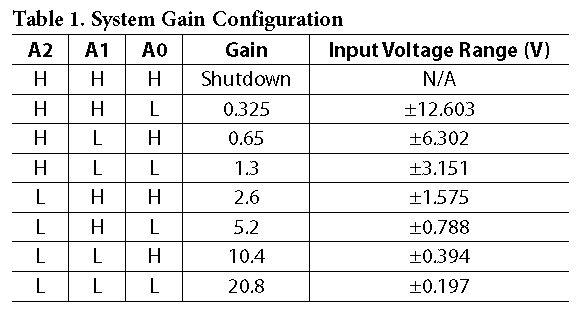
System Gain Configuration
Select the gain by configuring the switch (S2) on the EVAL-CN0535-FMCZ board. Table 1 shows the system gain and the corresponding input voltage ranges.
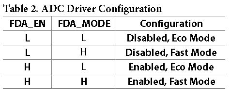
ADC Driver (ADA4945-1) Configuration
Select the ADC driver mode by configuring the switch (S2) on the EVAL-CN0535-FMCZ board.
Software GUI Setup
GUI Main Window

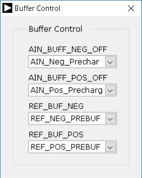
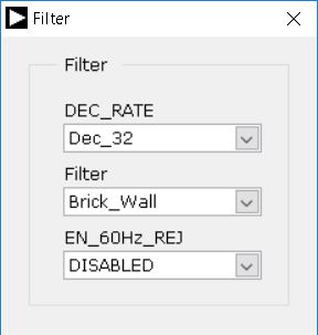
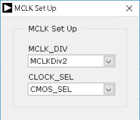
The main window of the GUI allows the user to configure the following settings on the ADC
Buffer Control: This allows the user to configure the internal ADC input and reference buffers
Digital Filter Control: This allows the user to select the digital filter setting of the ADC
MCLK DIV: This allows the user to configure the MCLK divider setting on the ADC
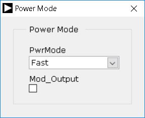
Power Mode: This sets the power mode setting on the ADC. the user can select from Fast, Median and Low power mode setting.
Schematic, PCB Layout, Bill of Materials
Download
EVAL-CN0535-FMCZ Design & Integration Files
Schematics
PCB Layout
Bill of Materials
Allegro Project
Additional Information and Useful Links
Software Projects and Platforms
Registration
Tip
Receive software update notifications, documentation updates, view the latest videos, and more when you register your hardware. Register to receive all these great benefits and more!
Warning
All the products described on this page include ESD (electrostatic discharge) sensitive devices. Electrostatic charges as high as 4000V readily accumulate on the human body or test equipment and can discharge without detection. Although the boards feature ESD protection circuitry, permanent damage may occur on devices subjected to high-energy electrostatic discharges. Therefore, proper ESD precautions are recommended to avoid performance degradation or loss of functionality. This includes removing static charge on external equipment, cables, or antennas before connecting to the device.
Help and support
Please go to Help and Support page.