MAX11205PMB1
MAX11205PMB1 Peripheral Module
Overview
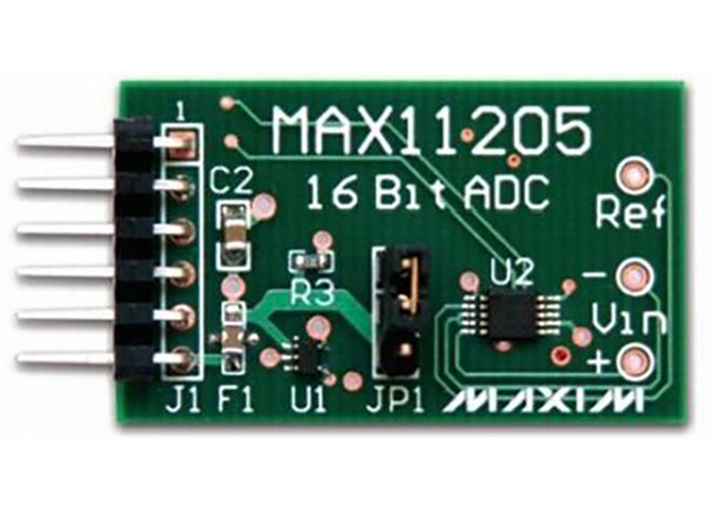
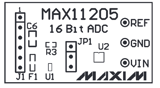
The MAX11205PMB1 peripheral module provides the necessary hardware to interface the MAX11205 16-bit ADC to any system that utilizes Pmod™-compatible expansion ports configurable for GPIO interface. The IC is an ultra-low-power (< 300µA max active current), high-resolution, serial-output ADC. This device provides the highest resolution per unit power in the industry and is optimized for applications that require very high dynamic range with low power, such as sensors on a 4mA to 20mA industrial control loop. The voltage reference for the IC is supplied by a MAX6037 (2.5V) that is also on the module. The filtered power-supply voltage from the host can be optionally passed (jumper selectable) through a MAX8510 ultra-low-noise LDO, allowing empirical evaluation of performance with different power sources.
Refer to the MAX11205 data sheet for detailed information regarding operation of the IC.
Features
16-Bit Full-Scale Resolution
Internal System Clock
2-Wire Serial Interface
On-Board Voltage Reference (MAX6037, 2.5V Version)
Filtered Power Supply with Optional (Jumper-Selectable) Ultra-Low Noise LDO
6-Pin Pmod-Compatible Connector (GPIO)
Example Software Written in C for Portability
RoHS Compliant
Proven PCB Layout
Fully Assembled and Tested
Applications
Battery Applications
Portable Instrumentation
Temperature/Pressure Measurement
Weight Scales
Evaluating the MAX11205
Supported Evaluation Boards
Hardware Specifications
Power Supply Requirements
The MAX11205PMB1 board has to be supplied with a voltage between 1.7V and +3.6V. If using directly with a PMOD connector, the host board should be capable of providing the 3.3V supply.
Digital Interface (PMOD)
The PMOD interface is a series of standardized digital interfaces for various digital communication protocols such as SPI, I2C, and UART. These interface types were standardized by Digilent, which is now a division of National Instruments. Complete details on the PMOD specification can be found here.
The specific interface used for the MAX11205PMB1 boards is SPI.
P1 Pin Number |
Pin Function |
Mnemonic |
|---|---|---|
Pin 1 |
N.C. |
CS |
Pin 2 |
N.C. |
MOSI |
Pin 3 |
Main In Subordinate Out |
MISO |
Pin 4 |
Serial Clock |
SCLK |
Pin 5 |
Digital Ground |
DGND |
Pin 6 |
Digital Power |
VDD |
ADI No-OS
The goal of ADI Microcontroller No-OS is to be able to provide reference projects for lower end processors, which can’t run Linux, or aren’t running a specific operating system, to help those customers using microcontrollers with ADI parts. ADI no-OS offers generic drivers which can be used as a base for any microcontroller platform and also example projects which are using these drivers on various microcontroller platforms.
For more information about ADI No-OS and supported microcontroller platforms see: no-OS
MAX11205 Driver
Information about the MAX11205 driver can be found here: MAX11205 driver
No-OS Supported Platforms
Maxim Platform
Required Hardware
Required Connections
The MAX32655FTHR does not have a PMOD interface, but you may use Dupont male-female cables to make the required connections. The following table shows the connection between MAX11205PMB1 and MAX32655FTHR in this project example.
P1 MAX11205PMB1 Pin Number |
MAX32655 Pin Number |
Function |
Mnemonic |
|---|---|---|---|
Pin 1 |
N.C. |
||
Pin 2 |
N.C. |
||
Pin 3 |
MISO |
Main In Subordinate Out |
MISO |
Pin 4 |
SCLK |
Serial Clock |
SCLK |
Pin 5 |
GND |
Digital Ground |
DGND |
Pin 6 |
POWER 3.3V |
Digital Power |
VDD |
Pin 3 |
P1_6 |
Data Ready |
DRDY |
No-OS Build Setup
Learn about no-OS Build Guide.
Example Project Execution
Basic Project
The basic project contains the generic HAL initialization of the used platform, together with the SPI, IRQ, and UART driver configuration and initialization.
The SPI driver is used to communicate with the MAX11205PMB1 device, the IRQ driver is used to sample data when the conversion finishes (signaled by MISO line) and the UART driver is used to display on the host machine the measured data.
In order to build the example project make sure you have the following configuration in the Makefile:
# Select the example you want to enable by choosing y for enabling and n for disabling
BASIC_EXAMPLE = y
IIO_EXAMPLE = n
When running make command make sure to specify the platform you want to build the project for.
The basic project contains the MAX11205 driver initialization:
struct no_os_irq_init_param max11205_gpio_irq_ip = {
    .platform_ops = GPIO_IRQ_OPS,
    .irq_ctrl_id = GPIO_CTRL_IRQ_ID,
    .extra = GPIO_IRQ_EXTRA,
};

struct no_os_spi_init_param max11205_spi_ip = {
    .device_id = SPI_DEVICE_ID,
    .max_speed_hz = SPI_BAUDRATE,
    .bit_order = NO_OS_SPI_BIT_ORDER_MSB_FIRST,
    .mode = NO_OS_SPI_MODE_2,
    .platform_ops = SPI_OPS,
    .chip_select = SPI_CS,
    .extra = SPI_EXTRA,
};

struct no_os_gpio_init_param max11205_gpio_rdy_ip = {
    .port = GPIO_SYNC_PORT_NUM,
    .number = GPIO_SYNC_PIN_NUM,
    .pull = NO_OS_PULL_NONE,
    .platform_ops = GPIO_OPS,
    .extra = GPIO_EXTRA,
};

struct max11205_init_param max11205_ip = {
    .gpio_rdy = &max11205_gpio_rdy_ip,
    .vref_mv = MAX11205_VREF_MV,
};

/* Initialize GPIO IRQ controller */
ret = no_os_irq_ctrl_init(&max11205_gpio_irq_desc, &max11205_gpio_irq_ip);
if (ret)
    return ret;

/* Initialize device */
max11205_ip.irq_ctrl = max11205_gpio_irq_desc;
max11205_ip.spi_init = max11205_spi_ip;
ret = max11205_init(&max11205_desc, max11205_ip);
if (ret)
    return ret;
After the initialization phase, the device starts performing measurements which are accessed continuously in a while loop and are written on UART.
/* Continuously read data */
while (1) {
    ret = max11205_get_data_raw(max11205_desc, &new_data_avail, &adc_data_raw);
    if (ret)
        return ret;
    /* Print data only if new data is available */
    if (new_data_avail) {
        pr_info("ADC raw data %d:\n", adc_data_raw);

        ret  = max11205_get_data_mv(max11205_desc, adc_data_raw, &adc_data_mv);
        if (ret)
            return ret;

        pr_info("ADC converted data %d [mV]:\n", adc_data_mv);
    }
}
Project Execution
UART Output for V_REF=3200 [mV], with V_IN=1300 [mV]:
ADC raw data 13097:
ADC converted data 1279 [mV]:
IIO Project
This project is actually a TINYIIOD demo for MAX11205PMB1 board. The project launches a TINYIIOD server on the board so that the user may connect to it via an IIO client. Using IIO-Oscilloscope, the user can view the measured data on a plot.
If you are not familiar with ADI IIO Application, please take a look at: IIO No-OS
This IIO Project uses IIO-Oscilloscope as a client. If you are not familir with ADI IIO-Oscilloscope Client, please take a look at: IIO Oscilloscope
The No-OS IIO Application together with the No-OS IIO MAX11205 driver take care of all the backend logic needed to setup the IIO server. The user has to initialize the IIO device and call the IIO app as shown below. The read buffer is used for storing data which shall be available on the plot in the IIO Oscilloscope Client.
In order to build the IIO project make sure you have the following configuration in the Makefile:
# Select the example you want to enable by choosing y for enabling and n for disabling
BASIC_EXAMPLE = n
IIO_EXAMPLE = y
When running make command make sure to specify the platform you want to build the project for.
IIO Device Initialization
#define DATA_BUFFER_SIZE 400
uint8_t iio_data_buffer[DATA_BUFFER_SIZE * sizeof(int16_t)];
struct iio_data_buffer accel_buff = {
    .buff = (void *)iio_data_buffer,
    .size = DATA_BUFFER_SIZE * sizeof(int16_t)
};
struct no_os_irq_init_param max11205_gpio_irq_ip = {
    .platform_ops = GPIO_IRQ_OPS,
    .irq_ctrl_id = GPIO_CTRL_IRQ_ID,
    .extra = GPIO_IRQ_EXTRA,
};

struct no_os_spi_init_param max11205_spi_ip = {
    .device_id = SPI_DEVICE_ID,
    .max_speed_hz = SPI_BAUDRATE,
    .bit_order = NO_OS_SPI_BIT_ORDER_MSB_FIRST,
    .mode = NO_OS_SPI_MODE_2,
    .platform_ops = SPI_OPS,
    .chip_select = SPI_CS,
    .extra = SPI_EXTRA,
};

struct no_os_gpio_init_param max11205_gpio_rdy_ip = {
    .port = GPIO_SYNC_PORT_NUM,
    .number = GPIO_SYNC_PIN_NUM,
    .pull = NO_OS_PULL_NONE,
    .platform_ops = GPIO_OPS,
    .extra = GPIO_EXTRA,
};

struct max11205_init_param max11205_ip = {
    .gpio_rdy = &max11205_gpio_rdy_ip,
    .vref_mv = MAX11205_VREF_MV,
};

int ret;
struct max11205_iio_dev *max11205_iio_desc;
struct max11205_iio_dev_init_param max11205_iio_ip;
struct no_os_irq_ctrl_desc *max11205_gpio_irq_desc;

/* Initialize GPIO IRQ controller */
ret = no_os_irq_ctrl_init(&max11205_gpio_irq_desc, &max11205_gpio_irq_ip);
if (ret)
    return ret;

/* Initialize device */
max11205_ip.irq_ctrl = max11205_gpio_irq_desc;
max11205_ip.spi_init = max11205_spi_ip;

max11205_iio_ip.max11205_dev_init = &max11205_ip;
max11205_iio_ip.dev_id = MAX11205A;

ret = max11205_iio_init(&max11205_iio_desc, &max11205_iio_ip);
if (ret)
    return ret;

struct iio_app_device iio_devices[] = {
    {
        .name = "max11205a",
        .dev = max11205_iio_desc,
        .dev_descriptor = max11205_iio_desc->iio_dev,
        .read_buff = &accel_buff,
    }
};

return iio_app_run(iio_devices, NO_OS_ARRAY_SIZE(iio_devices));
Project Execution
After flashing and running the application, IIO Oscilloscope can be used to obtain the desired data. Below you may find some snippets from IIO Oscilloscope, when running IIO Project:
Bellow you can see the Connection window for IIO Oscilloscope. The handshake is
performed and the device is detected over UART. After pressing the Connect
button we can see the device in the list, together with its channels and we can
see the measured data.
Important
Note that when running the project on Maxim platform, a baudrate of 57600 should be selected from the IIO Oscilloscope interface.
Below you can see the Simple View which contains the read data from the ADC. Observe how the measurements change when changing the V_IN value.
Below you can see the Debug View which contains the list of attributes for the voltage channel.
Below you can see the Plot View for the converted data. The Plot view shows the raw vales measured by the ADC. Observe how the measurements change when changing the V_IN value.
Warning
All the products described on this page include ESD (electrostatic discharge) sensitive devices. Electrostatic charges as high as 4000V readily accumulate on the human body or test equipment and can discharge without detection. Although the boards feature ESD protection circuitry, permanent damage may occur on devices subjected to high-energy electrostatic discharges. Therefore, proper ESD precautions are recommended to avoid performance degradation or loss of functionality. This includes removing static charge on external equipment, cables, or antennas before connecting to the device.
Help and support
Please go to Help and Support page.