AD4110-1 Mbed IIO Application
Introduction
This page gives an overview of using the ARM Mbed platform supported firmware example with Analog Devices AD4110-1 evaluation board(s) and the SDP-K1 controller board. This example code leverages the ADI developed IIO (Industrial Input Output) ecosystem to evaluate the AD4110-1 family devices by providing device debug and data capture support.
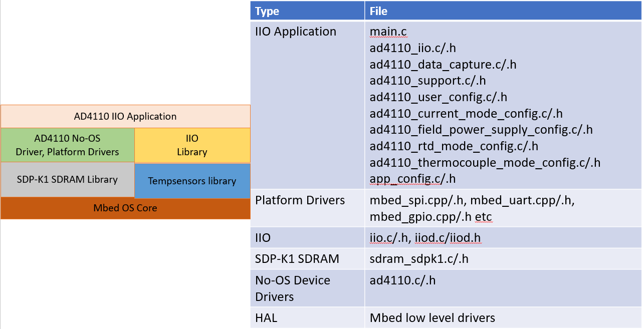
The overview of the entire system is shown below:
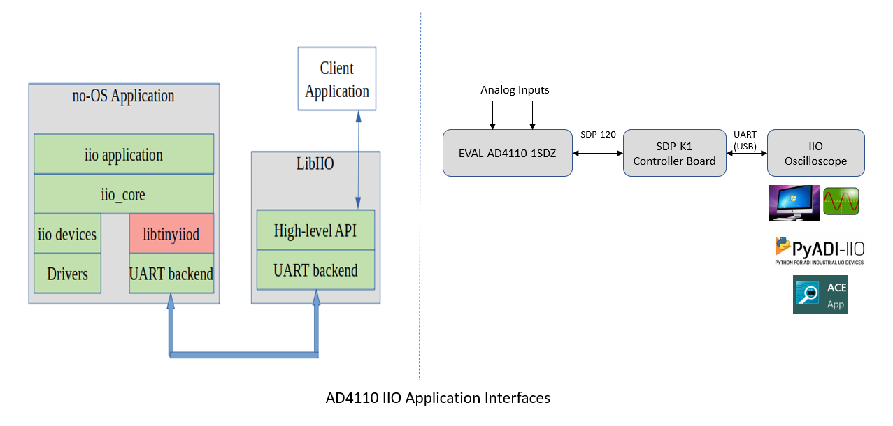
IIO Oscilloscope is used as the client application running on Windows, which is the ADI developed GUI for ADC data visualization and device debug. The interface used for communicating the client application with the firmware application (IIO device) is UART.
Note
SDP-K1 can also support a high speed VirtualCOM port at 1 Mbps or higher for faster data transmission.
The firmware application communicates with the IIO device (AD4110-1) using ADI No-OS drivers and platform driver software layers. SDP-K1 is used as the controller board on which the IIO firmware application runs. The AD4110-1 evaluation board is used for development and testing of this application.
Note
This code has been developed and tested on the SDP-K1 controller board using the on-board Arduino headers. The same code can be used without or with little modification on any Mbed-enabled board that has Arduino header support, such as STM32-Discovery or STM32-Nucleo.
Useful links
Hardware connections
SDP-K1
EVAL-AD4110-1SDZ
Refer to the EVAL-AD4110-1SDZ user guide for the jumper connections to the evaluation board.
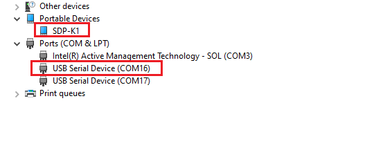
SDP-K1 is powered through the USB connection from the computer. SDP-K1 acts as a serial device when connected to the PC, creating a COM port for connection to the IIO Oscilloscope GUI running on Windows. The COM port assigned to a device can be seen through the Windows Device Manager.
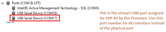
SDP-K1 can also support a high speed VirtualCOM port UART interface
if the USE_VIRTUAL_COM_PORT macro is defined in the firmware
app_config.h file.
Mbed firmware
Quick start to use Mbed IIO firmware
If you have some familiarity with the Mbed platform, the following is a basic list of steps required to start running the code:
Connect the AD4110-1 evaluation board to the SDP-K1 controller board as specified in the hardware connections section.
Connect the SDP-K1 controller board to your computer over USB.
Go to the firmware link above and import the code into Keil Studio.
Ensure the SDP-K1 controller board is selected as the target.
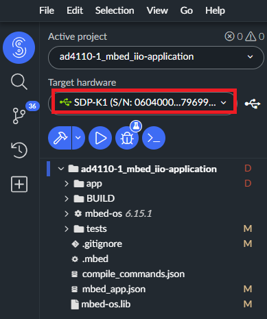
Set the imported project folder as the active project (right-click on the project -> Set Active Project).
Make sure all dependent libraries are imported. This happens automatically when the active project is configured.
Compile the code.
After a successful compile, a binary file is downloaded to your computer. Store this on your drive.
Drag and drop this binary to the USB drive hosted by the SDP-K1 controller board.
After the firmware is loaded, the SDP-K1 initializes the AD4110-1.
Libiio: IIO library
This library provides an abstracted interface for communication between the IIO device (AD4110-1) and the IIO client application (IIO Oscilloscope) without requiring knowledge of low-level hardware details.
IIO Oscilloscope (client)
IIO Oscilloscope is a GUI-based IIO client application for data visualization
and device configuration and debugging. Data from IIO devices (ADCs/DACs) is
transmitted over the Serial/Ethernet/USB link to IIO Oscilloscope through the
abstracted libiio layer.
Evaluating AD4110-1 using the IIO ecosystem
Note
Ensure that hardware connections between the SDP-K1 and the AD4110-1 evaluation board are made properly. Also ensure all software (IIO firmware, Libiio installer, and IIO Oscilloscope installer) are downloaded and installed before attempting to communicate with the AD4110-1 device.
Running IIO Oscilloscope (client)
Open the IIO Oscilloscope application from the start menu and configure the serial (UART) settings. Click Refresh and the AD4110-1 device should appear in the IIO devices list. Click Connect.
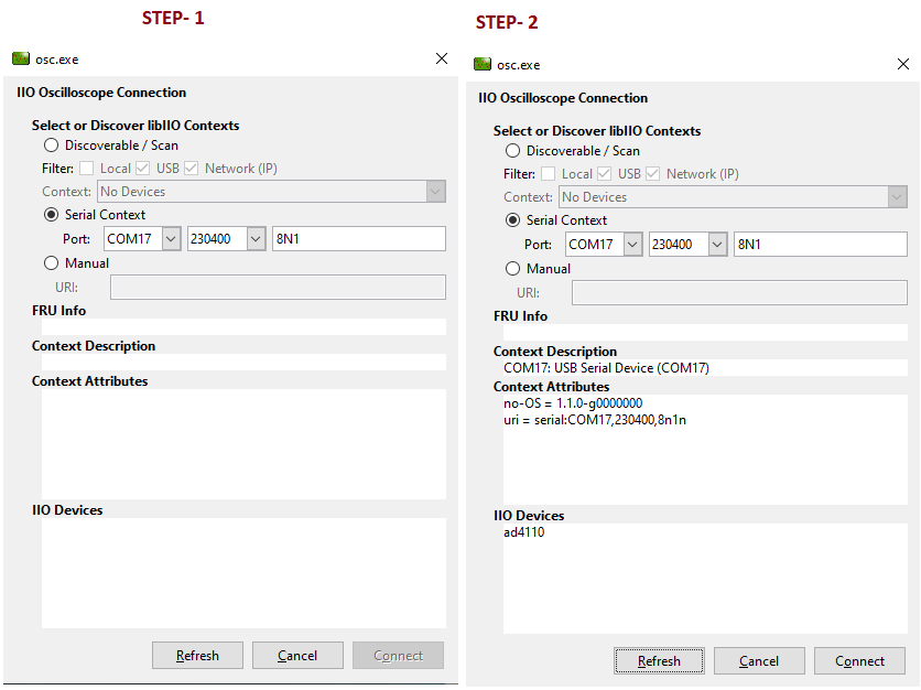
Figure 5 IIO Oscilloscope serial connection and device discovery
Configure/access device attributes
IIO Oscilloscope allows the user to access and configure different device parameters, called Device Attributes. There are two types:
Device attributes (global) - access and configure common device parameters such as oversampling rate and operating mode.
Channel attributes (channel-specific) - access and configure channel-specific parameters such as Scale, Raw, and Offset.
How to read and write an attribute:
To read an attribute, select it from the list or press the Read button.
To write an attribute, enter the value in the Value field and press the Write button. The value to write corresponds to the expected bit-field for that parameter as specified in the datasheet.
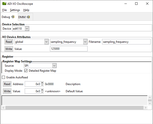
Figure 6 Accessing and configuring device attributes in IIO Oscilloscope
Using the DMM tab to read DC voltage on input channels
The DMM tab can be used to read the instantaneous voltage applied on analog input channels. Select the device and channels to read, then press the start button.
Note
The voltage reading is instantaneous. It is not possible to obtain an RMS AC voltage or averaged DC voltage. When using the DMM tab, do not use the Data Capture or Debug tab simultaneously, as this can affect data capture.
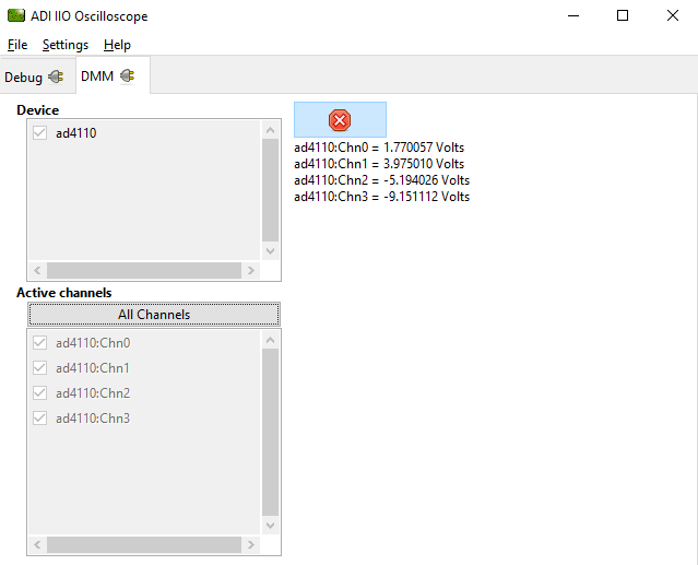
Figure 7 DMM tab showing instantaneous voltage on input channels
The firmware supports the following demo modes. The expected output quantity for each mode is as follows:
Voltage mode - voltage in V
Current mode - current in mA
RTD mode - temperature in °C
Thermocouple mode - temperature in °C
Field Instrument mode - current in mA
The demo modes are selected by redefining the
ACTIVE_DEMO_MODE_CONFIG macro in app_config.h.
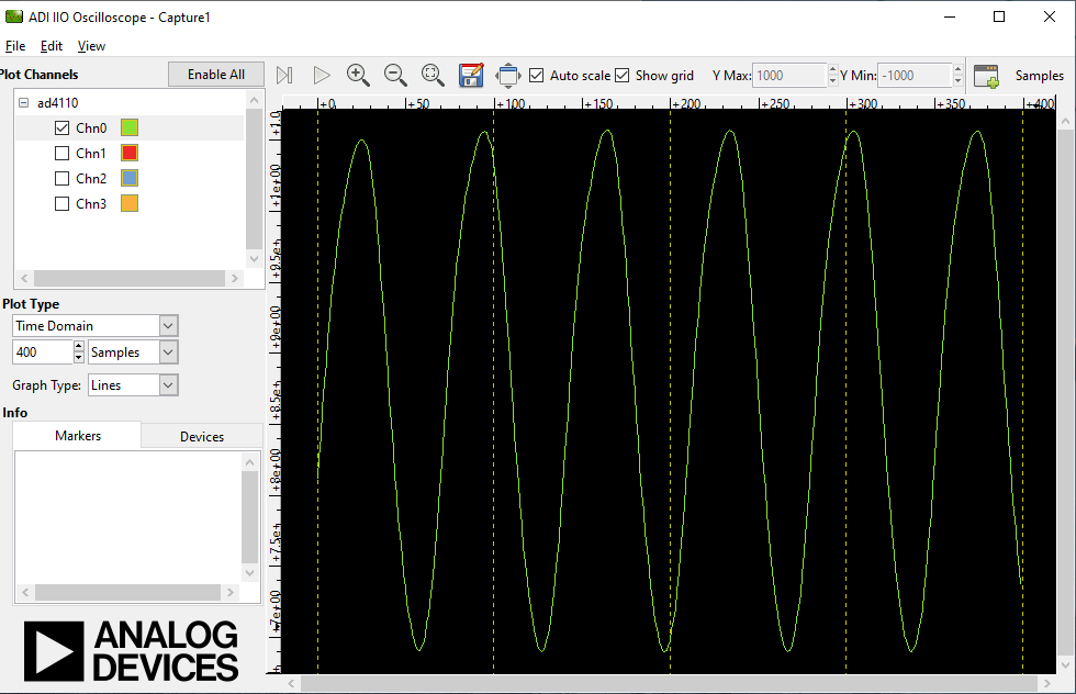
Data capture from IIO device
To capture data from the AD4110-1 IIO device, select the device and channels to capture. The data is plotted as ADC raw value vs. number of samples and is used for visualization. The data is read as-is from the device without any processing. If the user wants to process the data, it must be done externally by capturing data from the serial link on the controller board.
Note
The DMM or Debug tab should not be accessed while capturing data, as this impacts data capture performance.
Time domain:
Frequency domain:
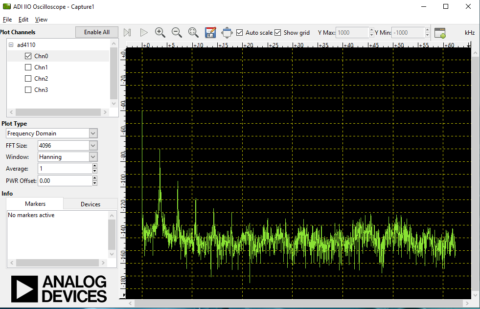
Figure 9 Frequency domain (FFT) data capture in IIO Oscilloscope
Accessing the register map
The Debug tab is used to access device registers in byte mode. Enter the register address in the Address field and click Read to read the register contents, or Write to write to the chosen register.
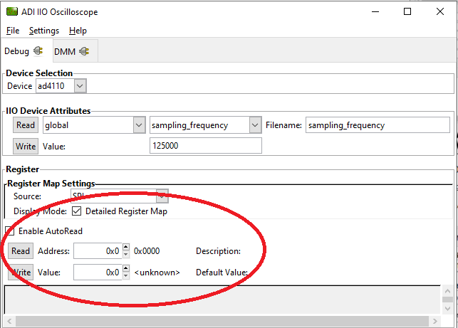
Figure 10 Register map access via the Debug tab in IIO Oscilloscope
Python environment and scripts
Data capture can be achieved with clients other than IIO Oscilloscope.
A possible option using ADI’s pyadi-iio library in Python is
demonstrated in the following sections. The ad4110_data_capture.py
script is capable of achieving the same result.
Setting up the Python environment
Install Python on your local machine. The scripts are developed and tested using Python 3.9.0; version 3.9.0 or later is recommended. Download Python
Once Python is installed, verify it is on the system PATH. Check by running the following in a terminal:
~$
python --versionInstall the
pyadi-iioPython package:~$
python -m pip install pyadi-iio
A detailed guide is available at the pyadi-iio repository.
Install additional support packages from the
scripts/directory:~$
python -m pip install -r requirements.txt
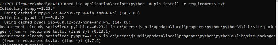
Figure 11 Installing Python support packages from requirements.txt
Modifying and running Python scripts
All Python scripts specific to the AD4110-1 IIO firmware are stored
in the scripts/ folder in the project directory. Scripts must be
executed from this folder.
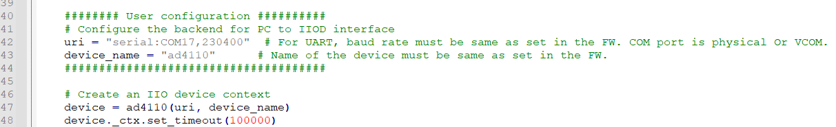
Update the uri interface in the script to match the COM port
assigned to your SDP-K1 device. The default COM port is set to
COM16 in all scripts.
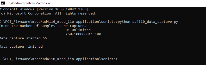
Output from the Python script
While executing ad4110_data_capture.py, the command prompt
requests the number of samples to capture.
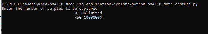
Figure 13 Python script prompting for the number of samples to capture
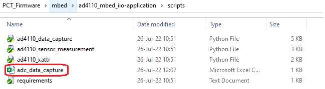
On entering the number of samples n, the data points are stored in
adc_data_capture.csv in the folder where the script is present
upon successful completion of capturing n samples.
Modifying the firmware
The block diagram below shows the AD4110-1 IIO firmware layer. The firmware and device together support five different operating modes: Voltage, Current, Field Power Supply, RTD, and Thermocouple.
File |
Purpose |
|---|---|
|
Selects the demo mode ( |
|
Defines pin mappings for Mbed-based boards. The Arduino connector
is enabled by default; comment out |
|
Included when Voltage Mode is selected (default mode). |
|
Included when Current Mode is selected. |
|
Included when Field Power Supply Mode is selected. |
|
Included when RTD Mode is selected. |
|
Included when Thermocouple Mode is selected. |
|
Defines getter/setter functions for all device and channel attributes. Contains the majority of device-specific functionality. |
|
Defines the data capture implementation for visualizing ADC raw data in IIO Oscilloscope. |
|
No-OS driver files providing the high-level abstracted layer for the AD4110-1 digital interface, including memory map access and data reads in integration with platform drivers. |
Tip
The most common functions of the AD4110-1 family are implemented, but some special functionality may not be covered. Feel free to consult Analog Devices Engineer-Zone for feature requests, feedback, and bug reports.