Quick start
The quick start guides provide step-by-step instructions for an initial system setup of the EVAL-AD4110-1SDZ evaluation board on the supported platforms. Two paths are available: a Windows-based setup using the SDP-B controller board and the AD4110-1 evaluation software, and an FPGA-based setup using the Digilent ZedBoard.
Supported carriers
The EVAL-AD4110-1SDZ connects to carrier boards via the 120-pin SDP connector (J1) or the SPI PMOD connector (J2).
Supported environments
Hardware setup
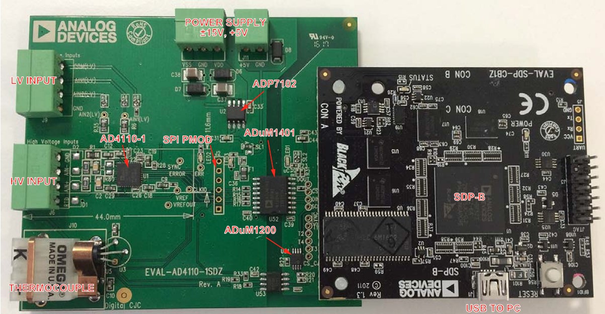
EVAL-AD4110-1SDZ + SDP-B
The evaluation board connects to the SDP-B controller board via the 120-pin connector (J1). Secure the two boards together using the plastic screws and washers provided in the evaluation board kit. Connect ±15 V and GND to J14 on the evaluation board. Connect the SDP-B board to the PC using the USB cable.
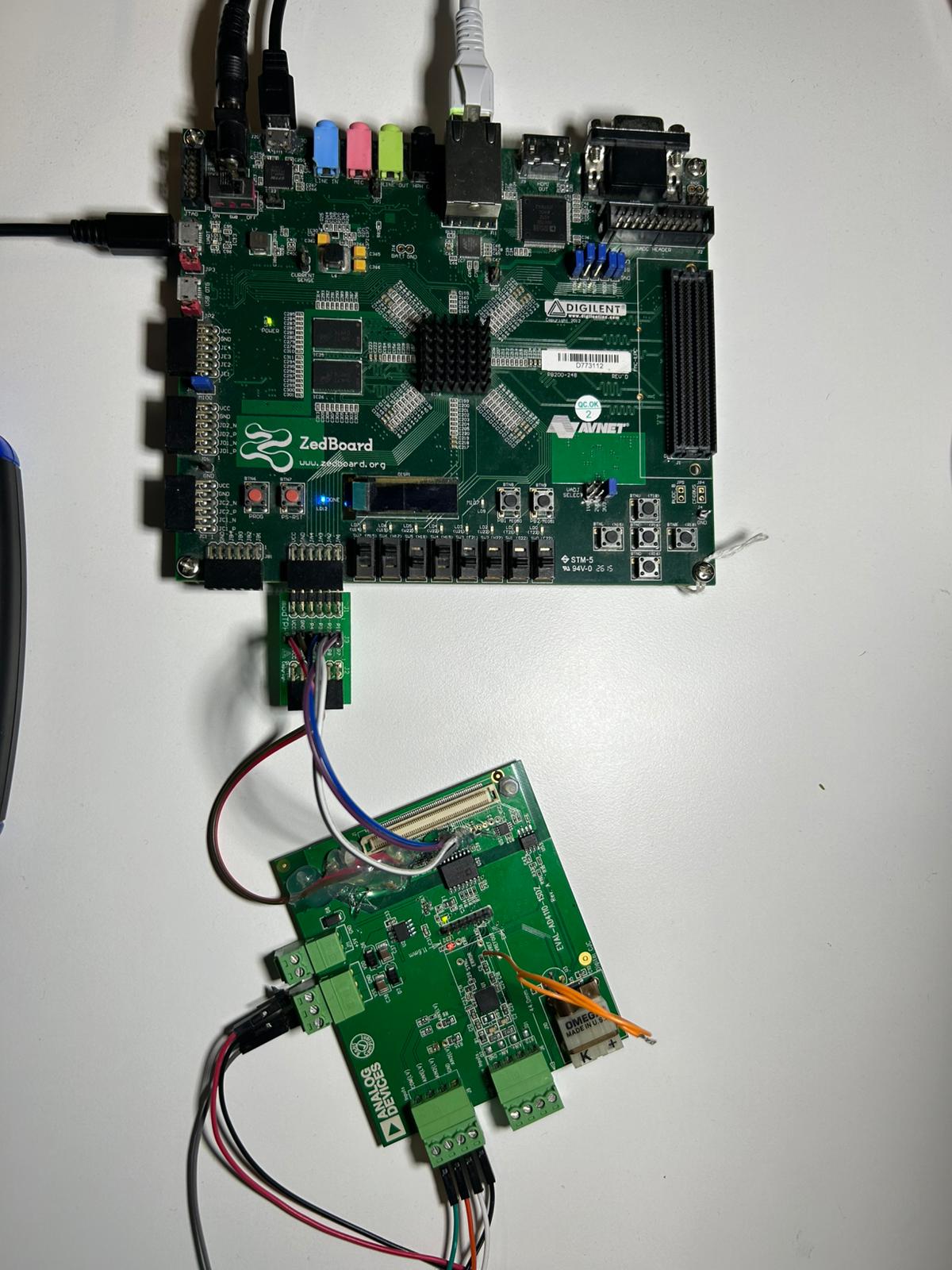
EVAL-AD4110-1SDZ + ZedBoard
The evaluation board connects to the ZedBoard via the SPI PMOD connector (J2) on the evaluation board and the PMOD headers on the ZedBoard. Connect the SPI signals using individual jumper wires as described in ZedBoard Quick Start.