User guide
Hardware guide
Board overview
The EVAL-AD4110-1SDZ evaluation board supports two controller board configurations: the Digilent ZedBoard for baremetal evaluation using No-OS, and the SDP-B controller board.
ZedBoard
The EVAL-AD4110-1SDZ connects to the ZedBoard via the SPI PMOD connector (J2) on the evaluation board and the JA/JB PMOD headers on the ZedBoard. The evaluation board receives 3.3 V logic power from the ZedBoard PMOD and requires an external ±15 V supply at J14 for the high-voltage analog front end. See ZedBoard Quick Start for the full signal connection table.
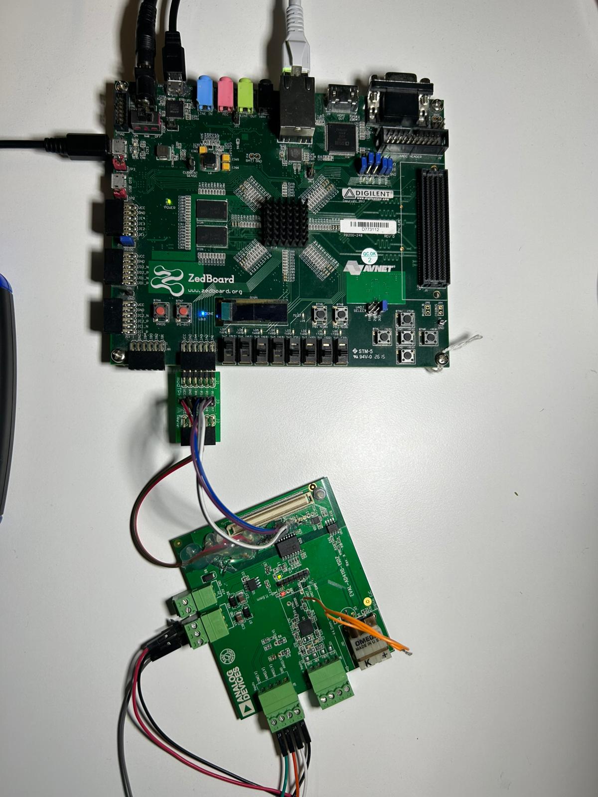
Figure 1 EVAL-AD4110-1SDZ hardware configuration with ZedBoard
SDP-B (legacy)
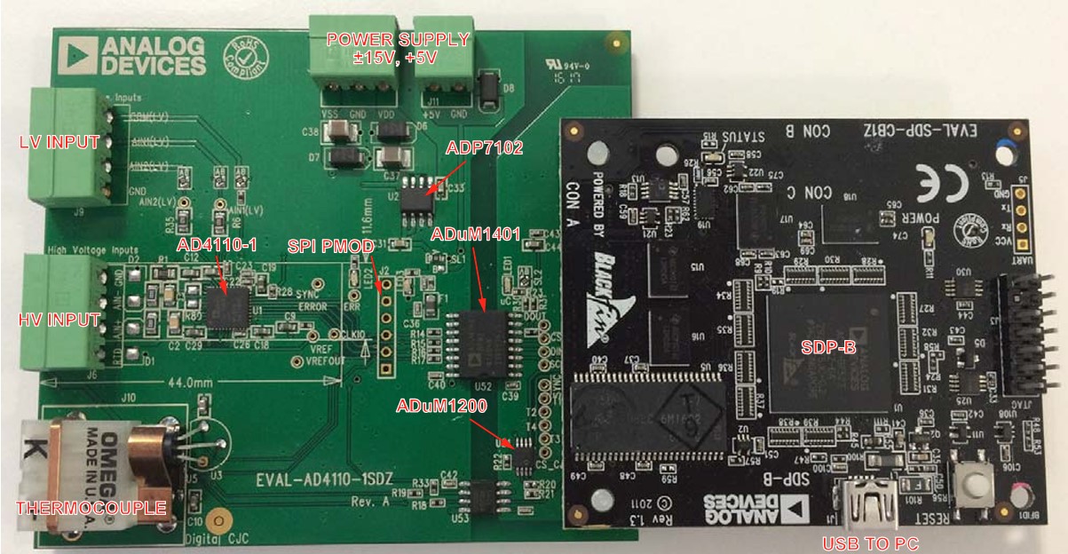
The EVAL-AD4110-1SDZ mounts directly onto the SDP-B controller board via the 120-pin connector (J1). The SDP-B board provides the USB communication link between the PC and the evaluation board.
Power supplies
The EVAL-AD4110-1SDZ requires external voltage supplies applied to connector J14 regardless of the controller board used:
Connect +15 V to the VDD pin on J14
Connect −15 V to the VSS pin on J14
Connect 0 V to the GND pin on J14
A ±15 V power supply is recommended; ±12 V to ±20 V is acceptable. The 5 V supply required by the evaluation board is generated on-board by the ADP7102 low dropout regulator (LDO) from the 15 V input.
When used with the ZedBoard, the evaluation board digital logic receives 3.3 V from the ZedBoard PMOD (JA6). The ±15 V supply at J14 is still required to power the high-voltage analog front end.
When used with the SDP-B, the SDP-B board is powered via the USB connection to the PC and runs at 3.3 V.
Schematic, PCB Layout, Bill of Materials
Design support files for the EVAL-AD4110-1SDZ evaluation board, including schematics, PCB layout, and bill of materials, are available on the AD4110-1 product page. Refer to the User Guide for the full evaluation board user guide.
Software guide
ZedBoard
The ZedBoard runs the AD4110-1 No-OS baremetal application on the Zynq ARM
core alongside the HDL reference design in the FPGA fabric. The FPGA is
programmed and the application is loaded via JTAG using Xilinx xsct.
Output and status messages are monitored over UART at 115200 baud.
Refer to ZedBoard Quick Start for the full setup procedure including HDL build instructions, hardware wiring, and JTAG programming steps.
SDP-B evaluation software (legacy)
The EVAL-AD4110-1SDZ is supported by the AD4110-1 evaluation software for Windows, which communicates with the board through the SDP-B controller board via USB.
The AD4110-1 evaluation software provides a graphical interface for configuring and evaluating the AD4110-1 device. It supports multiple demo modes that automatically configure the device for the connected sensor type.
The available demonstration modes are:
±10 V transducer (voltage mode)
4 mA to 20 mA transmitter (current mode)
4 mA to 20 mA transmitter requiring field power
Thermocouple
3-wire RTD
Refer to SDP-B Quick Start for step-by-step installation and setup instructions.