ZedBoard Quick Start
All the products described on this page include ESD (electrostatic discharge) sensitive devices. Electrostatic charges as high as 4000V readily accumulate on the human body or test equipment and can discharge without detection. Although the boards feature ESD protection circuitry, permanent damage may occur on devices subjected to high-energy electrostatic discharges. Therefore, proper ESD precautions are recommended to avoid performance degradation or loss of functionality. This includes removing static charge on external equipment, cables, or antennas before connecting to the device.
This guide provides step-by-step instructions for setting up the EVAL-AD4110-1SDZ on the Digilent ZedBoard using the ADI HDL reference design and No-OS baremetal firmware.
Required hardware
EVAL-AD4110-1SDZ evaluation board
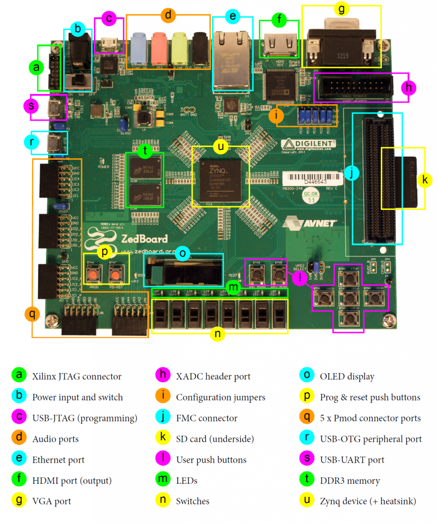
Digilent ZedBoard (Zynq-7000 ARM/FPGA SoC development board)
Jumper wires for PMOD connections
External ±15 V power supply for the evaluation board
Micro-USB cable for UART console access
Micro-USB cable for JTAG
Required software and files
The following must be available before programming the ZedBoard:
HDL hardware platform export (
system_top.xsa), built from the Build an HDL projectNo-OS AD4110-1 project: projects/ad4110
Xilinx Vitis (includes
xsctand the ARM cross-compilation toolchain)
More details can be found at Prerequisites.
Building the HDL project
The design is built on ADI’s generic HDL reference design framework. To build from source, clone the HDL repository and build the project:
~$
cd hdl/projects/ad4110/zed
~/hdl/projects/ad4110/zed$
make
A comprehensive build guide is available in the Build an HDL project user guide.
Setting up the hardware
The EVAL-AD4110-1SDZ connects to the ZedBoard via the SPI PMOD connector (J2) on the evaluation board and the JA/JB PMOD headers on the ZedBoard. The evaluation board is powered by the 3.3 V voltage from the ZedBoard PMOD (LED1 green indicates a valid SDP connection). The evaluation board also requires ±15 V applied to J14 for the high-voltage analog front end (LED3 green indicates 5 V supply).
Follow these steps in order to avoid damaging components:
Ensure the ZedBoard and the evaluation board are powered off.
Connect ±15 V and GND to J14 on the evaluation board.
Wire the SPI and GPIO signals from J2 on the evaluation board to the ZedBoard PMOD headers as listed in the AD4110 HDL project.
Connect the micro-USB cable to the UART port on the ZedBoard.
Connect the JTAG cable from the ZedBoard to the host PC.
Configure a UART terminal (PuTTY, Tera Term, or Minicom) at 115200 baud, 8N1.
Power on the ZedBoard.
Power on the evaluation board external supply.
Verify that LED3 (green) on the evaluation board is illuminated, indicating 5 V supply is present.
Navigate to the no-OS directory in the AD4110-1 project and run
make runto program the FPGA.
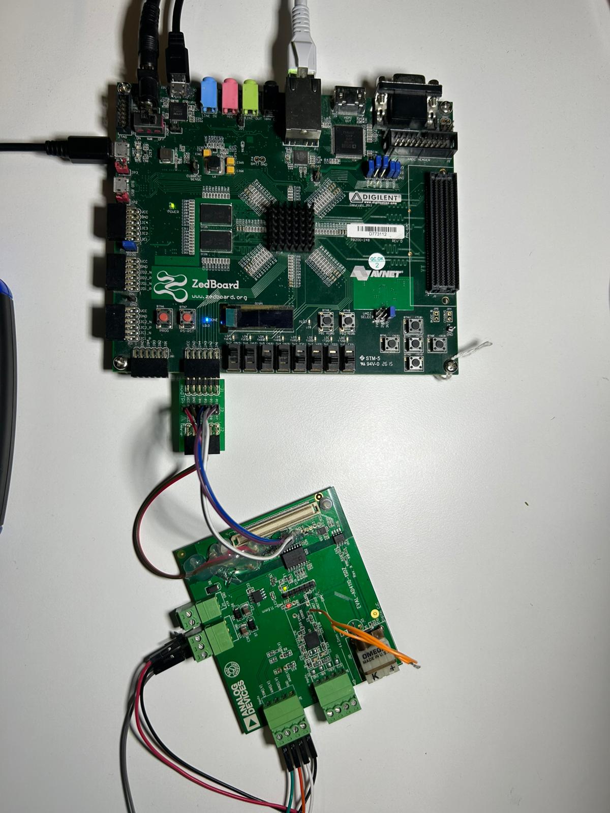
Figure 2 Completed EVAL-AD4110-1SDZ and ZedBoard hardware setup
Verifying the setup
Once the No-OS application is running, the UART terminal displays the initialization output.
Note
A signal source is required at the analog input connector (J6 for high voltage, J8 for low voltage, J10 for thermocouple) before capturing meaningful data.