SDP-B Quick Start
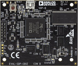
Figure 1 Analog Devices System Demonstration Platform SDP-B controller board
All the products described on this page include ESD (electrostatic discharge) sensitive devices. Electrostatic charges as high as 4000V readily accumulate on the human body or test equipment and can discharge without detection. Although the boards feature ESD protection circuitry, permanent damage may occur on devices subjected to high-energy electrostatic discharges. Therefore, proper ESD precautions are recommended to avoid performance degradation or loss of functionality. This includes removing static charge on external equipment, cables, or antennas before connecting to the device.
This guide provides step-by-step instructions for setting up the EVAL-AD4110-1SDZ with the SDP-B controller board and the AD4110-1 evaluation software on Windows.
Required hardware
EVAL-AD4110-1SDZ evaluation board
SDP-B controller board
USB cable
External ±15 V power supply (±12 V to ±20 V acceptable)
Signal source
Required software
AD4110-1 evaluation software
ADI SDP board drivers (installed as part of the evaluation software setup)
More details on what you need can be found at Prerequisites.
Software installation
Important
Install the evaluation software before connecting the SDP-B board to the PC. The PC must be restarted after installation to complete the driver setup.
Installing the AD4110-1 evaluation software
Obtain the AD4110-1 evaluation software installer from the EVAL-AD4110-1SDZ product page.
Ensure the SDP-B board is not connected to the PC. Unzip the evaluation software zip file.
Double-click setup.exe to start the installation.
If a User Account Control dialog appears, click Yes to allow the installation to proceed.
Select the installation location and click Next>>.
Read the license agreement, select I accept the License Agreement, and click Next>>.
Review the installation summary and click Next>> to begin.
Click Next>> when the installation complete dialog appears.
Installing the SDP-B board drivers
After the evaluation software installation completes, the SDP-B board driver setup wizard launches automatically.
Ensure the SDP-B board is disconnected from the PC. Close all other applications and click Next>>.
Select the driver installation location and click Install.
If a Windows Security dialog appears, click Install to confirm.
Click Finish when the driver installation is complete.
Restart the PC before using the evaluation board.
Verifying the SDP-B connection
After restarting, verify that the SDP-B drivers are installed correctly using the Windows Device Manager:
Click Start, Control Panel, then Device Manager.
Expand ADI Development Tools.
Confirm that Analog Devices System Demonstration Platform SDP-B appears in the list, indicating the driver is installed and the board is recognized.
Hardware setup
Follow these steps to assemble the hardware before powering on:
Connect the EVAL-AD4110-1SDZ evaluation board to Connector A (CON A) on the SDP-B board using the 120-pin connector.
Secure the two boards together
Apply the external ±15 V power supply to J14 on the evaluation board:
Connect +15 V to the VDD pin.
Connect −15 V to the VSS pin.
Connect 0 V to the GND pin.
Connect the USB cable from the SDP-B board to the PC.
Power on the external supply.
Verify that LED3 (green) on the evaluation board is illuminated, indicating 5 V is present on the board.
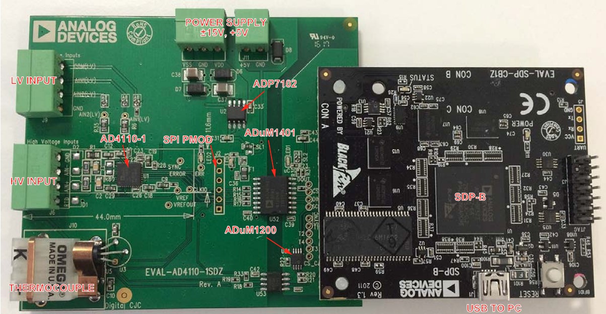
Figure 2 Completed EVAL-AD4110-1SDZ and SDP-B hardware setup
Running the evaluation software
From Start, select Programs -> Analog Devices -> AD4110-1_SDZ, then AD4110-1. The main window of the software opens.
If the SDP-B board is not connected when the software launches, a connectivity error dialog appears. Connect the board to the USB port, wait a few seconds, click Rescan, and follow the on-screen instructions.
When the SDP-B board is detected, a confirmation dialog displays “1 matching system found. LED1 is flashing on matching board.” Click Select.
LED1 (green) on the evaluation board illuminates, confirming a valid SDP connection.
The status bar at the bottom of the main window shows Evaluation Board Initialized.
Selecting a demo mode and sampling
From the main window menu bar, click Mode -> Demo Modes, and select the sensor type connected to the input:
±10V Mode - for ±10 V voltage transducer
4-20mA Mode - for 4 mA to 20 mA current transmitter
4-20mA Field Instrument - for current transmitter requiring field power
TC Mode - for thermocouple input
RTD Mode - for 3-wire RTD sensor
The evaluation software and AD4110-1 device automatically configure for the selected sensor type.
Connect the required sensor to the appropriate input connector:
Voltage/current sensors: J6 (high voltage universal input)
Low voltage signals: J8
Thermocouple: J10
Click Sample to begin acquiring data. The waveform is displayed in the Waveform tab.