DC2135A + MAX32666FTHR Quick Start
All the products described on this page include ESD (electrostatic discharge) sensitive devices. Electrostatic charges as high as 4000V readily accumulate on the human body or test equipment and can discharge without detection. Although the boards feature ESD protection circuitry, permanent damage may occur on devices subjected to high-energy electrostatic discharges. Therefore, proper ESD precautions are recommended to avoid performance degradation or loss of functionality. This includes removing static charge on external equipment, cables, or antennas before connecting to the device.
This guide covers no-OS evaluation of the LTC2378-20 using the DC2135A demonstration board and the MAX32666FTHR microcontroller platform.
Overview
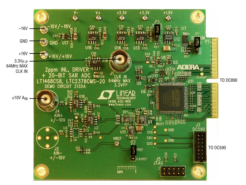
The DC2135A operates from ±16V supplies. The LTC2378-20 ADC itself runs from a 2.5V regulated supply generated on-board. The board provides all signal conditioning and reference circuitry needed to evaluate the ADC at up to 800 kSPS.
Hardware needed
DC2135A evaluation board
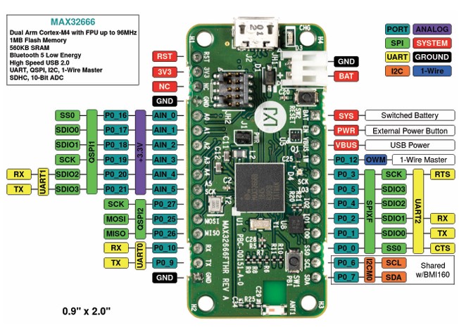
MAX32666FTHR microcontroller board
External ±16V DC power supply
USB cable (host PC to MAX32666FTHR)
Low-noise signal source for the analog input (J4 SMA, ±10V range)
Jumper wires for SPI interconnect
DC2135A jumper settings
For full jumper details refer to the DC2135A product page.
Warning
Set JP3 to 3.3V when interfacing the DC2135A with the MAX32666FTHR. Using the wrong VCCIO setting may damage the connected hardware.
Hardware connections
For detailed hardware connection information between the DC2135A and the MAX32666FTHR, refer to the no-OS ltc2378 project.
After making the connections:
Apply ±16V to the DC2135A power terminals
Connect the USB cable from the MAX32666FTHR to the host PC
Connect the analog signal source to the J4 SMA connector on DC2135A
Using no-OS
The no-OS ltc2378 project supports two example configurations: a basic example for verifying ADC operation, and an IIO example that launches a server for remote connection with IIO Oscilloscope.
Building the no-OS project
Clone the no-OS repository and navigate to the project directory:
~$
cd no-OS/projects/ltc2378
The project common initialization data is located at projects/ltc2378/src/common and platform-specific configuration macros are in projects/ltc2378/src/platform.
Basic example
The basic example initializes the LTC2378-20 and performs the start-up sequence, printing raw ADC samples over the serial console.
To build and flash:
~/no-OS/projects/ltc2378$
make EXAMPLE=basic PLATFORM=maxim TARGET=max32665
IIO example
The IIO example launches an IIOD server on the MAX32666FTHR so that IIO Oscilloscope can connect remotely and capture data.
To build and flash:
~/no-OS/projects/ltc2378$
make EXAMPLE=iio PLATFORM=maxim TARGET=max32665
Once the firmware is running, open IIO Oscilloscope on the host PC and connect to the board using its serial or network URI. For information on using IIO Oscilloscope with no-OS servers, see:
Note
The no-OS IIO application and the LTC2378-20 IIO driver handle all back-end logic for the IIO server. The IIO example source is at projects/ltc2378/src/examples/iio.