DIY 48V Battery Pack for Electronic Vehicles
Building a 48V lithium-ion battery pack is an innovative and cost-effective way to power an electric vehicle (EV), e-bike, or solar storage system. By assembling individual cells into a well-balanced pack, you can achieve a high-performance, rechargeable power source tailored to your specific needs.
This guide will walk you through the design, assembly, and safety considerations involved in creating a reliable and efficient 48V battery pack using 18650 – 3.7V lithium-ion cells. This will show you the hardware and software setup on how to monitor cell voltages and battery pack current and voltage using the EVAL-ADBMS6830BMSW and EVAL-ADBMS2950-BASIC.
Features and Highlights
Accurate voltage and current measurement
Highly scalable and ease of integration
Robust isoSPI capability implementable in daisy chain high count
Isolated power supply between microcontroller and battery monitoring ICs
Compatible with EVAL-ADBMS6822 dual master isoSPI board
With PC-based software for control and data analysis using Broad Market Browser BMS GUI
Basic embedded code functions for cell monitoring and diagnostics
Scope and Limitations
Scope of Target End-Application
This guide focuses on building a DIY 48V lithium-ion battery pack intended for demo use to mimic the batteries in electric vehicles (EVs), e-bikes, or other similar applications that require a reliable and efficient power source. The battery pack will be constructed using 18650 – 3.7V lithium-ion cells and monitored using the EVAL-ADBMS6830BMSW, a 16-channel battery cell monitor. The demo provides basic cell voltage and current monitoring, offering accurate measurements to ensure the battery pack operates within safe parameters.
Limitations
This demo design is not intended for direct deployment or integration into final commercial products. It is solely intended as a demo application for educational and prototyping purposes.
The battery pack’s actual performance may vary depending on the quality of the lithium-ion cells used, the assembly quality, and the accuracy of the BMS calibration.
The design assumes that users have a certain level of technical expertise, including knowledge of battery construction and soldering skills. Adequate care and experience should be applied when working with lithium-ion cells due to their sensitive nature and potential safety risks.
The software provided with the EVAL-ADBMS6830BMSW and associated boards is intended for use with specific hardware and may not work with different or custom hardware configurations without modification.
Reference Design and Solution
EVAL-ADBMS6830BMSW 16-Channel Battery Cell Monitor
The EVAL-ADBMS6830BMSW is a full-featured evaluation board for the ADBMS6830B, a 16-channel battery stack monitor for broad market applications. This board allows multiple boards to be linked through a single twisted pair wire interface (isoSPI) to monitor a long series of cells in a stack. It provides access to full channel monitoring to all cells going to battery pack either in the supply line or in the V+ to V- line. The evaluation board also features reversible isoSPI that can access either path to do measurement functions and serve as a redundant communication path.
EVAL-ADBMS2950-BASIC Battery Pack Monitor
The EVAL-ADBMS2950-BASIC battery pack monitoring evaluation board features the ADBMS2950, a bidirectional current monitor, with 12 buffered high impedance voltage sense inputs, linked through a 2-wire isolated serial interface (isoSPI). This board also features reversible isoSPI, enabling a redundant communication path.
The EVAL-ADBMS2950-BASIC board can be operated on the same isoSPI daisy-chain with other ADBMS2950B and ADBMS6830B devices.
EVAL-ADBMS6822 Dual isoSPI Adapter
The EVAL-ADBMS6822 is a dual SPI to 2-wire isolated serial port interface (isoSPI) adapter featuring the ADBMS6822. This board allows multiple ADBMS68xx battery monitors through daisy-chain connections. The EVAL-ADBMS6822 evaluation board also features reversible isoSPI, which enables a redundant path to the peripheral units. The PCB components and DuraClik connectors are optimized for low electromagnetic interference (EMI) susceptibility and emissions.
EVAL-SDP-CK1Z (SDP-K1) Controller Board
The EVAL-SDP-CK1Z Controller Board provides a means of communicating with the PC from the other BMS boards in the Cellpack BMS System. The SDP-K1 provides USB connectivity through a USB 2.0 high speed connection to the computer, allowing users to evaluate components on this platform from a PC application. The SDP-K1 is based on an STM32F469NIH6 Arm® Cortex®-M4 microcontroller with the peripheral communication lines available to the daughter board(s) through a 120-pin small footprint connector and Arduino® Uno-compatible headers.
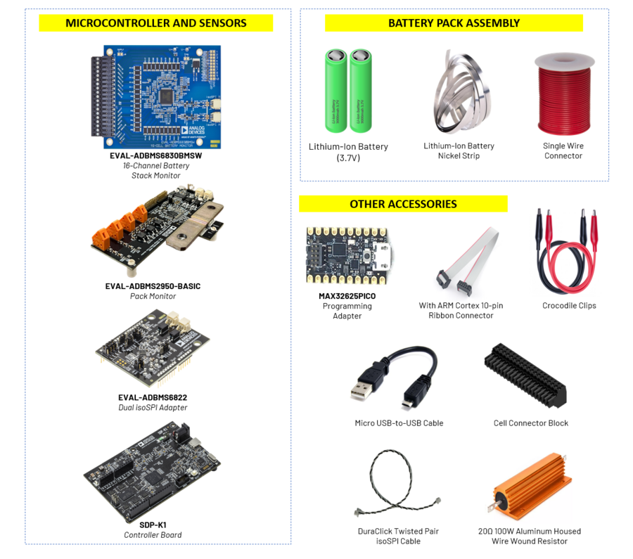
Material Requirements
QTY |
MATERIAL |
|---|---|
39 pcs |
18650 – 3.7V Lithium-Ion Battery |
1 roll |
Lithium-Ion Nickel Strip |
1 roll |
Single Wire Connector |
1 pc |
EVAL-ADBMS6830BMSW Board |
1 pc |
EVAL-ADBMS2950-BASIC Board |
1 pc |
EVAL-ADBMS6822 Board |
1 pc |
SDP-K1 Board |
1 pc |
20Ω 100W Aluminum Housed Wire Wound Resistor (may vary depending on the battery pack’s current capacity) |
1 pc |
Cell Connector Blocks (included in the EVAL-ADBMS6830BMSW Kit) |
1 pc |
MAX32625PICO Programmer Board with 10-pin SWD Ribbon Cable |
2 pcs |
DuraClick Twisted Pair isoSPI Cable |
3 pcs |
Test Leads Alligator Double-Ended Crocodile Clips |
1 pc |
Micro USB-to-USB Cable |
1 pc |
Type C-to-USB Cable |
Setup Guide
This section details the entire setup procedure broken down into hardware and software steps.

Hardware Setup
Battery Pack Assembly
In this demo, 39 batteries will be assembled to create a 48V battery pack.
Determine the Number of Batteries
The number of cells in series N can be calculated by dividing the total voltage needed (48V) by the voltage of one cell (3.7V).
In this example, 13 cells are required to build a 48V battery pack. Each cell consists of 3 batteries connected in parallel, resulting in a total of 39 batteries for the entire pack.
Arrange the batteries according to the picture below.

- Connecting the Batteries
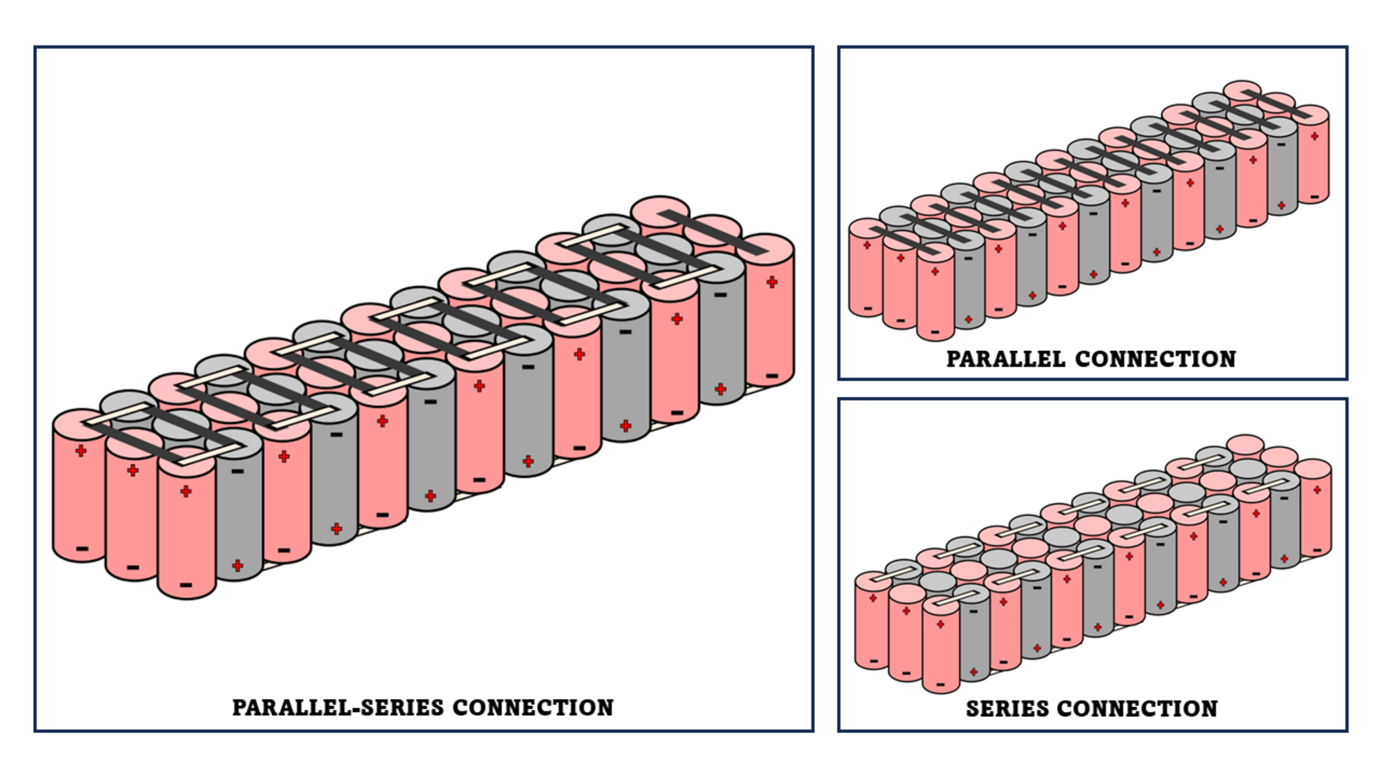
Make a Parallel Connection. Connect 3 batteries in parallel by linking all positive terminals and all negative terminals using the lithium-ion battery nickel strip. Use a spot welder, ensuring a strong and reliable connection. Repeat this process to form 13 cells.
After completing the 13 cells, make a Series Connection by connecting the positive terminal of one cell to the negative terminal of the next cell. Continue this process until all 13 cells are connected in series.
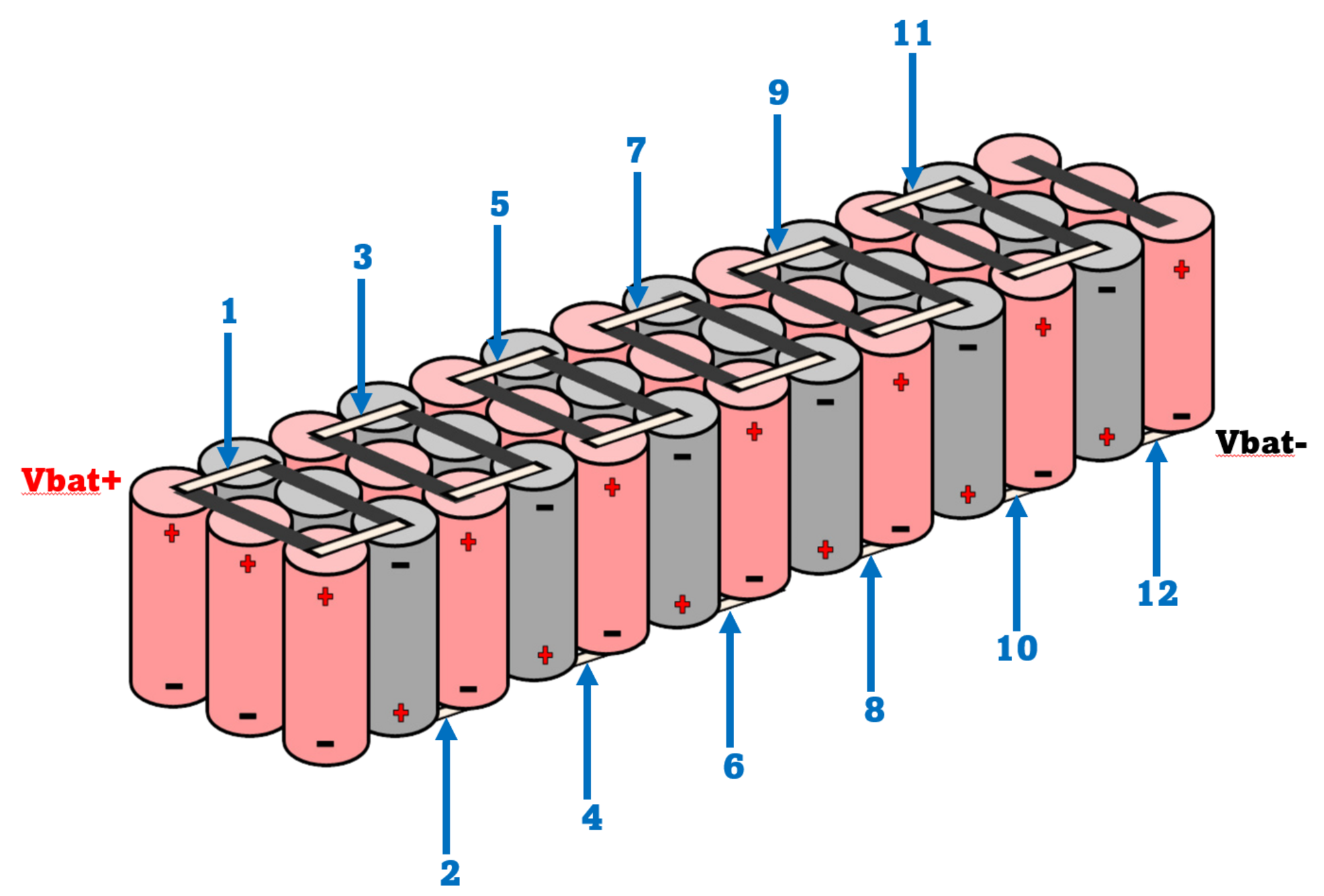
Adding Cell Terminal Strips
Cut and prepare the appropriate lengths of nickel strips to be used as terminal connections.
Attach a nickel strip based on the picture below. Use a spot welder or suitable method to securely weld the strip to the terminal.
Solder a single wire cable on each nickel strip terminal except for Vbat+ and Vbat-.
Insulation and Final Assembly
Ensure all connections are secure and properly insulated to prevent short circuits.
Use heat shrink tubing or electrical tape to cover exposed connections.
Place the battery pack in a suitable enclosure for protection and ease of handling.
Thickness of Nickel Strip / Type of Nickel Strip |
— |
0.1 mm |
0.12 mm |
0.15 mm |
0.2 mm |
0.3 mm |
|---|---|---|---|---|---|---|
Nickel Plated Steel |
Current |
15 |
25 |
45 |
65 |
65 |
Nickel Plated Steel |
Pulse |
1P |
1P |
2P |
2P |
2P + 4P + 6P |
Pure Nickel Strip |
Current |
25 |
25 |
65 |
95 |
– |
Pure Nickel Strip |
Pulse |
1P |
1P |
2P |
2P |
– |
Warning
Refer to the diagram above and make sure to connect the bottom part of the pack.
Important
Before connecting lithium-ion cells in parallel, ensure that all cells have the same or very close voltage levels (within ±0.05V). Connecting cells with different charge levels can result in large inrush currents, potentially causing: sparks or overheating, permanent cell damage, fire or thermal runaway, reduced battery life.
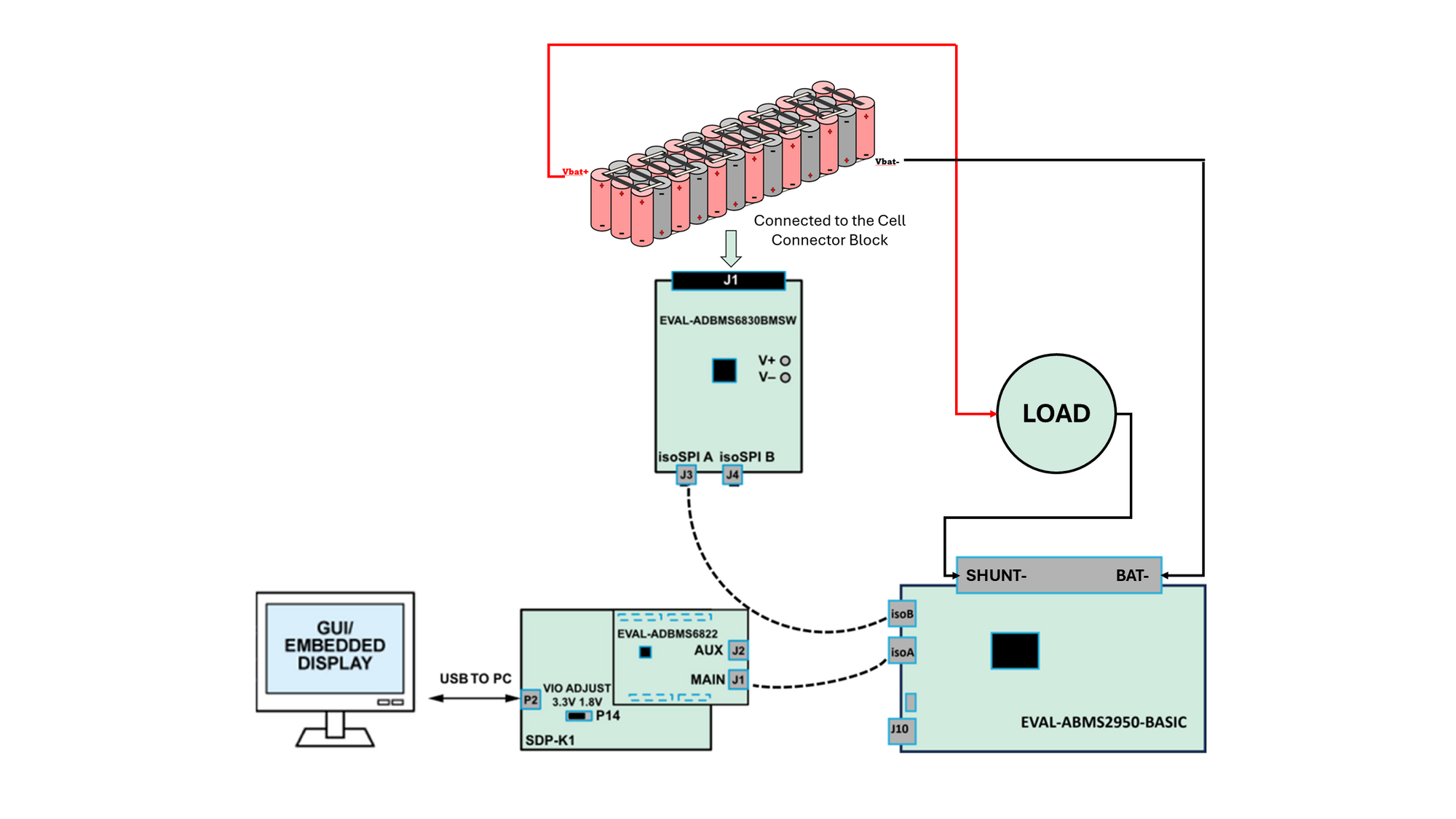
Connection Setup
Set the P14 jumper of the SDP-K1 to the 3.3 V position.
Connect the EVAL-ADBMS6822 dual isoSPI adapter to the EVAL-SDP-CK1Z (SDP-K1) controller board through the Arduino headers.
Connect the SDP-K1 (P2) to the Host PC using a USB cable.
Connect the EVAL-ADBMS6822 (J1) to the EVAL-ADBMS2950-BASIC (isoA) using the 2-wire twisted-pair patch cable from the main DuraClik connector to isoSPI A DuraClik connector.
Connect the EVAL-ADBMS2950-BASIC (isoB) to the EVAL-ADBMS6830BMSW (J3) using the 2-wire twisted-pair patch cable from the main DuraClik connector to isoSPI A DuraClik connector.
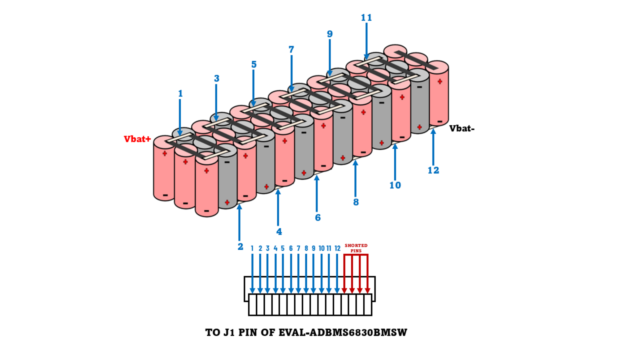
Using the single wire cables attached to each cell terminals, connect each battery cell to the cell connector block. Refer to the diagram to short any unused ports in the block.
Using the test leads alligator double-ended crocodile clips, connect the Shunt- of the EVAL-ADBMS2950-BASIC to one end of the resistor load.
Using another crocodile clip, connect the Bat- of EVAL-ADBMS2950-BASIC by clipping the other end of the crocodile clip to Vbat- of the battery pack.
Then attach the cell connector block to the EVAL-ADBMS6830BMSW through J1 port. Once attached, connect the Vbat+ of the battery pack to the other end of the resistor load. Refer to the diagram below.
Warning
Make sure to complete all hardware and software dependencies first before connecting the battery to the EVAL-ADBMS6830BMSW and the load for safety.
Software Setup
Note
The AD-CELLPACKBM-SL comes complete with firmware examples and easy-to-use application GUI.
Access the software resources and see the setup procedure in the Software User Guide
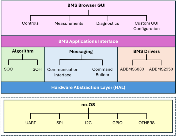
Software Stack
Demo Results
Running the Setup
Follow the instructions provided above to set up the hardware components. Ensure all connections are secure and aligned with the diagram and specifications.
Open the BMS Browser GUI either by searching for it in the Start Menu or using the shortcut on the Desktop.
Upon launching, a console window will appear to display background information.
Two new tabs will open in the default browser on the PC, with the User Guide tab as the default.
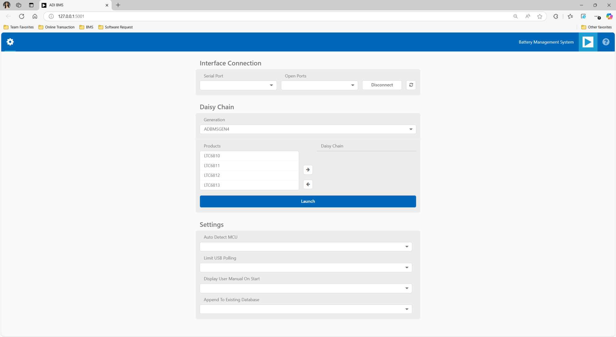
Switch to the alternative tab to access the BMS Browser configuration page, which should be displayed.
Ensure that the SDP-K1 is connected to the PC via the USB-C cable on P10. The Blue LED, D31 will illuminate when powered.
Go to the Interface Connection section and select the COM port associated with the SDP-K1.
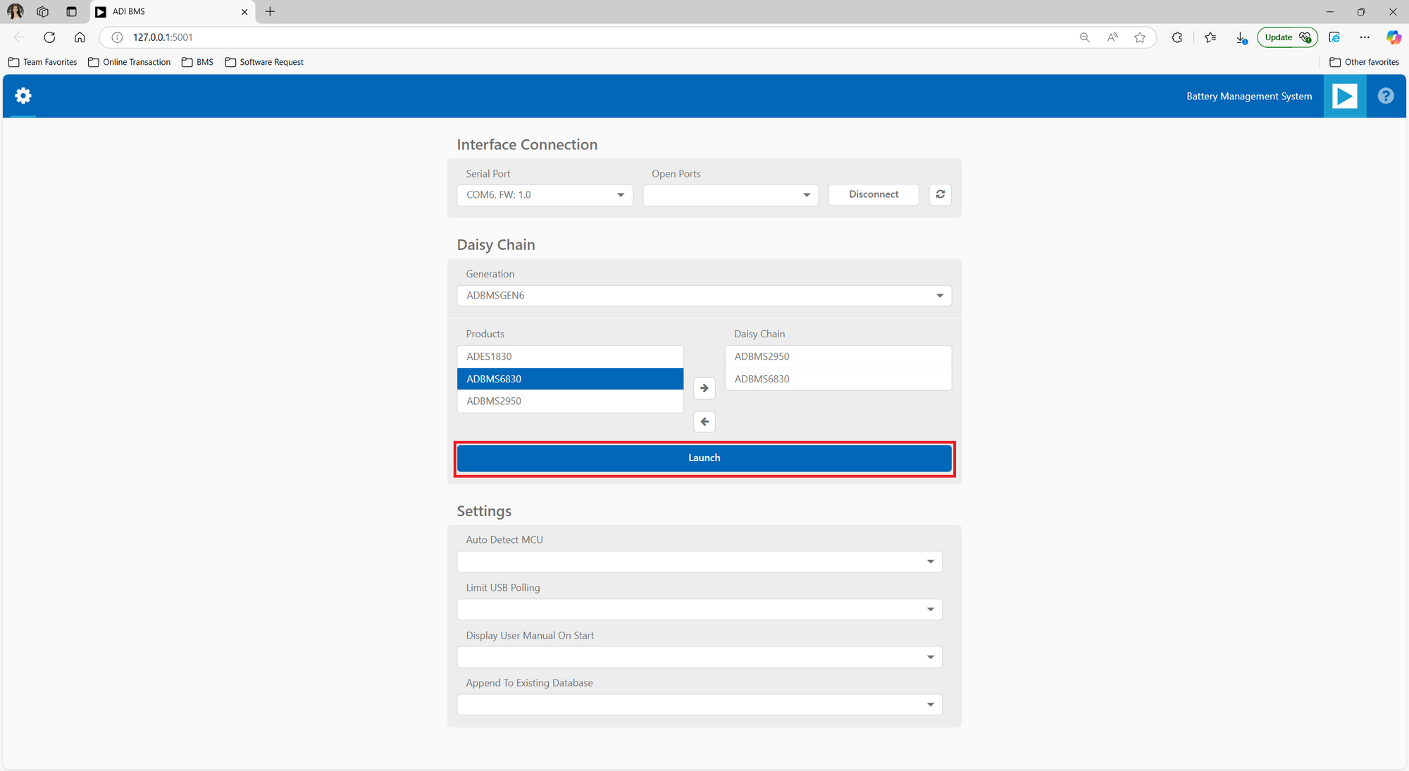
Under the Daisy Chain section, ensure the Generation drop-down box is set to ADBMSGEN6.
From the Products list, select the ADBMS2950, then click on the right arrow to add it to the Daisy Chain. Then select the ADBMS6830 and add it as well in the daisy chain. Settings can remain as default.
Click Launch.
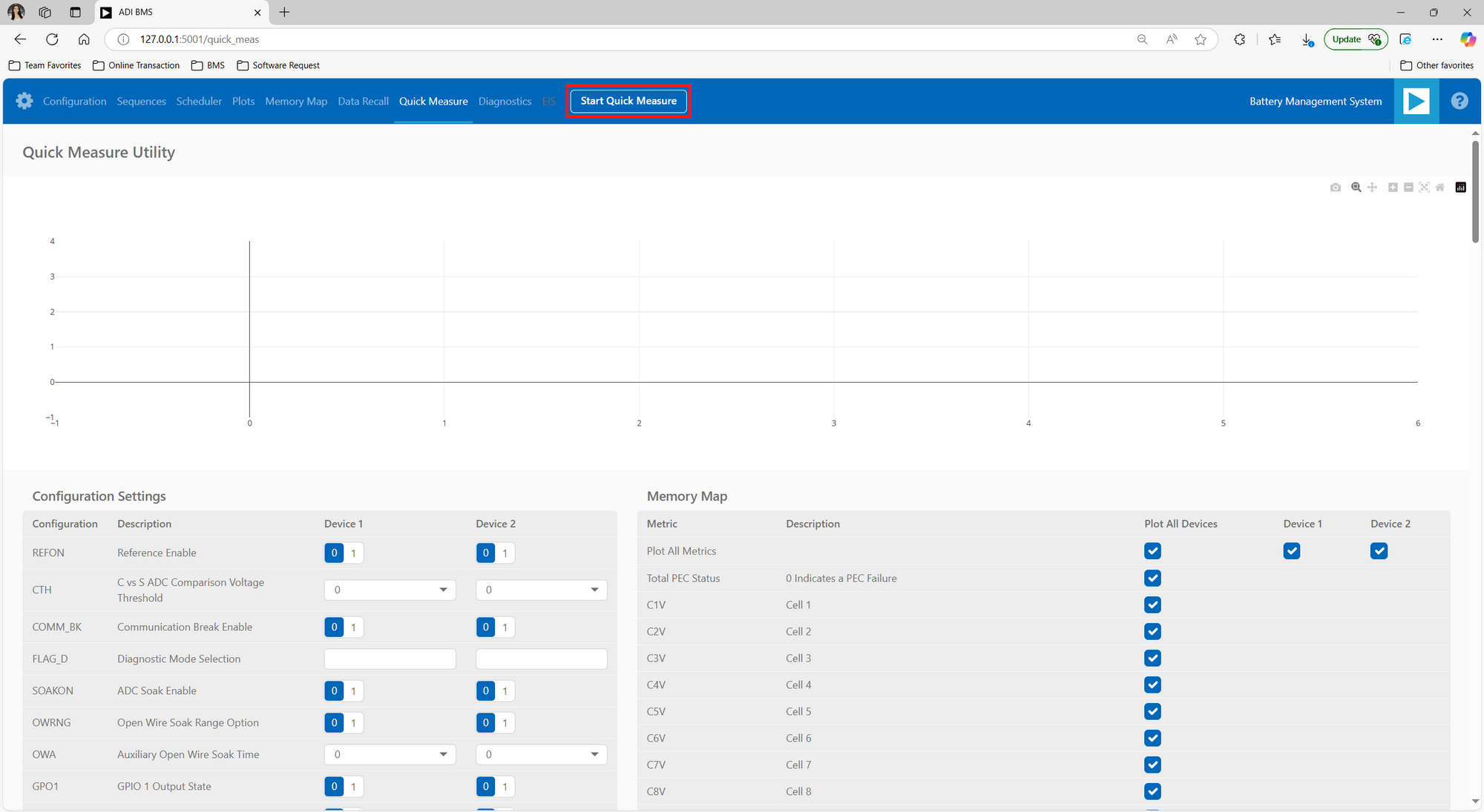
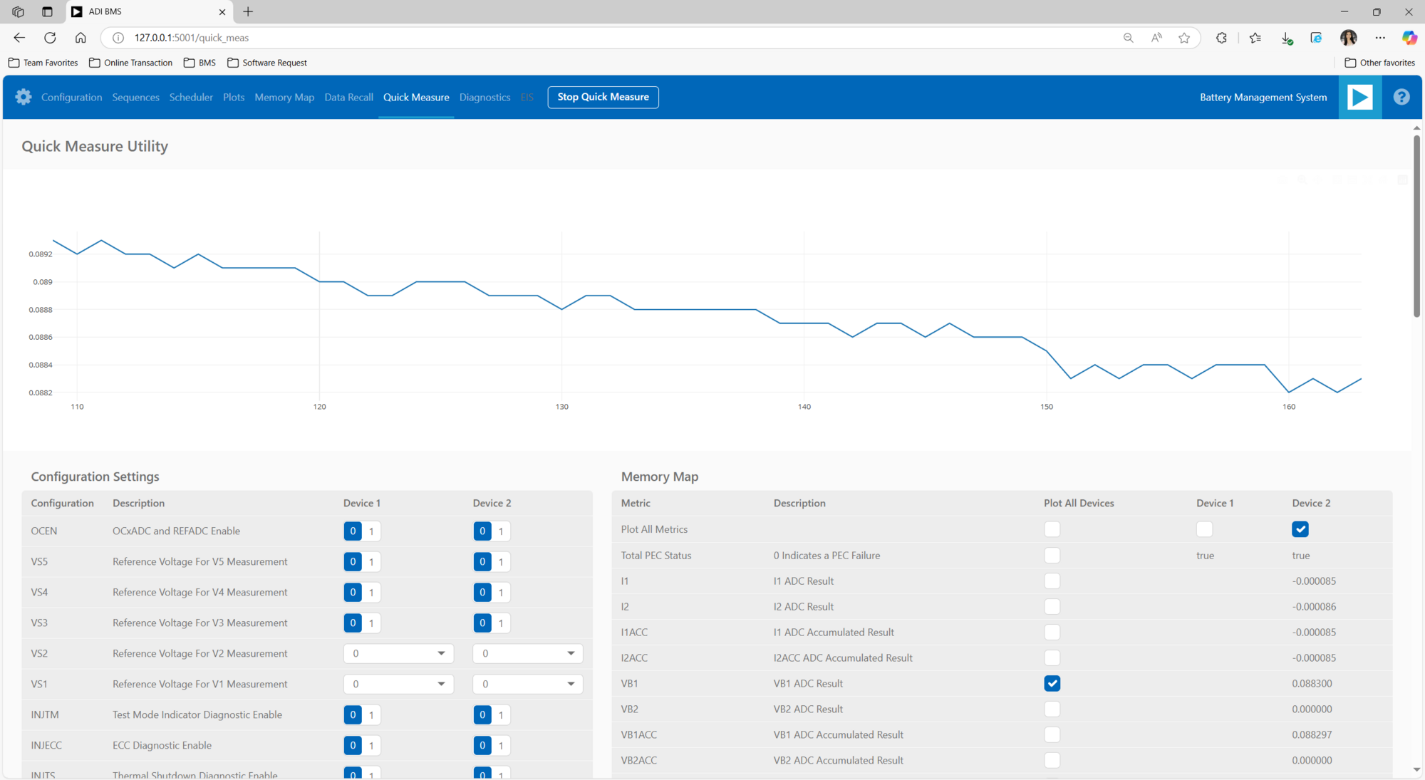
Upon launching, the Quick Measure tab will open. Note: this utility only supports a single BMS product in a Daisy Chain. Click Start Quick Measure to begin measurements.
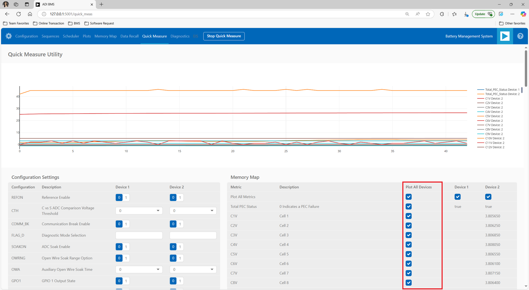
Check the Total PEC Status under the Memory Map. This indicates the status of the isoSPI link between the EVAL-ADBMS6822 and the EVAL-ADBMS6830BMSW and EVAL-ADBMS2950-BASIC.
Verify the connection of the twisted cable between the EVAL-ADBMS6822 and the EVAL-ADBMS6830BMSW.
Ensure that the EVAL-ADBMS6830BMSW and EVAL-ADBMS2950-BASIC are powered up properly.
Check the cell voltage readings. Monitor the voltage channels on the Quick Measure Utility graph. Select which signals to display on the graph under the Plot All Devices column.
Note
For Step 9: If cell voltage measurement is the focus of the demo, place ADBMS6830 as the second device in the daisy chain—both in hardware wiring and software configuration. If battery pack current and voltage monitoring is the priority, place ADBMS2950 as the second device in the daisy chain. This is important because the BMS Browser GUI primarily recognizes and interacts with the second device in the daisy chain during operation.
Results and Discussion
Quick Measure Tab
The Quick Measure tab simplifies metric measurement with a preloaded command sequence. Note that it supports a single device in the daisy chain, and key features enhance configuration and visualization.
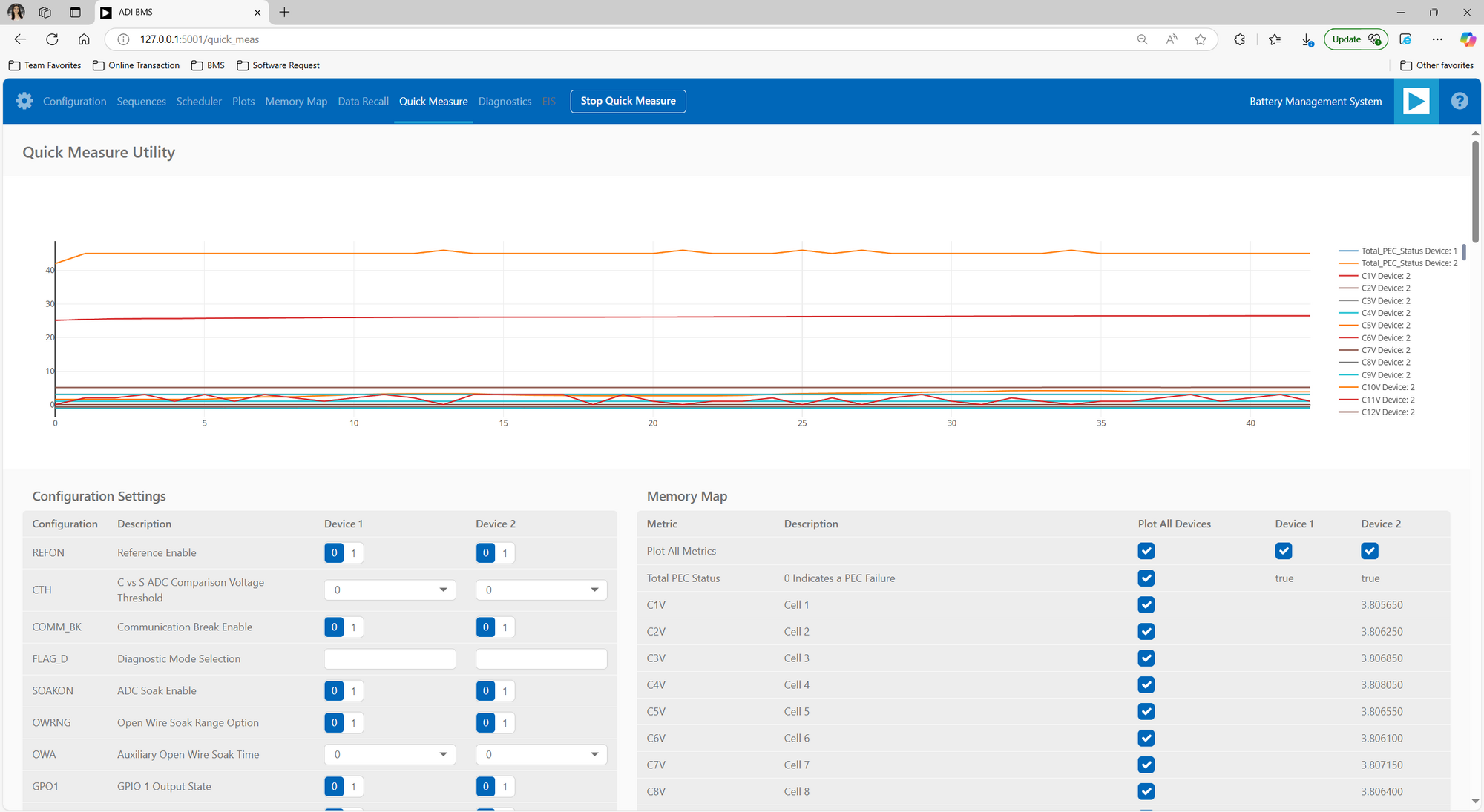
Battery Cell Voltage Monitoring
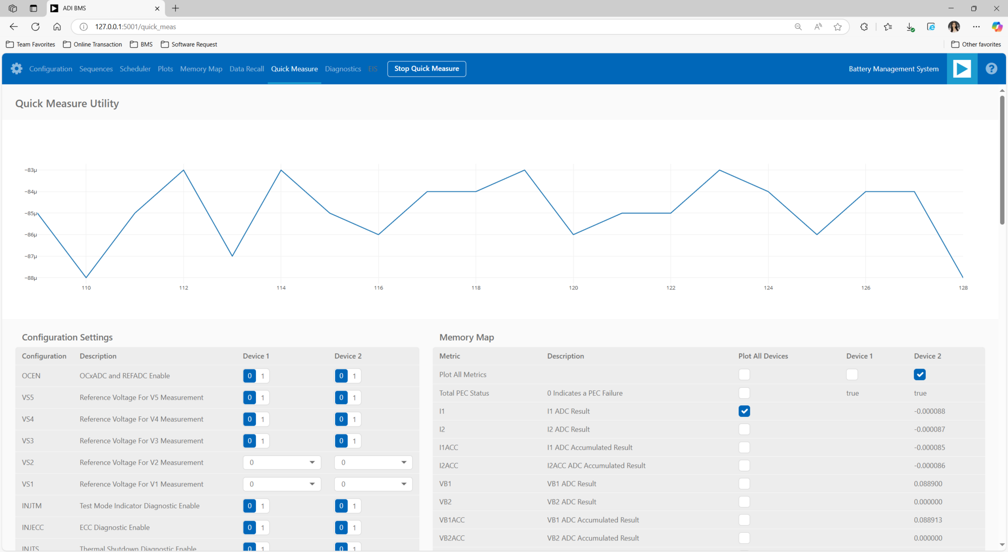
Battery Pack Current Monitoring
Using a 50μΩ shunt resistor, the total battery pack current can be calculated by dividing the I1ADC voltage by the shunt resistance. For instance, with an I1ADC voltage of 0.000088V, the current is determined as:
This calculation provides the actual current flowing through the battery pack based on the measured voltage across the shunt resistor.
Battery Pack Voltage Monitoring
ADBMS2950B features two dedicated battery-stack voltage measurements path that connect to one or two external resistor dividers via the VBAT1 and VBAT2. In this example, the battery-stack voltage is determined as:
The voltage at these pins is first buffered to provide a high input resistance and then applied to two 16-bit ADCs.
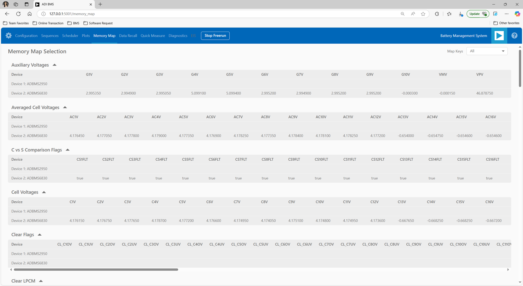
Memory Map Tab
The Memory Map tab provides a numerical output for the active command loop, organized into tables for user convenience. It offers customization and error highlighting for effective data analysis.
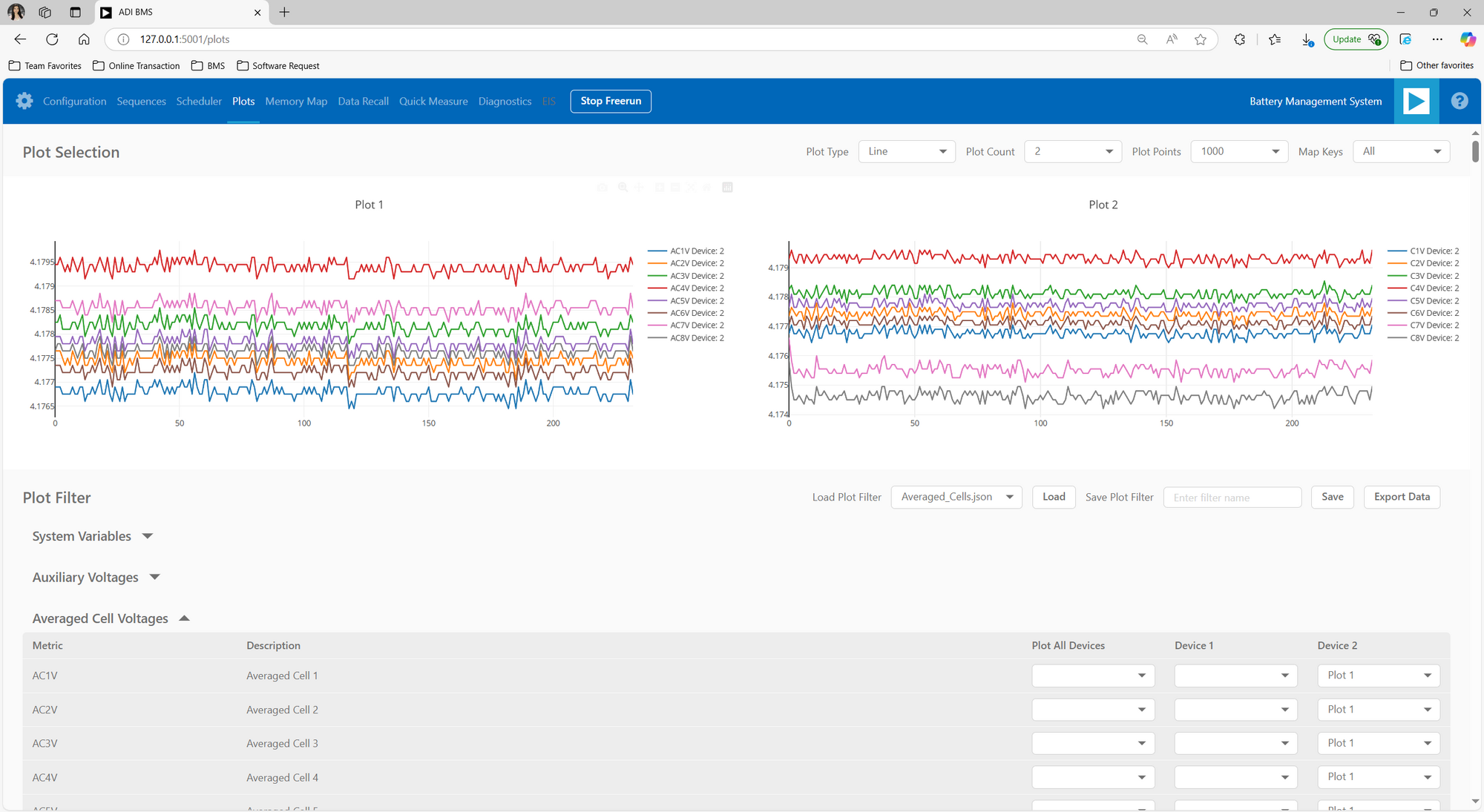
Plots Tab
The Plots tab provides a graphical representation of data collected through the running command loop. It offers customization options for focused analysis and allows for the export of captured data for further analysis.
Note
Refer to the GUI Tabs section of the
- Software User Guide for a comprehensive overview of each
tab’s functions and descriptions.
Notes
Battery and Electrical Safety
Lithium-Ion Batteries: Handle with care to prevent overcharging, deep discharging, and physical damage. Use insulation and protective gear to avoid thermal runaway.
Spot Welding: Work in a well-ventilated area and use protective equipment to avoid exposure to harmful fumes.
Resistor Load Testing: Ensure the resistor has an adequate power rating (100W) to prevent overheating.
Electrical Hazards
Secure and insulate all electrical connections to prevent short circuits.
Disconnect the battery before adjusting wiring to minimize shock risks.
Intellectual Property and Commercial Use
The design and setup detailed in this guide are intended for educational, demo, and prototyping purposes only. They are not intended for use in commercial or mass production applications.
Environmental Considerations
Dispose of lithium-ion batteries properly.
Protect components from extreme temperatures, moisture, and humidity.
Help and Support
For questions and more information, please visit the Analog Devices Engineer Zone.
For internal support, you can raise a question or submit a ticket through our Jira Service Desk using the following link: BU Applications Technical Support.
For external users, please post your questions under the Reference Designs forum in EngineerZone to get assistance from the community and experts.