IIO OSC ADRV904x Capture Window
Introduction
Main receivers RX1 through RX8 are handled by the axi-adrv904x-rx-hpc IIO
device.
Channels:
IIO device channel:
axi-adrv904x-rx-hpcReceiver inputs:
{
voltage0_i,voltage0_q}: RX1{
voltage1_i,voltage1_q}: RX2{
voltage2_i,voltage2_q}: RX3{
voltage3_i,voltage3_q}: RX4{
voltage4_i,voltage4_q}: RX5{
voltage5_i,voltage5_q}: RX6{
voltage6_i,voltage6_q}: RX7{
voltage7_i,voltage7_q}: RX8
Transmitters TX1 through TX8 are handled by the axi-adrv904x-tx-hpc IIO
device.
IIO Oscilloscope using Linux
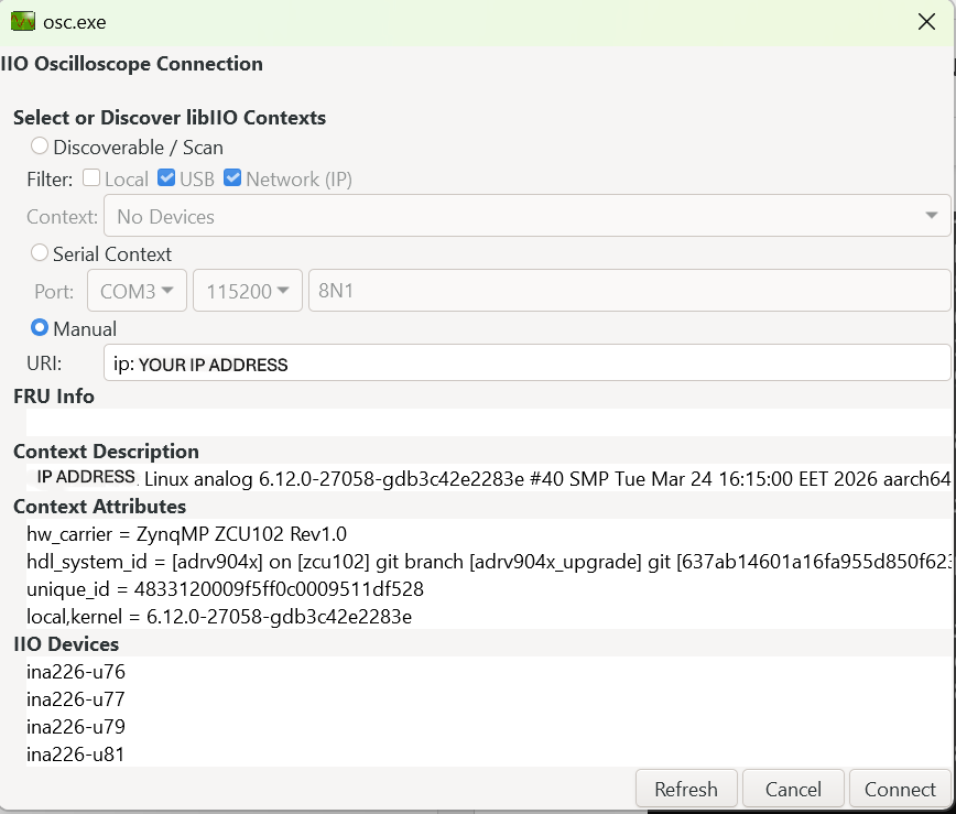
Find the board IP address using ifconfig on the serial terminal — look for
the inet address on the eth0 interface.
Enter the IP address in IIO Oscilloscope, then click Refresh and Connect:
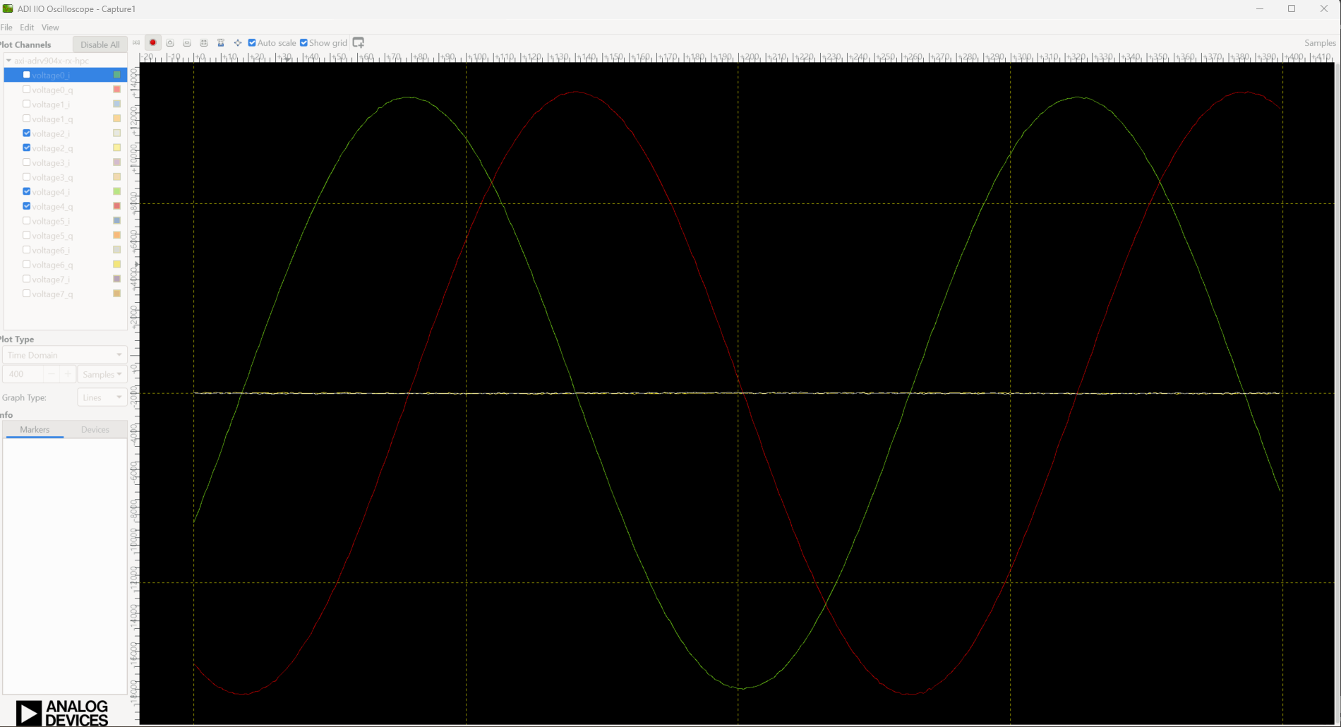
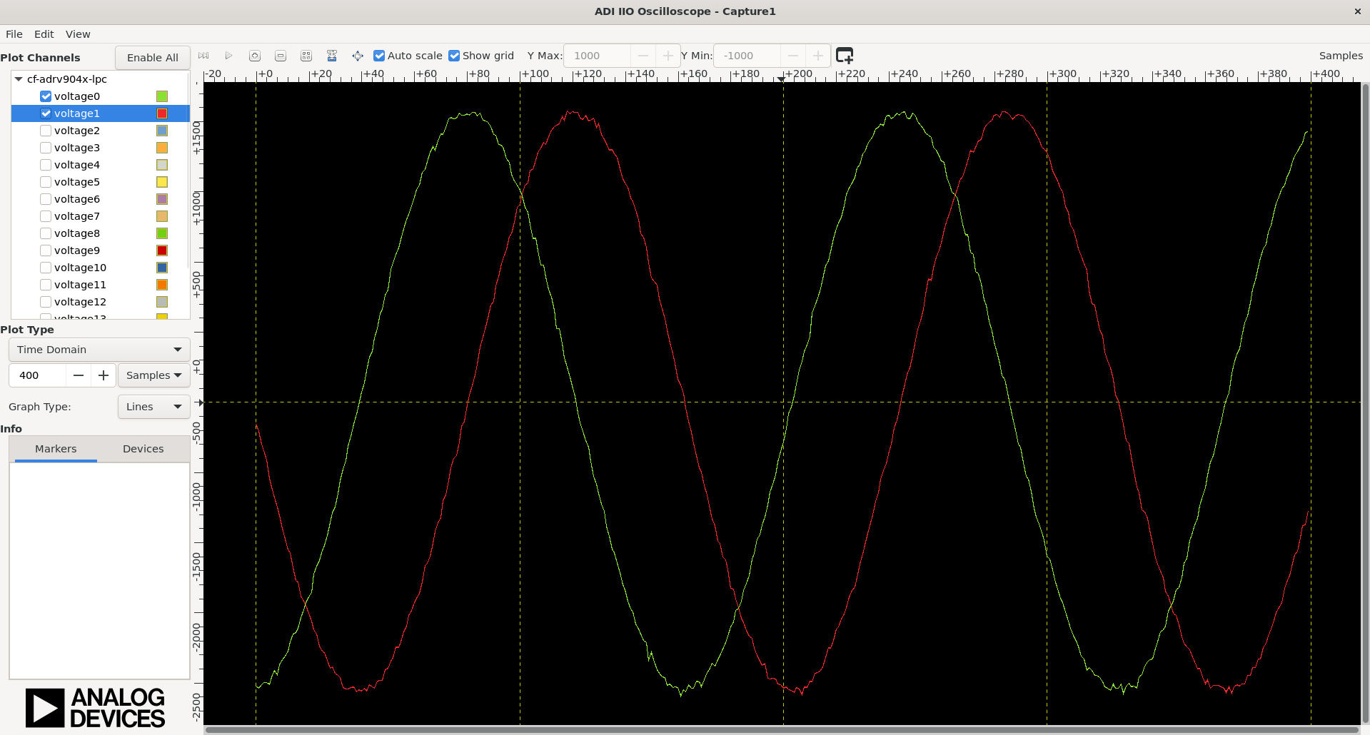
Signal visualization
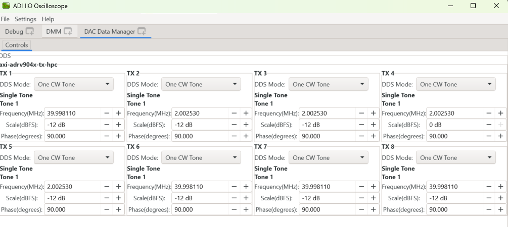
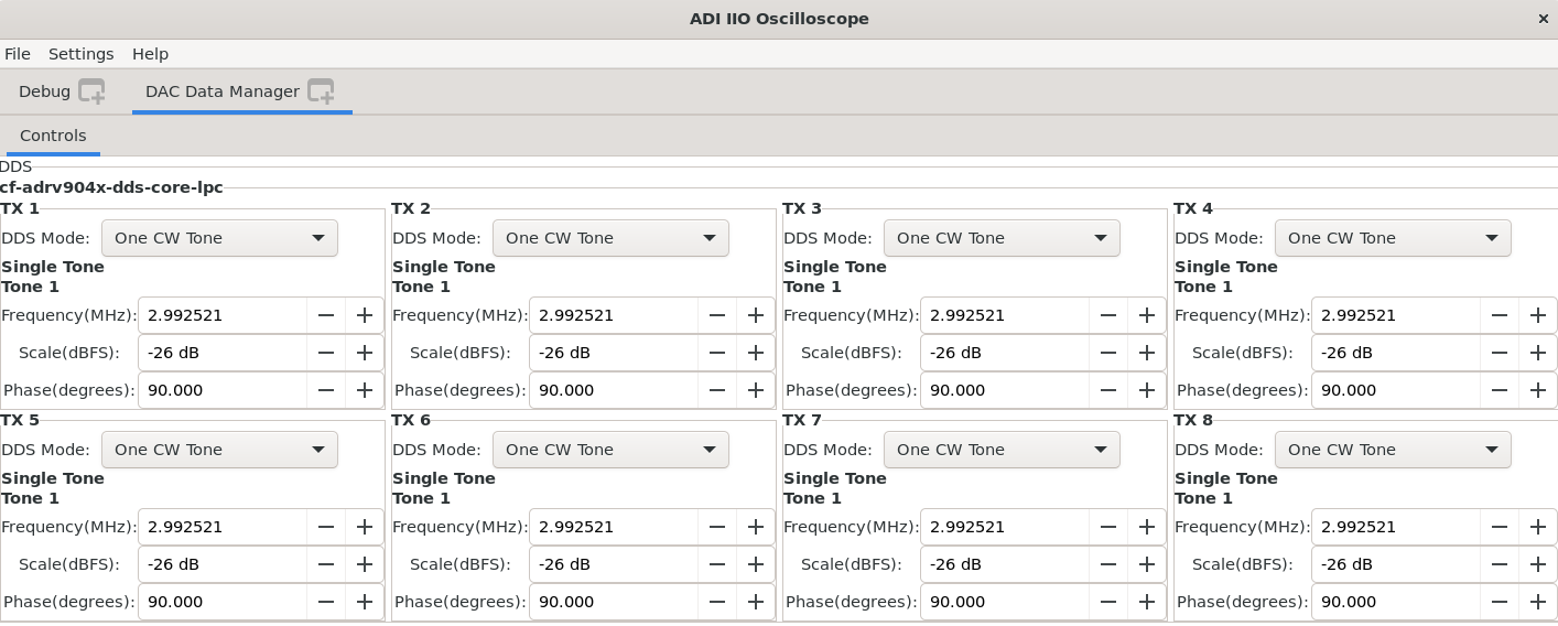
From the DAC Data Manager you can configure TX signal parameters (TX channels are mapped 0–7 on-board, displayed as 1–8 in IIO Oscilloscope; RX channels are mapped 0–7 in both environments). Select the RX channels you want to verify in the left panel and press Play:
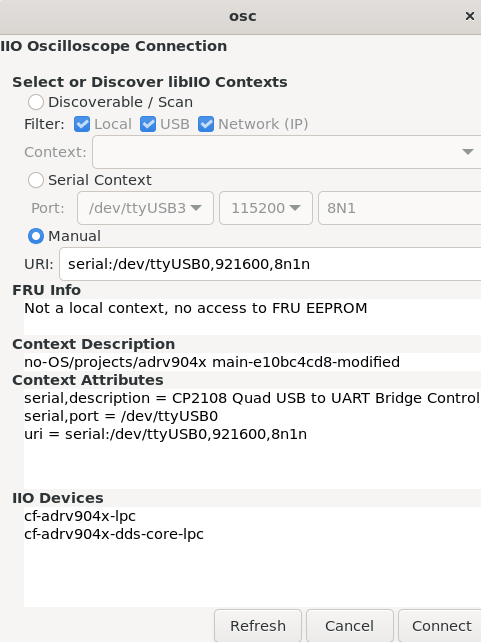
IIO Oscilloscope using no-OS
When running the IIO example, connect IIO Oscilloscope using the serial backend (select Serial in the connection dialog and configure as shown in the boot log: 921600 baud, 8N1). Then click Refresh and Connect:
From the DAC Data Manager you can configure TX signal parameters (TX channels are mapped 0–7 on-board, displayed as 1–8 in IIO Oscilloscope; RX channels are mapped 0–7 in both environments, where RX0 corresponds to Voltage 0 and 1, RX1 to Voltage 2 and 3, and so on):
About the IIO devices
NLS profile (with observation receiver)
When using the NLS device tree (zynqmp-zcu102-rev10-adrv904x-nls.dts), the
observation receiver path is enabled. The observation receiver IIO device
appears as an additional device:
~$
iio_info | grep iio:device
iio:device0: xilinx-ams
iio:device1: adrv904x-phy
iio:device2: axi-adrv904x-rx-hpc (buffer capable)
iio:device3: axi-adrv904x-tx-hpc (buffer capable)
iio:device4: axi-adrv904x-obs-hpc (buffer capable)
To use the NLS profile, copy system.dtb built from
zynqmp-zcu102-rev10-adrv904x-nls.dts and DeviceProfileTest_NLS.bin
renamed to DeviceProfileTest.bin to the SD card boot partition.
Scopy
Scopy is a cross-platform software toolbox for interfacing with ADI devices, enabling you to configure device parameters, visualize data, and perform advanced signal analysis.