Tuning the AD9361/AD9364
Theory
Applications such as wireless base stations (BTS) require that the reference clock lock to a system master clock. In these situations, it’s recommended to use a stable external oscillator such as a VCTCXO [1] in conjunction with a synchronizing PLL such as the AD9548, which can be sync’ed to a 1 PPS [2] output from a GPS chipset. This will give you the most stable time base possible, and meet the requirements of base stations.
Wireless user equipment (UE), however, does not typically need to be locked to a master clock but they do need to adjust the LO frequency periodically to maintain connection with a base station. The BTS typically occasionally informs the UE of its frequency error relative to the BTS. This will help account for any sorts of frequency error, including temperature, or stability issues of low cost crystals and Doppler shift due to movement between the UE and the BTS.
To solve the UE problem with crystals, the AD936x includes a digitally controlled adjustable trimming capacitor inside the crystal oscillator tank circuit on the XTALP pin. The baseband processor can adjust the reference clock frequency by adjusting this capacitor. This combination of external crystal (XO) and trimming capacitor is collectively referred to as the digitally controlled external crystal (DCXO).
To solve the UE problem with oscillators, (which drive into XTALN single ended, and are not affected by external capacitance), the above tuning solution will not work. The only solution for this is to read the actual oscillator frequency, and tell the system that actual frequency.
Frequency errors are something that is going to change with each specific crystal/oscillator. It’s not something where the settings on one board/AD936x/crystal combination will work on a different board/AD936x/crystal combination.
Impact
When discussing parts per million (or ppm) stability issues - the size of the actual impact is sometimes lost.
The 40 MHz crystal on the FMCOMMS2/3/4 is an Epson special for Analog Devices (it’s a TSX-3225, with reduced jitter, which in this application is more important than absolute accuracy datasheet). It has a spec of initial frequency tolerance of +/-10.0 ppm, frequency stability (temp co) of +/-15.0 ppm max, and an aging spec of +/-2.0 ppm. This works out to an RMS average (including aging) of +/-18.1 ppm. (we do an RMS, since it’s statistically unlikely that all deviations would be the max at the same time).
This ppm specification indicates how much the crystal frequency may deviate from the nominal value. +/-10 ppm is +/-0.001%, 18.1 ppm is 0.00181%. For a 40.000000 MHz crystal, that means 39.99928 to 40.00072 MHz. When this is multiplied up in the baseband PLL and then decimated down this can mean rather than a nominal output data rate of 30.72 MSamples per second, it can be anywhere between 30.72055296 and 30.71944704 MSamples per second, and a 2.400000000 GHz nominal center frequency might be anywhere between 2.4000432 and 2.3999568 GHz. That’s a frequency offset of +/-43.2 kHz.
Luckily, most receive algorithms include some sort of coarse and fine frequency correction to fix the LO, but they need to understand that:
the coarse correction/compensation needs to correct for ppm issues (which scale with LO, the higher the LO, the higher the possible frequency offset).
the sample rates will also be off the same amount
Crystals are available in different precisions, +/-10 ppm less, you’ll pay more. It’s always a tradeoff between jitter, precision, power and price. For the FMCOMMS2/3/4 solutions, ADI decided to sacrifice precision for price - to demonstrate that the AD9361 can be used with a low cost crystal solution. Because of this the FMCOMMS2/3/4 boards are not meant to be used for BTS type applications, where absolute actual frequency is required.
External Crystals
This section describes the setup, operation, and recommended specification of the DCXO [3] and reference clock used on the FMCOMMS2/3/4 and ARRADIO platforms. This technique can not be used on FMCOMMS5 or PicoZed SDR, which uses a single ended oscillator, not a crystal.
By adjusting a capacitor within the AD9361, the resulting DCXO frequency can be adjusted to compensate for XO frequency tolerance and stability. The resolution of the DCXO varies with coarse word with a worst-case resolution (at coarse word = 0) of 0.0125 ppm. Using both coarse and fine words, the DCXO can vary the frequency over a +/-60 ppm range.
Using a bench test, nominal DCXO trimming words should be determined and then used during initialization. These nominal words should be written before the BBPLL is calibrated. After initialization (after the BBPLL and RFPLLs are programmed, calibrated, and locked), the DCXO words may be written at any time.
Practice
To tune the AD9361, you need to determine how you want to tune things:
manually
automatically
and you need to decide what you want to tune:
RF input or output
internal ADC clock
or buffered crystal
The decision of what/how can come down to, what equipment do I have in the lab, or production test station, and how much time it takes, and is the software written to take advantage of things.
The suggested/preferred way to tune things today is automatically, measuring the buffered crystal output. To measure the frequency, we have used either Hameg HM8123 or the Agilent 53131A frequency counters, and the SCPI code inside the osc application supports this.
Other methods will be described as well.
Determining outputs to measure
To observe the internal clocks, or crystal, this is controlled by the CLOCKOUT settings of the Advanced tab of the IIO Scope.

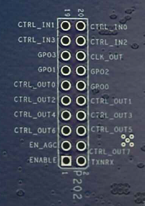
This will control the CLK_OUT pin on the AD9361, which can be found on the
P202 pin header of the FMCOMMS2/3/4 boards. Other boards may vary. It is
necessary to be able to observe this output with a frequency counter, or
something that will tell you the frequency to do the tuning.
To observe the RF output, look at the output. You will need to make sure to look at both the RF carrier and any signal (the DDS) that is on the output.
Manual settings
There is no automated process to do this, since this isn’t going to be very accurate, and is not recommended, but it is possible to use an oscilloscope to measure the frequency of the CLOCKOUT pin, or a spectrum analyzer of the RF output.
It’s just a matter of manually changing the DCXO coarse and fine tuning until you get the result you want, and then clicking “Save to EEPROM”.
Automated tuning
With the latest version of IIO Oscilloscope it’s possible to run an automated tuning process via a SCPI -connected device (currently either the HM8123 or 53131A listed above).
This support is provided in the FMComms2/3/4 plugin as seen below.

Currently only two calibration methods are supported, REFCLK and RF Output. In
order to use the REFCLK option the signal from the CLK_OUT pin described
above must be used as input for one of the supported counters.
Using the RF Output method requires connecting TX1 from the FMComms card to the input of a counter.
Note that the method providing the most accurate end result should be REFCLK.
Process
Turn on the counter and make sure it’s connected via USB to the system that will be running IIO Oscilloscope; performing the process on the system with the FMComms card connected is easiest. In addition, make sure the correct signal output from the FMComms card is connected to the first input channel on the frequency counter as described above.
Force the SCPI plugin to be loaded before running osc as root by launching a terminal and running the following:
root@analog:~# sudo su
root@analog:~# export OSC_FORCE_PLUGIN=scpi
root@analog:~# osc
Select from the calibration methods described previously and hit the ‘Calibrate DCXO’ button on osc.
A calibration progress bar should appear as seen below if everything is properly connected and the process is proceeding. If not an error message should pop up, noting what probably went wrong. Usually errors come from using a mismatched calibration method with input to the counter device or SCPI connection issues. In addition, note that a calibration in progress can be cancelled by hitting the ‘Stop calibration’ button also seen in the image below.
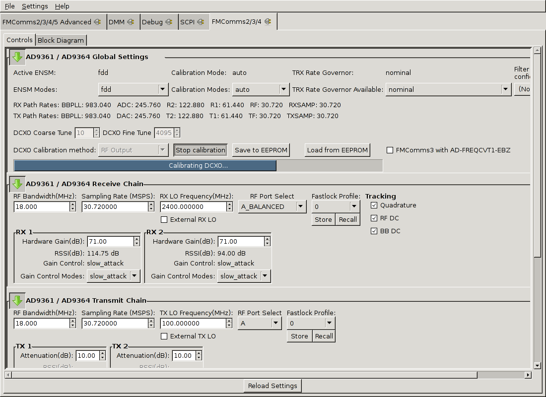
As the process proceeds, you should see the coarse and fine tune parameters being changed as the search narrows in on the most accurate values for the parameters in relation to the selected calibration method. In particular, the process sets the fine tune parameter to half its max possible value and then increases the coarse tune parameter until doing so would cause the output to go past the target frequency. Then the same process is done with the fine tune parameter until the closest value is found. If some issue occurs and the tuning parameters exceed the allowed bounds an error should be shown. Often this means the wrong calibration method was selected as mentioned previously.
Using an RF Source
A future planned extension to this work is calibrating against an RF Input source in which an antenna would be attached and the user would select a known frequency being used for a local broadcast or similar (e.g. an FM radio station) that would then be tuned against.
Oscillators
This technique can be used on FMCOMMS5, PicoZed SDR, or the Pluto SDR, which uses a single ended oscillator, not a crystal.
This is normally done by two methods:
measuring the CLK_OUT (similar to the above)
measuring a known RF signal (Fsig)
The issue with measuring a known RF signal is that both the sample rate (FS) and local oscillator (FLO) are affected by the oscillator offset.
It’s easier to understand things by working through an example. If we simplify the concept of the AD9361 clock tree, VCOs and PLLs; we can assume that it is just a simple multiply between the oscillator frequency (FOSC) and both the Rx local oscillator (FLO) and ADC sample rate (FS).
\(F_LO = F_OSC \times MULT_LO\)
\(F_S = F_OSC \times MULT_FS\)
If we have an Oscillator Frequency (FOSC) of 40.0 MHz; an Rx local oscillator (FLO) of 2400 MHz (MULTLO=60), and an ADC sample rate (FS) of 7.68 MSPS (MULTFS=0.192), this is what we would expect to see:
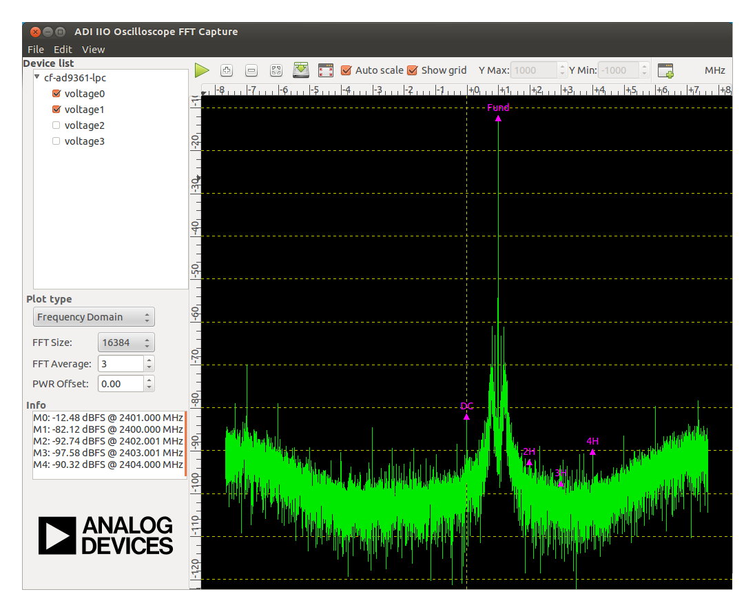
With an FFT size of 16384, the size of each bin is \(F_S / 16384\), or in this case, \(7.68 MHz / 16384\) or 468.75 Hz/bin. In this case, the 1 MHz offset would be in the bin 2133 (from centre).
However, if we have a (for example +10 ppm offset), the numbers work out to something like:
FOSC = 40.000000 * 1.00001 = 40.0004 MHz
FLO = 40.0004 MHz * 60 = 2400.024 MHz
FS = 40.0004 MHz * 0.192 = 7.6800768 MSPS
FFT bin size (for 16384 samples) = 7.6800768 MHz / 16384 = 468.75046875 Hz/bin
A 2401.000000 MHz CW tone shows up as a (2401.0000 MHz - 2400.024 MHz) = 0.976 MHz offset, or in the 2081 bin (based on 468.796875 Hz/bin), however, it would be reported as 0.97546875 MHz offset (due to the application thinking it is 40.00000000 MHz, and using 468.75 Hz/bin; and would be reported as 2400.9759902401 MHz, which is a 10.21 ppm error.
Working backwards is possible. If you trust the external signal more than the internal oscillator (FOSC), you should use this method.
Measurement of 2401.03601554023 MHz, while the actual signal is 2401.0000000 MHz, means you are off -15 ppm (or the FOSC should be set to 39.999400 MHz). To calculate this, it’s just a little simple algebra.
\(\mathrm{PPM} = 1 + \mathrm{error} / 10^6\)
\(F_{\mathrm{LO}} = (F_{\mathrm{OSC}} \cdot \mathrm{PPM}) \cdot \mathrm{MULT}_{\mathrm{LO}}\)
\(F_{S} = (F_{\mathrm{OSC}} \cdot \mathrm{PPM}) \cdot \mathrm{MULT}_{\mathrm{FS}}\)
\(F_{\mathrm{READING}} = F_{\mathrm{ACTUAL}} - F_{\mathrm{LO}}\)
\(\mathrm{bin} = (F_{\mathrm{READING}} \cdot N_{\mathrm{bins}}) / F_{S}\)
substitution provides:
\(\mathrm{bin} = (F_{\mathrm{ACTUAL}} \cdot N_{\mathrm{bins}} - F_{\mathrm{OSC}} \cdot \mathrm{PPM} \cdot \mathrm{MULT}_{\mathrm{LO}} \cdot N_{\mathrm{bins}}) / (F_{\mathrm{OSC}} \cdot \mathrm{PPM} \cdot \mathrm{MULT}_{\mathrm{FS}})\)
and this provides:
\(\mathrm{PPM} = (F_{\mathrm{ACTUAL}} \cdot N_{\mathrm{bins}}) / (F_{\mathrm{OSC}} \cdot (\mathrm{MULT}_{\mathrm{FS}} \cdot \mathrm{bin} + \mathrm{MULT}_{\mathrm{LO}} \cdot N_{\mathrm{bins}}))\)
since everything is a known, but PPM, it can be solved by simple substitution. You can also see from that that lots of bins are good, and things that are away from the LO (have a large bin number) will provide more detail to work on. The actual frequency shouldn’t really matter that much, and tuning things at 500 MHz, should be similar to tuning things at an LO of 3500 MHz.
In this example, we:
send 2401.0000 MHz tone,
think we have a 40.000 MHz oscillator (which we know is wrong)
set the LO to 2400 MHz, (have a MULTLOof 60)
set the sample rate to 7.68 MSPS (have a MULTFSof 0.192)
do a 16384 point FFT,
read the peak of the FFT at bin number 2210.166486
\(PPM = 2401.0000000 MHz \times 16384/{40.0000000 MHz} \times (0.192 \times 2210.166486 + 60 \times 16384)\)
\(PPM = 39337984 / 39338574.07861248 = 0.999985 = (1 - 0.000015) = -15ppm\)
The more accurate the bin number, the more accurate the ppm offset result will
be. You may think a bin number of 2210.166486 is contrived - however, it is
very easy to actually measure that using Quadratic Interpolation of Spectral
Peaks
to find the actual peak and where it is expected to be in the fractional part of
the bin. The three closest peaks fit a parabola (which is a good approximation
for narrow CW Tones which have had their energy spread into adjacent bins by a
FFT window function), and the actual peak is found.
Once we find the offset in terms of ppm, it is a quick matter of programming the system with the correct oscillator value. In the case of -15 ppm offset, that would be 39.999400 MHz, or a value of 39,999,400 Hz to be used to set the value in XO Correction.
This specifies any shell prompt running on the target
C:\Users\rgetz>iio_attr -a -d * xo_correction
Using auto-detected IIO context at URI "usb:1.6.5"
dev 'ad9361-phy', attr 'xo_correction', value :'40000000'
Pluto SDR
To make this easier for ADALM-PLUTO users, the cal_ad9361 application was created, which is found on your PlutoSDR. All you need to do is find a strong tone (like an ATSC pilot tone), and use that to tune the radio.
This specifies any shell prompt running on the PlutoSDR
login as: root
root@192.168.2.1's password: analog
Welcome to:
%%______ _       _        _________________
| ___ \ |     | |      /  ___|  _  \ ___ \ |
| |_/ / |_   _| |_ ___ \ `--.| | | | |_/ / |
|  __/| | | | | __/ _ \ `--. \ | | |    / |
| |   | | |_| | || (_) /\__/ / |/ /| |\ \ |
\_|   |_|\__,_|\__\___/\____/|___/ \_| \_|
%%
v0.31-dirty
http:%%//%%wiki.analog.com/university/tools/pluto
# cal_ad9361
Practical considerations
In the above examples, if you do not account for ADC sample rate offset, you will never be able to get an exact reading, but it might be close enough. For example, if we take the previous example:
In this example, we:
send 2401.0000 MHz tone,
think we have a 40.000 MHz oscillator (which we know is wrong)
set the LO to 2400 MHz, (have a \(MULT_LO\) of 60)
set the sample rate to 7.68 MSPS (have a \(MULT_FS\) of 0.192)
do a 16384 point FFT,
read the peak of the FFT at bin number 2210.166486
And only worry about LO offset, we think the FFT is at 1036015.54 Hz offset from the LO (since we don’t correct for 7.68 MHz being wrong), and that the actual LO is 36015.54031 Hz off (which gives us a simple -15.0064751302 ppm); and we set the XO correction to 39999399 (which is a small error, but still wrong).
In most practical examples, it would be fine to ignore this when the sampling rate to RF LO frequency is high (in this case 2400:7.68 or 312.5:1). When LOs are low, and sample rates increase, it creates a larger impact, and can’t be ignored.