Introduction to boards based on the AD9361/AD9363/AD9364


Overview
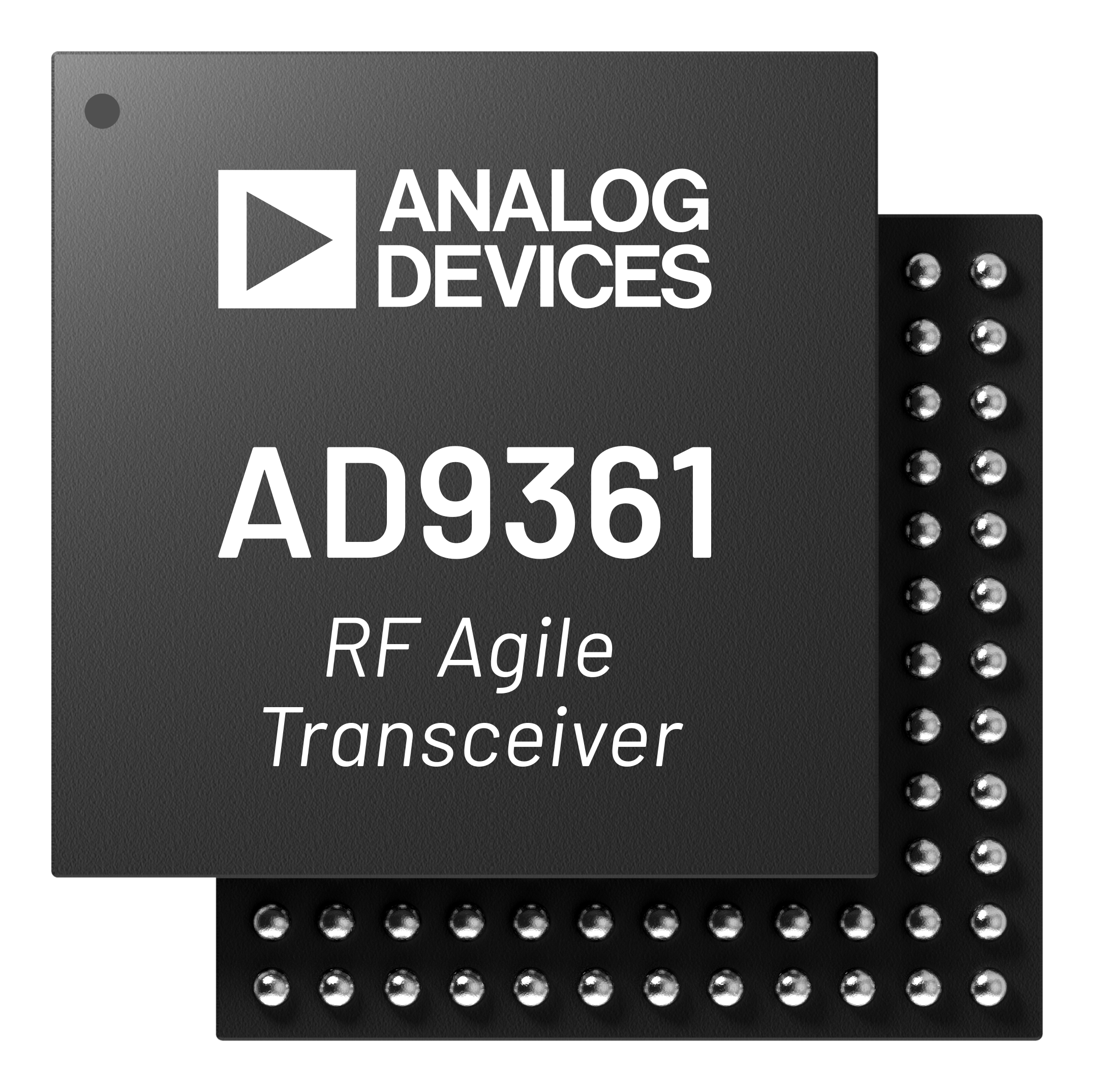
The AD-FMCOMMS[2345]-EBZ and ARRADIO cards are high-speed analog modules designed to showcase the AD9361 or AD9364, a high performance, highly integrated RF agile transceiver intended for use in RF applications, such as 3G and 4G base station applications and software defined radios. Its programmability and wideband capability make it ideal for a broad range of transceiver applications. The device combines an RF front end with a flexible mixed-signal baseband section and integrated frequency synthesizers, simplifying design-in by providing a configurable digital interface to a processor or FPGA. The AD9361 and AD9364 operate in the 70 MHz to 6 GHz range, covering most licensed and unlicensed bands. The boards, due to discrete external components, may have less performance on some of the RF input/output connectors (for example - the FMCOMMS2 and specific connectors on the FMCOMMS5 are specifically tuned to 2.4 GHz). The AD9361 and AD9364 both support channel bandwidths from less than 200 kHz to 56 MHz by both changing sample rate, and by changing digital filters and decimation inside the device itself.
The difference between the AD9361 (2 Rx, 2 Tx) and AD9364 (1 Rx, 1 Tx) is the number of channels. Software, HDL, pinout, etc - is all exactly the same.
Applications
Wireless communications demonstration and learning tool
Remote radio head
Software-defined radio
Satellite modems
Test and measurement equipment
Radar and advanced imaging
General purpose data acquisition
Specifications & Features
General purpose design suitable for any application
Software tunable across wide frequency range (70 MHz to 6 GHz)
Less than 200 kHz to 56 MHz channel bandwidth
Powered from single FMC connector
Supports MIMO radio, with less than 1 sample sync on both ADC and DAC
Includes schematics, layout, BOM, HDL, Linux drivers and application software
Supports add on cards for spectrum specific designs (PA, LNA etc)
AD-FREQCVT1-EBZ is frequency up and down conversion to allow the AD9361 to operate down to 1 MHz.
AD-TRXBOOST1-EBZ is to add a pre-amp to the TX output and an LNA to the RX input of the AD9361.
SPI access for all device registers
Available Hardware
Standalone Platform
Board |
AD936x Device |
Simultaneous Tx / Rx |
Tx (Ranges) |
Rx (Ranges) |
Purpose |
|---|---|---|---|---|---|
1 x AD9363 |
1 x 1 |
1 (325 - 3800 MHz) |
1 (325 - 3800 MHz) |
Active Learning Module |
The ADALM-PLUTO is just the AD9363 in a 1 x 1 RF configuration with on-board Z7010 FPGA. PlutoSDR is a self contained RF lab in your hand, powered through USB. The board includes a narrow tuning range balun, which is performance optimized for 2.4 GHz. It is a stand alone unit requiring only USB for power and communications; it does not connect to a carrier board.
FMC/HSMC Evaluation Boards
Board |
AD936x Device |
Simultaneous Tx / Rx |
Tx (Ranges) |
Rx (Ranges) |
Purpose |
Connector |
|---|---|---|---|---|---|---|
1 x AD9361 |
2 x 2 |
2 (2400 - 2500 MHz) |
2 (2400 - 2500 MHz) |
Best RF performance in a narrow range |
HSMC |
|
1 x AD9361 |
2 x 2 |
2 (2400 - 2500 MHz) |
2 (2400 - 2500 MHz) |
Best RF performance in a narrow range |
FMC-LPC |
|
1 x AD9361 |
2 x 2 |
2 (70 - 6000 MHz) |
2 (70 - 6000 MHz) |
Software test and waveform development |
FMC-LPC |
|
1 x AD9364 |
1 x 1 |
1 (2400 - 2500 MHz), 1 (70 - 6000 MHz) |
1 (2400 - 2500 MHz), 1 (70 - 6000 MHz) |
FMC-LPC |
||
2 x AD9361 |
4 x 4 |
4 (2400 - 2500 MHz), 4 (70 - 6000 MHz) |
4 (2400 - 2500 MHz), 4 (70 - 6000 MHz) |
MIMO test platform, can be synchronized in the RF domain |
2 x FMC-LPC |
These evaluation boards connect to FPGA carrier boards through FMC or HSMC connectors.
Important
While the AD9361 digital interface supports both LVDS and CMOS mode, all the FMCOMMS boards have been verified in LVDS mode only. Configuring the digital interface in CMOS mode is not tested nor supported on these platforms. This is due to the purposefully weak CMOS drivers (to keep the noise off the part as much as possible) that are part of the digital interface and the large capacitance of the FMC connector.
If you configure any board to work in CMOS mode, and it does not, this is expected. If it does work, it just means the combination of AD9361 board, AD9361, connectors, carrier layout and FPGA are barely working.
CMOS mode is known to work on platforms without connectors between the AD936x and the Digital BaseBand device (like PicoZed SDR).
System on Modules (SOMs)
Board |
AD936x Device |
Simultaneous Tx / Rx |
Tx (Ranges) |
Rx (Ranges) |
Purpose |
|---|---|---|---|---|---|
1 x AD9364 |
1 x 1 |
1 (2400 - 2500 MHz) |
1 (2400 - 2500 MHz) |
Highly Integrated System on Module |
|
1 x AD9361 |
2 x 2 |
2 (2400 - 2500 MHz) |
2 (2400 - 2500 MHz) |
Highly Integrated System on Module |
These SOMs integrate the AD936x transceiver with a Zynq FPGA on a single module, and connect to dedicated SOM carrier boards.
A detailed list of things that can be done with these boards can be found in each board page:
The ARRADIO board, in simple terms, is just the AD9361 in a 2 x 2 RF configuration. Hence the features and capabilities of the device extend to the board. The board includes a narrow tuning range balun, which is performance optimized for 2.4 GHz, and provides datasheet specifications. If you want a different range, you can change baluns (footprint compatible options are available). This board has an HSMC connector.
The AD-FMCOMMS2-EBZ board, in simple terms, is just the AD9361 in a 2 x 2 RF configuration. Hence the features and capabilities of the device extend to the board. The board includes a narrow tuning range balun, which is performance optimized for 2.4 GHz, and provides datasheet specifications. If you want a different range, you can change baluns (footprint compatible options are available). This board has an FMC connector.
The AD-FMCOMMS3-EBZ board, in simple terms, is just the AD9361 in a 2 x 2 RF configuration. Hence the features and capabilities of the device extend to the board. The board includes a wide tuning range RF transformer, which is close to datasheet specifications, but may not meet all specs over the entire 70 - 6000 MHz RF range.
The AD-FMCOMMS4-EBZ board, in simple terms, is just the AD9364 in a 1 x 1 RF configuration. Hence the features and capabilities of the device extend to the board. The board includes both a narrow and wide tuning range balun on a multiplexed input/output.
The AD-FMCOMMS5-EBZ board, in simple terms, is two AD9361s in a 4 x 4 RF configuration, which demonstrates how to synchronize multiple devices together. The features and capabilities of the device extend to the board. The board includes both narrow and wide tuning range baluns on different SMA connectors.
The ADRV9364-Z7020 board, in simple terms, is just the AD9364 in a 1 x 1 RF configuration with on-board Z7020 FPGA. Hence the features and capabilities of the device extend to the board. The board includes a narrow tuning range balun, which is performance optimized for 2.4 GHz. If you want a different range, you can change baluns (footprint compatible options are available). This board has four FCI 0.8mm connectors.
The ADRV9361-Z7035 board, in simple terms, is just the AD9361 in a 2 x 2 RF configuration with on-board Z7035 FPGA. Hence the features and capabilities of the device extend to the board. The board includes a narrow tuning range balun, which is performance optimized for 2.4 GHz. If you want a different range, you can change baluns (footprint compatible options are available). This board has four FCI 0.8mm connectors.
Carrier Boards
SOM Carrier Boards
The following carrier boards are compatible with the ADRV9364-Z7020 and ADRV9361-Z7035 System on Modules:
Carrier Board |
ADRV9364-Z7020 |
ADRV9361-Z7035 |
|---|---|---|
Yes |
Yes |
|
Yes |
Yes |
|
Yes |
Yes |
|
Yes |
Yes |
FPGA Carrier Boards
The following FPGA development boards can be used as carriers for the FMC/HSMC evaluation boards:
Legend
*removed; last release that supports this project on this carrier is hdl_2023_r2 hdl_2023_r2
Getting started
The items needed to get started are detailed in the prerequisites, and the quickstart. They detail supported carriers, external equipment requirements and how to set the boot switches.
Once you have a working platform, you may be interested in investigating:
Introduction to the AD9361/AD9364
Tuning the AD9361/AD9364 FIR Filters for your application
How to simulate the part with MathWorks RF Blockset (formerly SimRF), to see if it is appropriate for your application
Measuring actual RF performance, either with the IIO Oscilloscope, or with test equipment
How the part performs in specific algorithms, streaming data to MATLAB, Simulink, or GNU Radio
How the Linux or no-OS driver works, or can be integrated into your system
Create your own custom HDL from Simulink and insert it into the ADI design to see how it works
Modifying the ADI provided HDL
Tuning other parameters, like AGC for your application/waveform
Review a real world example using the part (ADS-B) Part 1, Part 2, Part 3 and Part 4
Look at FMCOMMS2, FMCOMMS3, FMCOMMS4, FMCOMMS5 schematics and layout to see how to get the best performance in your hardware design.