ADS-B Airplane Tracking Tutorial (Obsolete)
Warning
This model is considered deprecated. See updated model here: HW/SW Co-Design Implementation of ADS-B Receiver Using Analog Devices AD9361/AD9364.
Overview
Due to the complexity of the SDR systems nowadays, there is a significant gap between the concept of a SDR system and the realization of that working design. Bridging this gap typically involves teams of engineers with a variety of different skill sets (RF, DSP, FPGA, software, system integration and etc.), and in many cases projects get de-railed early in the development stage because of difficulty in coordinating the efforts of these varied design entities.
In this tutorial, we will present how model based design provides a collaborative solution for SDR, which allows developers of different backgrounds (RF, DSP, FPGA, software, system integration and etc.) to work together in a single environment, and quickly build and prototype SDR systems while establishing and maintaining a deployable path to production. As a real-world and interesting example of the process, we will actually build a wireless SDR platform that receives and decodes Automatic Dependent Surveillance-Broadcast (ADS-B) signals to allow us to detect and report the position, altitude, and velocity of the commercial aircraft flying in our vicinity.
The signal processing requirements of ADS-B are quite trivial, and most would agree that this type of development methodology is overkill for something of this scope. However, the focus of this tutorial is the model based design flow, not the algorithmic complexity of what is actually being implemented. Rather than show a complex signal processing example at the same time as introducing modern development methodology, we will focus on the development tools used, and showcase things, while still using a real world example.
From simulation to production, the following tasks will be performed in this tutorial:
Design of signal processing algorithms used to decode ADS-B messages
Simulation of the RF transceiver receiving ADS-B signals
Generation of C and HDL code
Verification of the HDL code with recorded and live data on the target transceiver and FPGA
Software and Hardware Requirements
Software Requirements
MATLAB is the simulation tool used in this tutorial. Your MATLAB version should be 2016a or later, and your license needs to include the following components:
You can find what toolboxes you have by running the ver command
Besides, the following items are required in prototype and production stages:
Hardware Requirements
PicoZed SDR board is the RF receiver used in this tutorial. To make this board work properly, you will need:
The latest Zynq image for the PicoZed SDR board.
MATLAB Filter Design Wizard for AD9361 to configure the digital filters on AD9361.
A good understanding of how the AD9361 works. At a minimum, you should read over a basic intro for the AD9361.
In order to capture the real world ADS-B signals, a proper antenna is required on the Rx side, which is capable of covering the 1090 MHz band, such as an ADS-B Double 1/2 Wave Mobile Antenna.
From Simulation to Production Workflow
The following sections will follow the workflow shown in the figure below:
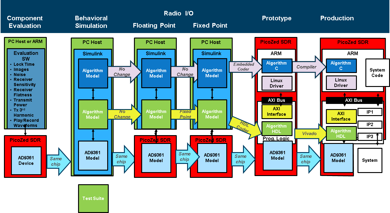
The first step of component evaluation is to understand if the AD9361 will meet your requirements (the component evaluation stage). Since the AD9361 can tune to 1090MHz (the broadcast frequency for ADS-B), and receive a 2MHz bandwidth signal (the channel bandwidth of ADS-B), the AD9361 is suitable.
The next step of behavioral simulation is to model and simulate the SDR system in Simulink. At this stage the communication algorithm is partitioned into blocks that will be implemented in software and blocks that will be implemented into the programmable logic or embedded software.
After verified in pure simulation environment, this model can be run with “Radio I/O”, where we are capturing signals off the air, and ensuring that our model works with real world impairments.
Once the partitioning and the simulation are complete, in the prototype stage, the SDR model is converted into C code and HDL using Embedded Coder and HDL Coder. A Zynq-based prototyping system is used to verify the performance of the communication algorithm and to help further tune the SDR model before moving to the actual production stage.
Finally, in the production stage the automatically generated C code and HDL are integrated into the complex production system framework. This workflow ensures that once the communication algorithm reaches the production stage it is fully verified and tested and provides a lot of confidence in the system’s robustness.
In each step of this process, we need to test the models with a pre-defined test suite, to make sure we get consistent results throughout the process.
Component Evaluation
Wireless signals that can be detected and decoded are everywhere, and they are easily accessible with today’s Software Defined Radio (SDR) hardware like the Analog Devices AD9361 integrated RF agile transceivers. The Automatic Dependent Surveillance Broadcast (ADS-B) transmissions from commercial aircraft provide a readily available wireless signal that can be used to demonstrate the Zynq and AD9361 rapid prototyping flow. Commercial aircraft use ADS-B transmitters to report their position, velocity, altitude and aircraft ID to air traffic controllers. The flight data format is defined in the International Civil Aviation Organization’s (ICAO) Mode S Extended Squitter specification. ADS-B is being introduced throughout the world to modernize air traffic control and collision avoidance systems. It has already been adopted in Europe and is being gradually introduced in the United States.
The Mode S Extended Squitter standard provides details of the RF transmission format and encoded data fields. The transponder transmission has the following properties:
Transmit Frequency: 1090 MHz
Modulation: Pulse Position Modulation (PPM)
Data Rate: 1 Mbit/s
Message Length: 56 usec or 112 usec
24-bit CRC checksum
The tuning frequency and bandwidth are well within the capabilities of the AD9361 RF transceiver, such as the PicoZed SDR board.
The Mode S waveform is fairly simple, as shown below, but there are still several challenges involved in receiving and decoding the transmitted messages.
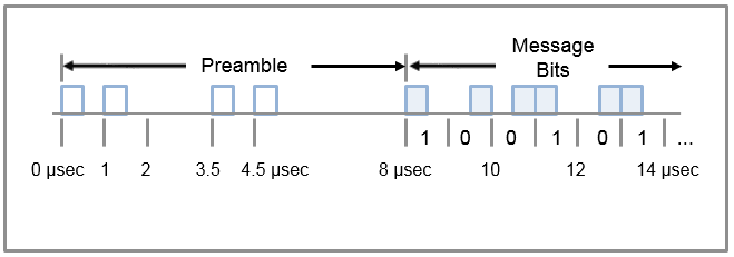
The receive environment typically contains very short messages interspersed with long idle periods. The signals being received can be very weak when the transmitting aircraft is a long distance from the receiver. Legacy waveforms are also transmitted at 1090 MHz. The receiver needs to use the preamble to identify both high and low amplitude Mode S transmissions in a congested frequency band.
Bits have one of two possible patterns within the 1 usec bit interval. A logical 1 is ON for the first 1/2 usec and OFF for the second 1/2 usec. A logical 0 is OFF for the first 1/2 usec and ON for the second 1/2 usec. Since the bit decisions are made based on time-based patterns, the receiver needs to use the preamble to accurately find the IQ sample where the message bits start.
The Mode S message is composed of 88 information bits and 24 checksum bits. The receiver needs to be able to clear registers, make bit decisions, compute the checksum and read the checksum registers at the correct times. Timing control is required for the receiver to function properly.
For an embedded design, the decoding process has to work on a sample by sample basis. Storing large amounts of data for batch processing is not a realistic receiver design for an embedded system.
The combination of a powerful RF front end like the AD9361 and a technical computing language like MATLAB greatly simplifies the problems associated with detecting and decoding these transmissions. Functions for the math and signal processing libraries can be used to identify the sync pattern, calculate the noise floor, make bit decisions and calculate the checksum. The conditional and execution control functions in MATLAB simplify the control logic. Accessing test data is easy, both from binary or text files or streamed directly into MATLAB using the AD9361 SDR platforms.
Behavioral Simulation
Transmit Model
In order to verify the receiver model works properly, especially the detect and decoding algorithm, we construct a transmit model from some known ADS-B message as a test suite.
The transmit model adsbTxGen.m can be found on the Analog Devices GitHub repository:
The input to this function is the known ADS-B message you would like to transmit, and the output is the baseband ADS-B waveform that the receiver can handle. In the MATLAB command window, run the following line:
txData = adsbTxGen('8D86D5E058135037C0A9112B72B7');
It will generate the waveform for the message ‘8D86D5E058135037C0A9112B72B7’.
The waveform is saved in the variable txData. You can either leave this
variable in the workspace if you will try out the receiver model right away, or
save it in a mat file for future reference.
Receive Model
The receiver model ModeS_Simulink_Decode.mdl and its associated files can be found on the Analog Devices GitHub repository:
The model itself is quite straightforward. It takes the pre-recorded ADS-B
data, saved in data_Yb.mat as input, and then decode the message. The subsystem
of decoding algorithm is shown in the figure below:
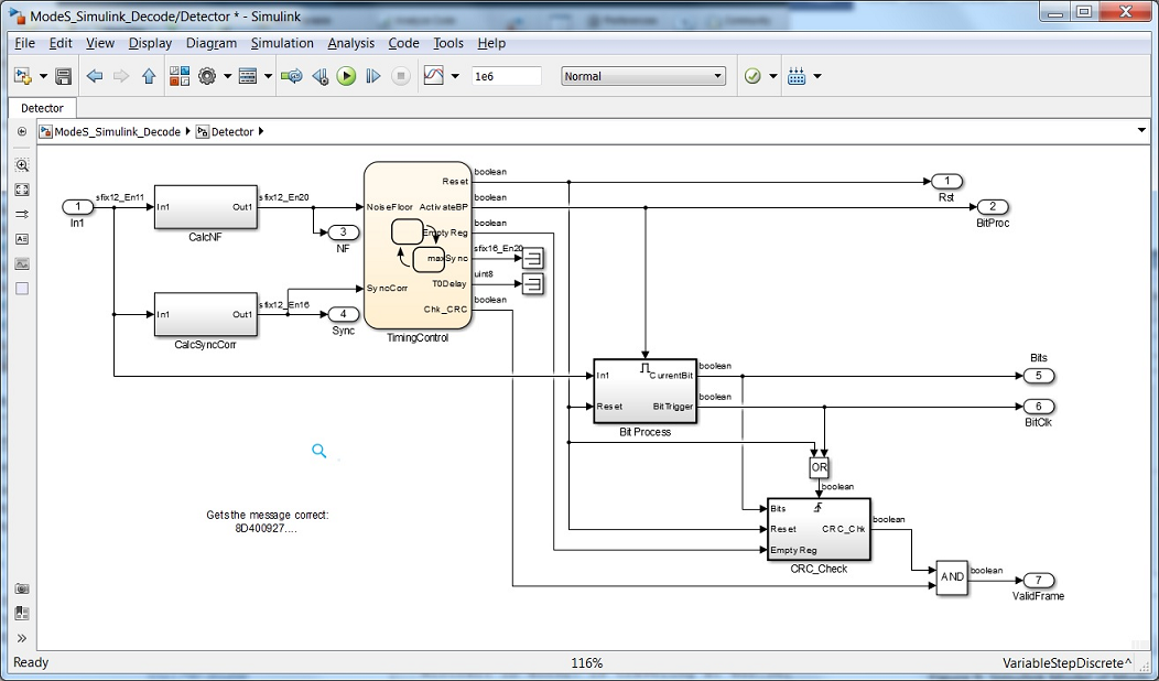
The first step in the decoding is to calculate the noise floor and the correlation to the preamble. Digital filter blocks are used for these calculations. The TimingControl is implemented using Stateflow, which is a state machine tool that is used to generate the timing, reset and control signals for the rest of the decoding algorithm. Stateflow is very useful for models where you want to separate the control logic from the data flow. Once the timing and triggers are activated the block named Bit Process takes the input IQ samples and calculates the data bits, and the CRC_Check block computes the checksum. The message parsing takes place in a MATLAB script named DecodeBits.m driven by this Simulink model.
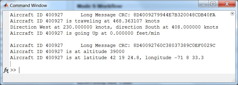
After you run the model, the figure below from the MATLAB command window shows the two messages that were successfully decoded from the one million sample data set. The hex characters that make up the 88-bit message and 24-bit checksum are displayed, and the results of the decoding process show the aircraft ID, message type, and aircraft velocity, altitude, and position.
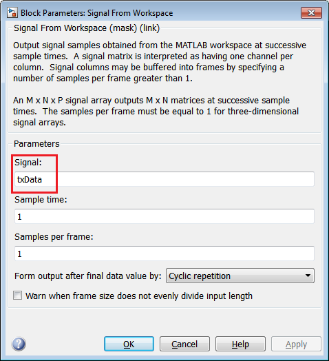
In order to verify the detect and decoding algorithm works properly, double
click on the Signal From Workspace block, and use the synthetic data txData
we just created as the signal source:
Click play button to run the model. In the command window, you will see the following results:
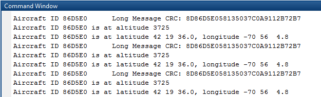
Since we select the cyclic repetition mode for txData, the decoded result
will repeat until the simulation ends. As you can see, the decoded result
matches what we have transmitted, so it verifies the receiver model, including
the detect and decoding algorithm, works properly.
Radio I/O
After implementing any signal processing algorithm in MATLAB or Simulink, the next natural step is to verify the algorithm’s functionality using real data acquired from the actual SDR hardware system that it is going to run on. In the previous step, the verification of the algorithm is done using different sets of input data captured from the system. This helps validate the algorithm’s functionality, but does not guarantee that the algorithm will perform as expected in environmental conditions other than the ones used to make the data captures, or what the behavior and performance will be for different settings of the analog frontend and digital blocks of the SDR system. In order to verify all of these aspects, it is very beneficial if the algorithm can be run online, receiving live data as input, and tuning the settings of the SDR system for optimal performance.
In this section, we will describe and showcase how to use IIO System Object to capture signals with the target transceiver, but still do the signal processing on the host in MATLAB and Simulink to decode the messages, as shown below:
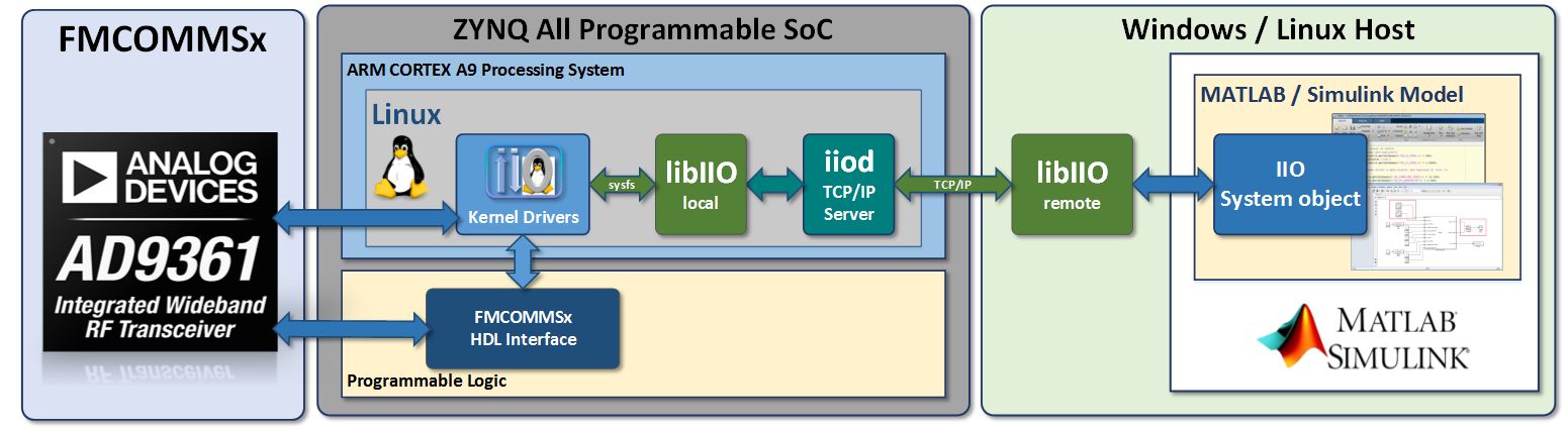
The algorithm will be designed with the ultimate goal of deploying the solution onto a Zynq SoC platform, such as PicoZed SDR board. Readers who are interested in following along with the radio I/O models can find the files on the Analog Devices GitHub repository:
To better understand these models, an introduction to IIO System Object provided by ADI can be found here.
MATLAB
To validate the MATLAB ADS-B decoding algorithm operation with real time data acquired from the PicoZed SDR platform, a MATLAB script ad9361_ModeS.m has been developed to perform the following operations:
Calculate the earth zone according to user input
Create and configure the IIO System object
Configure the PicoZed analog frontend and digital blocks through the IIO System object
Receive data frames from the SDR platform using the IIO System object
Detect and decode the ADS-B data
Display the decoded ADS-B information
After an IIO System object is constructed, it must be configured with the IP address of the SDR system, the target device name and input/output channels sizes and numbers. The following piece of code presents an example on how to create and configure the MATLAB IIO System object.
% System Object Configuration
s = iio_sys_obj_matlab; % MATLAB libiio Constructor
s.ip_address = ip;
s.dev_name = 'ad9361';
s.in_ch_no = 4;
s.out_ch_no = 4;
s.in_ch_size = n;
s.out_ch_size = n;
The IIO System object is then used to set the attributes of AD9361, and to receive the ADS-B signals.
% Set the attributes of AD9361
if strcmp(source,'pre-captured')
    input_content{s.getInChannel('RX_LO_FREQ')} = 6e9;
elseif strcmp(source,'live')
    input_content{s.getInChannel('RX_LO_FREQ')} = 1.09e9;
else
    error('Please select a data source: pre-captured or live.');
end
input_content{s.getInChannel('RX_SAMPLING_FREQ')} = 2.5e6;
input_content{s.getInChannel('RX_RF_BANDWIDTH')} = 10e6;
input_content{s.getInChannel('RX1_GAIN_MODE')} = 'fast_attack';
input_content{s.getInChannel('RX1_GAIN')} = 0;
input_content{s.getInChannel('RX2_GAIN_MODE')} = 'fast_attack';
input_content{s.getInChannel('RX2_GAIN')} = 0;
input_content{s.getInChannel('TX_LO_FREQ')} = 6e9;
input_content{s.getInChannel('TX_SAMPLING_FREQ')} = 2.5e6;
input_content{s.getInChannel('TX_RF_BANDWIDTH')} = 10e6;
The attributes of AD9361 is set up based upon the following considerations:
Sampling rate is quite straightforward with the AD9361 based platforms. Transmit date rate normally equals Rx date rate, and ultimately depends on the baseband algorithm. In this example, since the decoding algorithm is designed to work with the sampling rate of 2.5 MSPS, the date rate of AD9361 is set accordingly. By doing this, the received samples can be applied directly to the decoding algorithm, without any additional decimation or interpolation operations.
The RF bandwidth control sets the AD9361’s Rx analog baseband low pass filters’ bandwidth to provide anti-aliasing and out-of-band signal rejection. In order to correctly demodulate the received signals, the system must maximize signal-to-noise ratio (SNR). In order to do this, RF bandwidth needs to be set as narrow as possible while meeting flatness and out-of-band rejection specification to minimize in band noise and spurious signal levels. Therefore, setting the RF bandwidth at an optimal value is critical to receive desired in-band signals and reject out-of-band signals. By observing the spectrum of received signals, we find 10 MHz is a proper value for the RF bandwidth.
Besides setting up the analog filters of AD9361 via RF bandwidth attribute, we can also improve the decoding performance by enabling the digital FIR filters on AD9361 via the IIO System object. According to the spectrum characteristics of the ADS-B signal, we design an FIR filter with data rate of 2.5 MSPS, pass band frequency of 3.25 MHz and stop band frequency of 4 MHz. In this way, we can further focus on the bandwidth of interest.
s.writeFirData('adsb.ftr');
adsb.ftr is a file containing the coefficients of an FIR filter designed
using the Analog Devices AD9361 Filter Design Wizard. This
tool provides not only a general purpose low pass filter designer, but also
magnitude and phase equalization for other stages in the signal path.
The versatile and highly configurable AD9361 transceiver has several gain control modes that enable its use in a variety of applications. The Gain Mode parameter of the IIO System object selects one of the available modes: manual, slow_attack, hybrid and fast_attack. In the case of ADS-B, the fast attack gain mode provides the best results due to the bursty nature of these signals. In addition, fast attack mode is required for this waveform since there is preamble, the AGC needs to react fast enough so that the first bit is captured.
In the end, depending on how you set up the TX_LO_FREQ and
RX_LO_FREQ, there are two ways of using this model: using pre-captured
data (RF loopback) and using live data off the air.
Pre-captured Data
In this case, we are transmitting and receiving some pre-captured ADS-B signals
using PicoZed. These signals are saved in a variable called newModeS.
input_content{1} = (2^13).*newModeS./sqrt(2);
input_content{2} = (2^13).*newModeS./sqrt(2);
input_content{3} = (2^13).*newModeS./sqrt(2);
input_content{4} = (2^13).*newModeS./sqrt(2);
The requirement for this case is to make TX_LO_FREQ = RX_LO_FREQ, and
it can be any LO frequency value that PicoZed supports. Due to the nature of
pre-captured data, there is plenty of ADS-B valid data in there, so it is a
good way to verify whether the hardware setup is appropriate.
Live Data
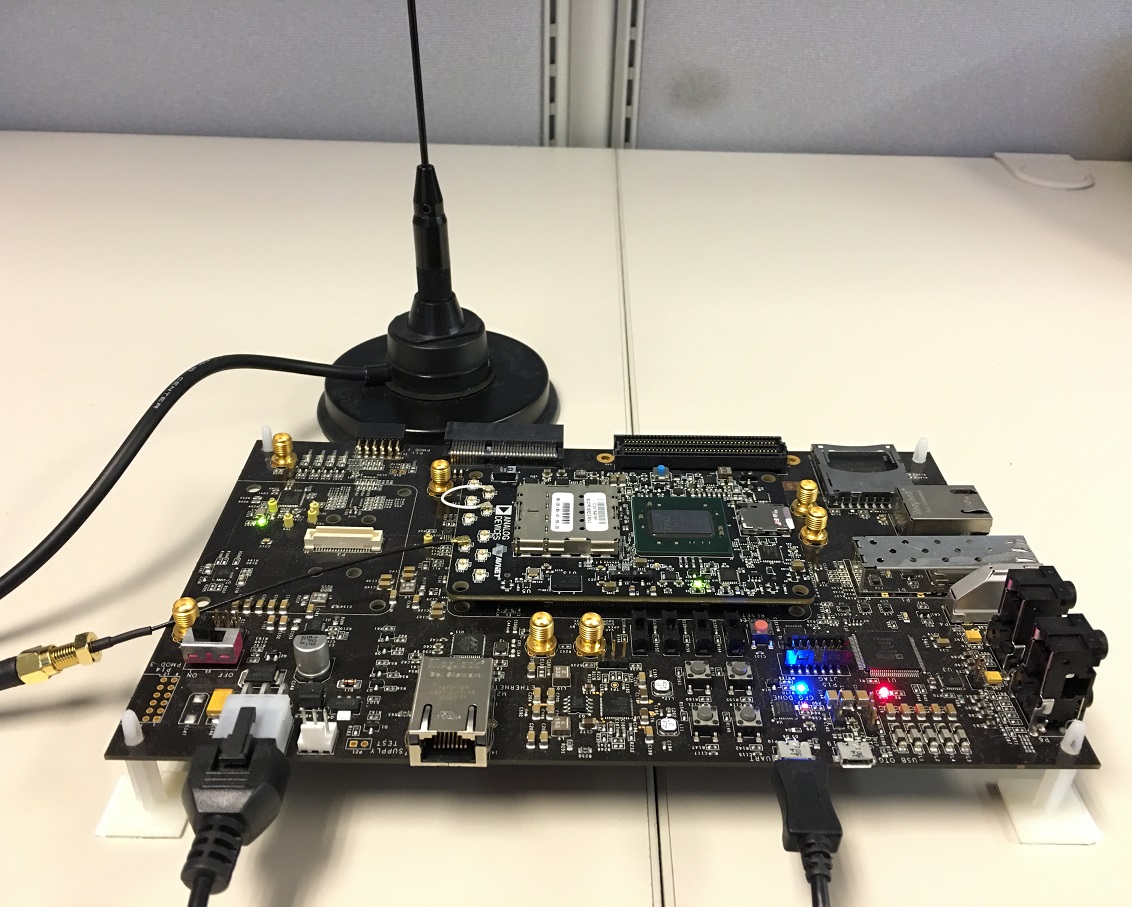
In this case, we are receiving the real-time ADS-B signals over the air, instead of the signals transmitted by PicoZed. According to ADS-B specification, it is transmitted at the center frequency of 1090 MHz, so the requirements for this case is:
RX_LO_FREQ= 1090 MHz,TX_LO_FREQfar away from 1090 MHz in order to avoid interferenceUse a proper antenna on the Rx side, which is capable of covering the 1090 MHz band. Using a poorly tuned or poorly made antenna will result in a lack of range for your air radar.
With everything set up properly, in order to run the MATLAB model, simply use the following command:
[rssi1,rssi2]=ad9361_ModeS('ip','data source',channel);
where ip is the IP address of the SDR board, and data source specifies
the data source of the received signal. Currently, this model supports data
sources of ‘pre-captured’ and ‘live’. channel specifies whether signals
are received using Channel 1 or Channel 2 of the PicoZed.
For example, the following command receives the pre-captured data on Channel 2:
[rssi1,rssi2]=ad9361_ModeS('192.168.10.2','pre-captured',2);
At the end of the simulation, you will get the RSSI values on both channels in your command window, as well as the result tables shown below:
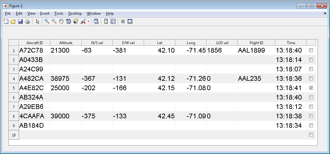
This result table shows the information of aircrafts appearing during the simulation. With a proper antenna, this model is able to capture and decode the aircraft signals in an 80 miles range with PicoZed. Since there are two types of Mode S messages (56 usec or 112 usec), some messages contain more information than the other.
When trying out this model with the real-world ADS-B signals, the signal strength is very important for successful decoding, so make sure to put the antenna in a good line of sight location with the aircraft. The received signal strength can be seen by looking at the RSSI values on both channels. For example, if receiving the signals on channel 2, the RSSI of channel 2 should be significantly higher than that of channel 1. You can tell whether there is any useful data by looking at the spectrum analyzer.
Simulink
The Simulink model shown below is based upon the model introduced in the behavioral simulation section. The detector and decoding piece comes directly from that model, and we add the Simulink IIO System object to conduct the signal reception and radio I/O simulation.
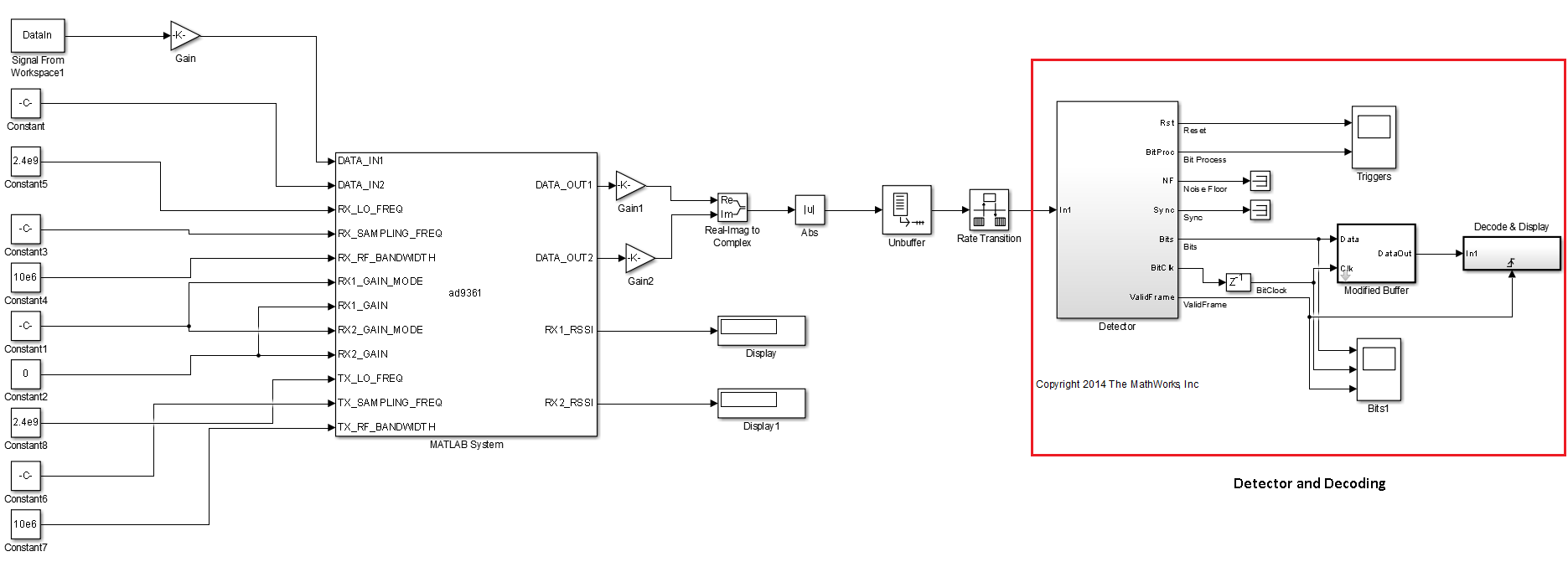
The original model works with sample time = 1 and frame size = 1. However, the Simulink IIO System object works in a buffer mode - it accumulates a number of samples and then processes them. In order to make the original model works with the System object, we added two blocks between them: unbuffer to make frame size = 1 and rate transition to make sample time = 1. By doing this, we can keep the original model intact.
The Simulink IIO System object is set up as below. Similar to the MATLAB one, it creates a System object, and then defines the IP address, device name, and input/output channels number and sizes related to this System object.
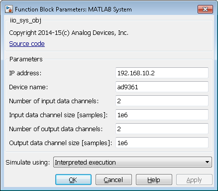
The input and output ports of this Simulink block corresponding to an IIO System object are defined through the properties dialog of the object’s block as well as through a configuration file that is specific to the targeted ADI SDR platform. The input and output ports are categorized as data and control ports. The data ports are used to receive/transmit buffers of continuous data from/to the target system in a frame based processing mode, while the control ports are used to configure and monitor different target system parameters. The number and size of the data ports are configured from the block’s configuration dialog while the control ports are defined in the configuration file. The attributes of AD9361 is set up according to the same factors as introduced in MATLAB model. The only difference is the Tx/Rx sampling frequency. We use 12.5 MSPS in the Simulink model, instead of 2.5 MSPS used in the MATLAB model, since here, we do not up sample by 5 on the receiver side, as we did in the MATLAB example. All the other theories and methods employed in the MATLAB model can be applied here.
Depending on how you set up the TX_LO_FREQ and RX_LO_FREQ, this
Simulink model can be run in two modes: using pre-captured data and using
live data.
In order to verify this model works properly, we run it in pre-captured mode,
and use the txData generated by the transmitter model as the signal
source, as shown below:
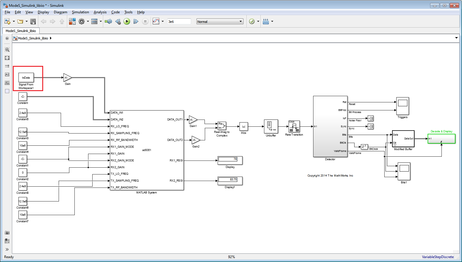
In the command window, we get the same decoded message as the one we transmit, which means the Simulink model using libiio also works properly.
Prototype and Production
In this section, we will show how to take the algorithm developed in behavioral simulation, verified in pure simulation and radio I/O, and use HDL Coder and Embedded Coder from MathWorks to generate code and deploy it in the production hardware. It enables rapid design iteration cycles and helps to detect and correct design and specification errors early.
Intermediate Model
The following guide outlines recommended practices for creating a design that can be implemented in hardware efficiently, and for optimizing the generated HDL for your targeted device.
According to the guidelines presented in the reference guide, the intermediate model ModeS_FixPt_Pipelined_ADI.slx and its associated files can be found on the Analog Devices GitHub repository:
In this model, we converted the data type from floating point to fixed point, and we added some pipeline registers as the first step for setting this model up for HDL code generation. It uses the same data set as the behavioral model, so you will get the same decoded messages.
Following this, there are two workflows to follow, one is HW/SW Co-Design provided by MathWorks, and the other is the MathWorks HDL Workflow Advisor flow using the HDL Workflow Advisor Board Support Package provided by ADI. It is recommended to use the HW/SW Co-Design whenever the hardware platform of interest is supported by this workflow.
MathWorks HW/SW Co-Design
Hardware-Software Co-Design is a standard workflow provided by MathWorks Communications System Toolbox Support Package for Xilinx Zynq-Based Radio. Using this workflow, you can prototype an algorithm in Simulink and then deploy it on the ARM processor and FPGA fabric of the Zynq hardware. The hardware-software co-design workflow includes FPGA targeting, HDL IP core generation, and the generation of a software interface model for execution on the ARM processor. To get started, see Hardware-Software Co-Design for Zynq SDR Applications.
The HW/SW Co-Design Implementation of ADS-B Transmitter/Receiver Using Analog Devices AD9361/AD9364 is a shipped example in MATLAB from R2016b. In this example, the stateflow block is removed and replaced with a MATLAB state machine, which means users without a stateflow license can use the model.
Since MathWorks example comes with detailed documentation, we are not going to elaborate here. However, just a reminder - do not forget to set up SDK tools:
Tip
SDK Tools Set Up
Within MATLAB, use Add-Ons > Get Hardware Support Packages to download Embedded Coder Support Package for Xilinx Zynq-7000 Platform.
Follow the installer instructions for installing the support package software.
You must then setup the SDK tools using the setup wizard. This will run automatically following installation. On the first pane, select Configure the Xilinx Design Tools. Click Next.
On the next pane, provide a valid path to the Xilinx SDK development tools. The default install path fills in automatically. Update the path if you installed the SDK in a nondefault location.
To complete the configuration, click Next.
If you already have the Embedded Coder Support Package for Xilinx Zynq-7000 Platform installed, you can start the setup wizard manually. On the MATLAB Home tab, in the Environment section of the Toolstrip, click Add-Ons > Manage Add-Ons. Locate Embedded Coder Support Package for Xilinx Zynq-7000 Platform and click Setup. Then follow the steps above.
Steps to Follow
In MATLAB 2016b, run the following two lines in command window:
>> hdlsetuptoolpath('ToolName','Xilinx Vivado','ToolPath','PATH_TO_YOUR_VIVADO.BAT_FOR_2015_4');
>> setupzynqradioipcoregen
Open
zynqRadioHWSWADSBAD9361AD9364SL.slx.Right click
HDL_ADSBsubsystem and launch HDL workflow advisor from there. Please note if you install both MathWorks HW/SW Co-Design and ADI Board Support Package, there might be some issues in Step 4.2 of HDL Workflow Advisor when using the HW/SW Co-Design flow. The solution is to uninstall the ADI Board Support Package.Go through all the steps in HDL workflow advisor. In the end, program the Zynq hardware.
Open the software interface model, run simulation in external mode and deploy to hardware.
Tip
In HDL workflow advisor Step 4.4, you can download the completed bitstream to the target and restart the board. You can also download the bitstream at the command line:
devzynq = zynq();
% The following address should match the board address
devzynq.IPAddress = '192.168.3.2';
% Path to the generated bitstream
devzynq.programFPGA(...
   'hdl_prj\vivado_ip_prj\vivado_prj.runs\impl_1\system_wrapper.bit')
This bitstream is not persistent across power cycles. If you want the
generated FPGA image to load each time you turn on the board, call the
downloadImage method:
radio = sdrdev('PicoZed SDR');
downloadImage(radio,'FPGAImage',...
   'hdl_prj\vivado_ip_prj\vivado_prj.runs\impl_1\system_wrapper.bit');
This call renames the generated system_wrapper.bit file to
system.bin and downloads the file over an Ethernet connection to the
radio hardware.
Tip
This example also works for receiving signals off the air, just comment out the transmitter block and adjust the receiver centre frequency.
For accurate position calculations, you will need to edit lines 8 and 9 of the position calculation script to give your current location.
>> edit zynqRadioHWSWADSBPositionCalcSingle
Target an ADS-B Airplane Tracker Using HW/SW Co-Design Workflow is also available on the Ettus E310 SDR platform.
ADI Board Support Package for the HDL Workflow Advisor
The ADI Board Support Package (BSP) for the HDL Workflow Advisor, based upon the MathWorks Board and Reference Design Registration System, is a collection of board definitions and reference designs that provide to the MathWorks HDL Workflow Advisor, which is capable of:
Generate IP blocks compatible with Analog Devices HDL reference designs for various Analog Devices platforms,
Automatically insert the generated IPs into the Analog Devices Vivado HDL reference designs.
A general introduction to the ADI Board Support Package can be found here. In this section, we will go through the steps to apply board support package towards ADS-B model.
Step 1: Download and install BSP
The board support package can be found at Analog Devices GitHub:
To install the Analog Devices BSP, set the MATLAB current folder to the
/vendor/AnalogDevices folder found in the location where the BSP was
downloaded and run
>> AnalogDevices.install
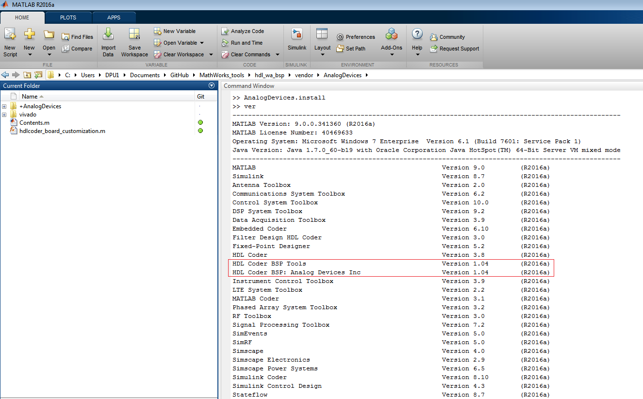
in the MATLAB command window. After the installation process is complete, run
ver in the MATLAB command window to list all the installed packages. If
the installation was successful, the HDL Coder BSP Tools and
HDL Coder BSP: Analog Devices Inc should appear in the list, as shown
below:
Tip
To uninstall the Analog Devices BSP, run this in the MATLAB command window:
>> AnalogDevices.uninstall
Step 2: Setup Xilinx tools
Xilinx Vivado 2015.2.1 is required in this process.
In MATLAB, run the following line in command window:
>> hdlsetuptoolpath('ToolName','Xilinx Vivado','ToolPath','PATH_TO_YOUR_VIVADO.BAT_FOR_2015_2_1');
Step 3: Download and open model
The ADS-B hardware targeting model can be found at Analog Devices GitHub:
Open model ModeS_ADI_Codegen.slx in MATLAB.
Step 4: Go through HDL Workflow Advisor
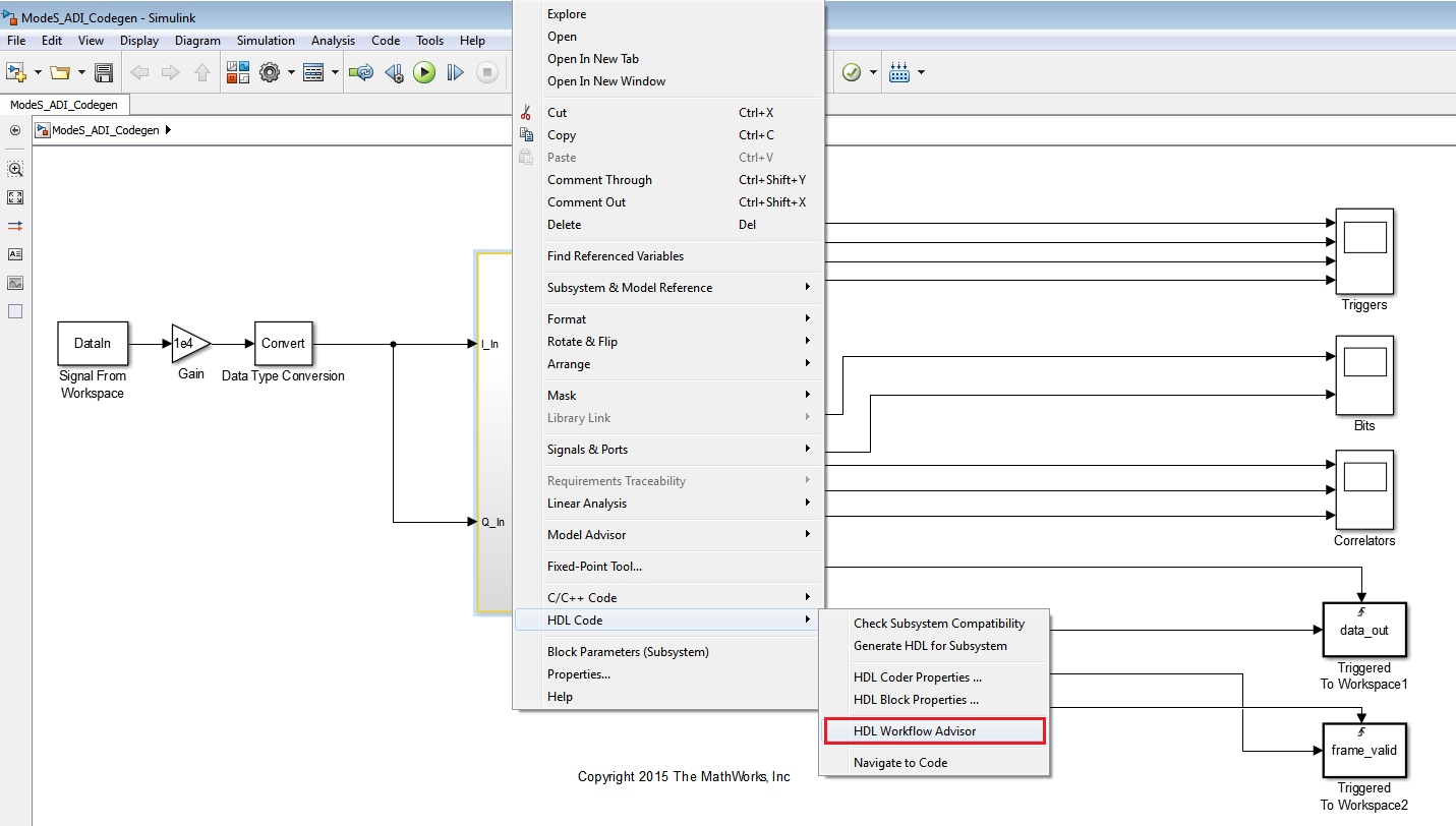
Right click on Detector subsystem, choose HDL Code from the menu, and
click on HDL Workflow Advisor to launch this tool, as shown below:
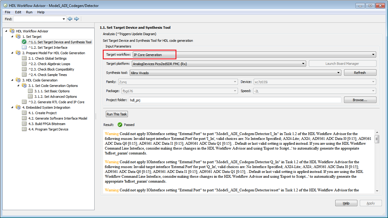
In step 1.1, select IP Core Generation for Target Workflow:
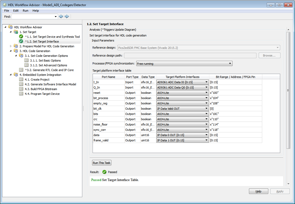
In step 1.2, set target interface as below, where all the signals we want to observe are set as AXI4-Lite:
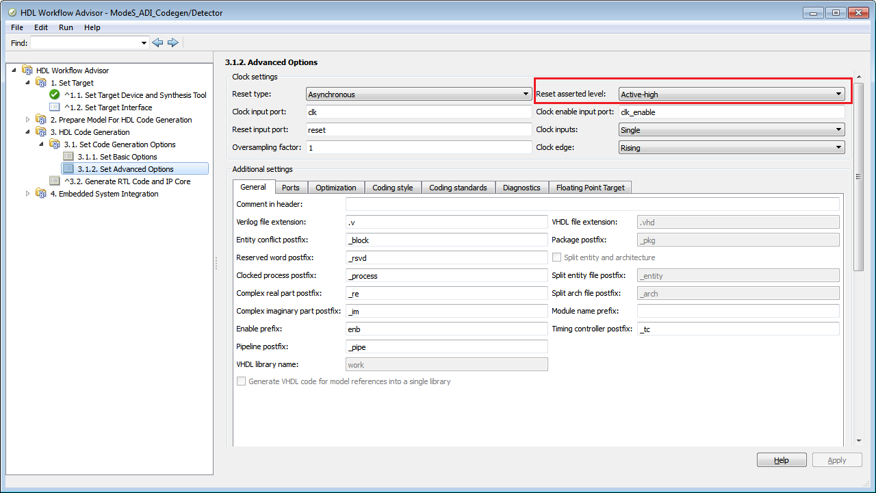
In step 3.1.2, set reset asserted level to Active-high:
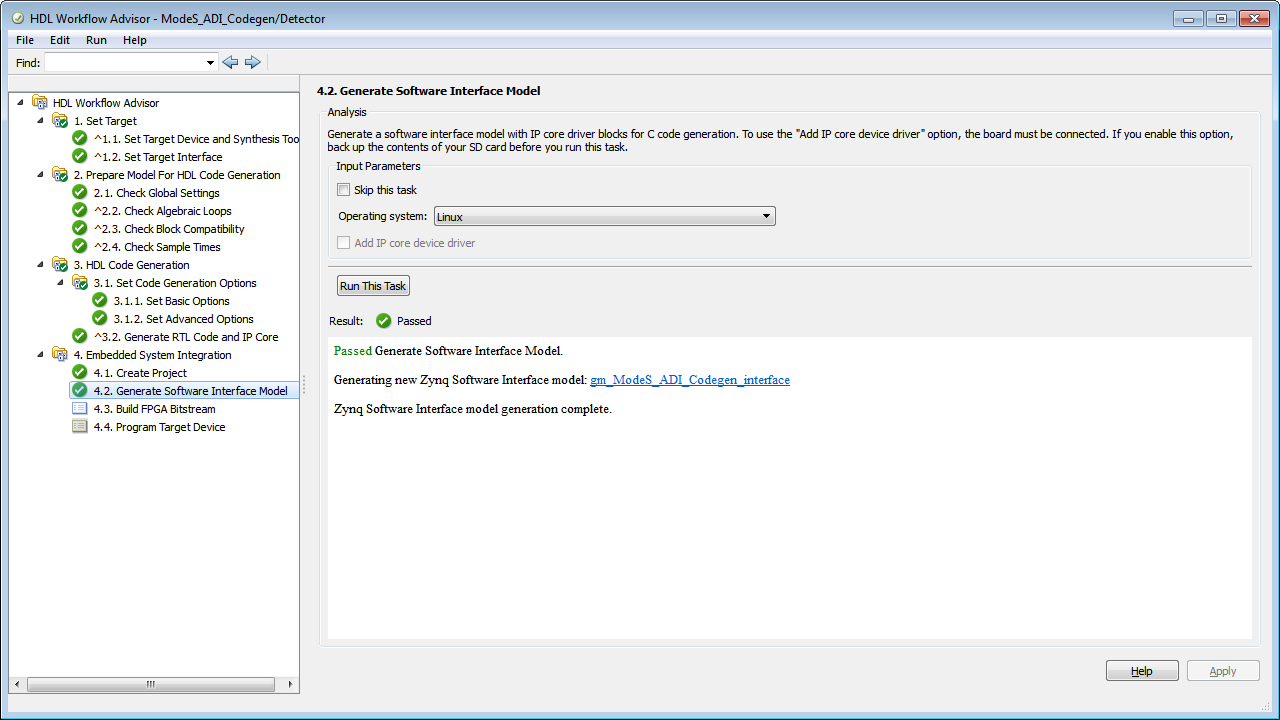
Then, run each task including Step 4.2. In the end of Step 4.2, you will see a software interface model generated. The external mode runs in this model, which will be introduced later.
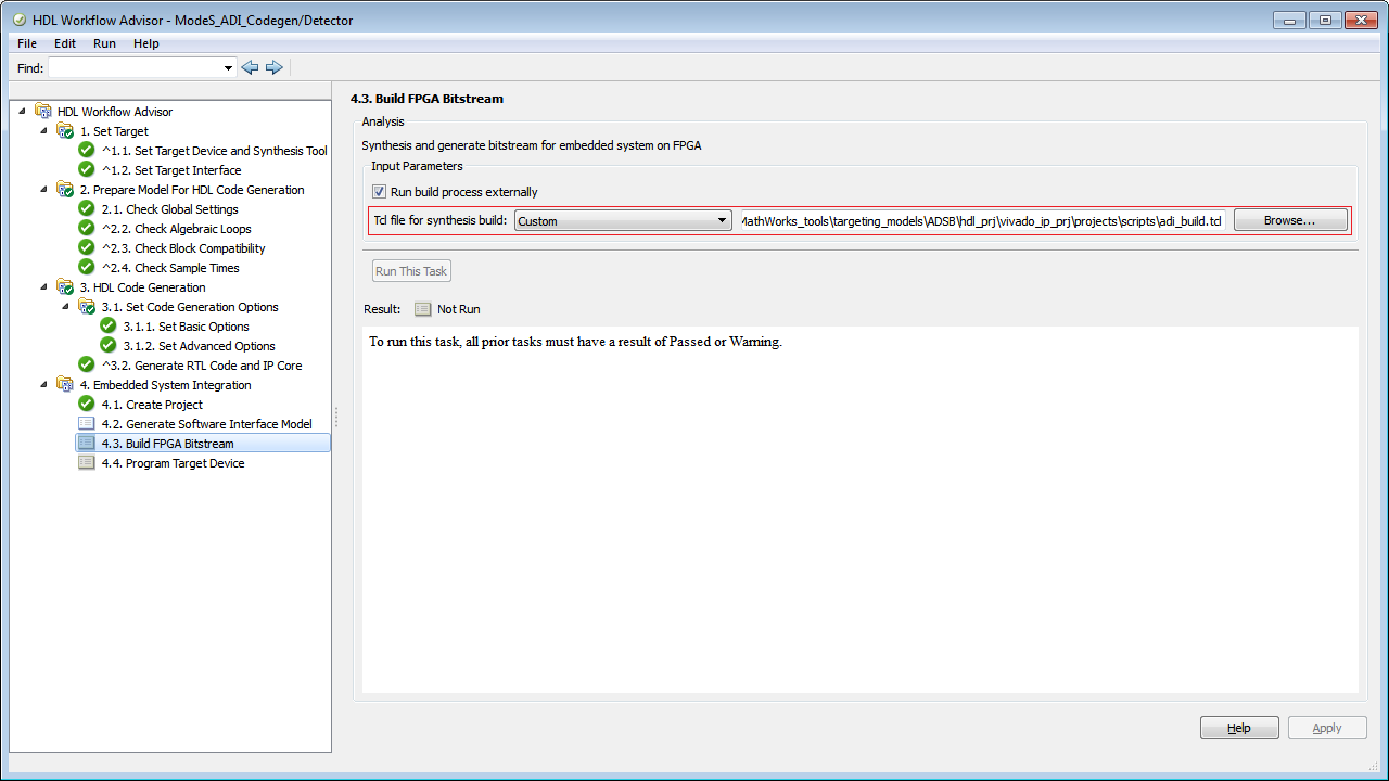
In Step 4.3, select Custom for Tcl file for synthesis build, and use
adi_build.tcl from
\ADSB\hdl_prj\vivado_ip_prj\projects\scripts\ folder:
Tip
adi_build.tcl is a generic file used to automate the build process for
BOOT.BIN. You can use it in other ADI BSP projects.
For the other steps not mentioned above, use default settings from HDL Workflow Advisor.
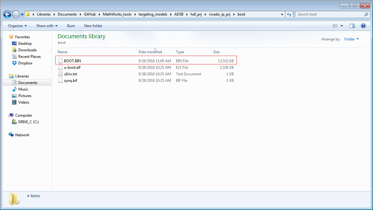
After Step 4.3 finishes running, you will find the newly generated
BOOT.BIN inside \ADSB\hdl_prj\vivado_ip_prj\boot\ folder:
Step 5: Copy and paste the generated BOOT.BIN onto SD card
Use the latest image from ADI. Replace the BOOT.BIN on SD card with the newly generated BOOT.BIN from HDL Workflow Advisor.
Step 6: Use MATLAB Coder to generate C code
Open DecodeBits_ADI.prj from your ADSB model folder and fill in the
settings as following:
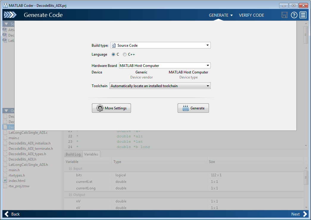
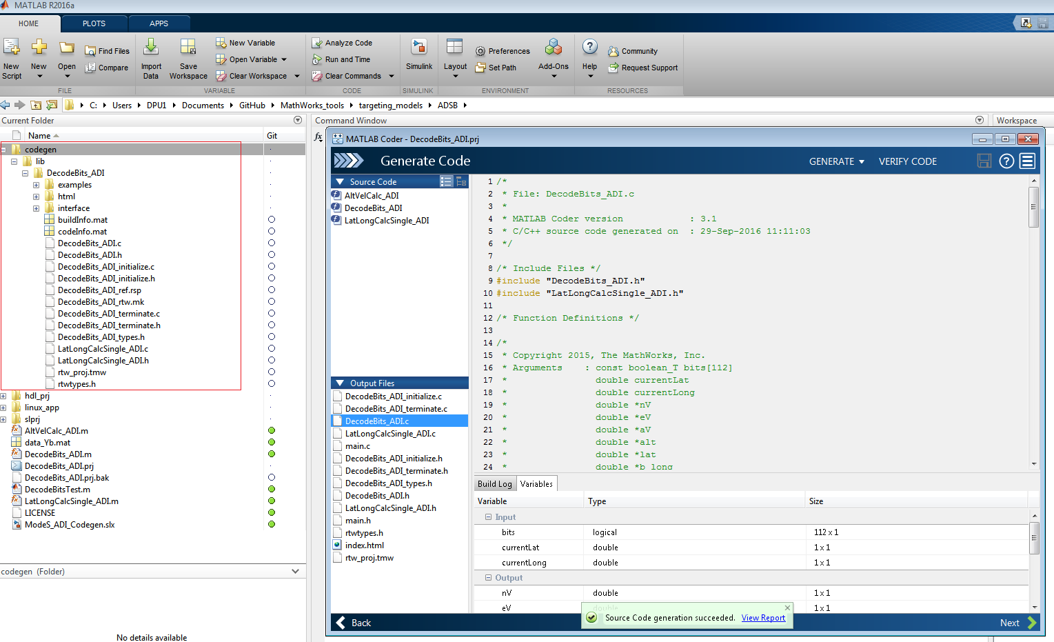
Then click the “Generate” button, and the code generation process will run
automatically. In the end, you will find a new folder called codegen in
your current MATLAB directory, which includes the files generated from MATLAB
Coder.
Step 7: Interface the C code with the data from FPGA
The generated C code contains the implementation of the ADS-B data decoding
algorithm, but does not contain the functions needed to configure the radio
and acquire the data from the ADS-B IP. The easiest way to achieve these two
tasks is to use the libiio support for the AD9361 and create an application
which uses the libiio functions to configure the radio and read the data from
the ADS-B IP through the DMA and afterwards call the auto-generated ADS-B
decoding C code. This application is provided together with the ADS-B model.
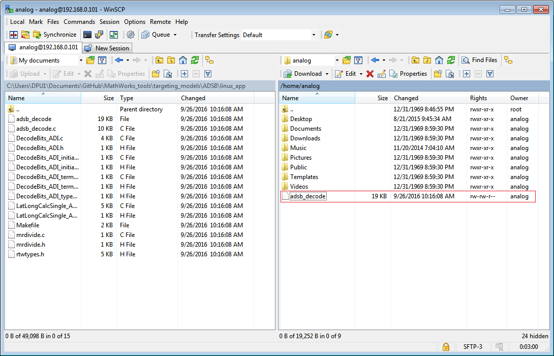
It is called adsb_decode.c and can be found in the linux_app folder
from your ADSB model folder, together with the auto-generated C code provided
there for reference. The next step is to copy the auto-generated C code along
with adsb_decode.c and the Makefile found in the linux_app folder to your
SD card and build the application under Linux by running the make all
command in the location where the files were copied. The resulting binary file
is called adsb_decode and can be ran to verify the system’s
functionality. This file is also provided for reference in the linux_app
folder.
To transfer the files to your Linux system. You can use tools such as WinSCP:
Tip
If you want to run the adsb_decode binary file provided in the
linux_app folder you must change the access permission of
adsb_decode after you have had it transferred to your Linux system.
You can do it by using the chmod command in a terminal:
chmod +x adsb_decode
Step 8: Observe the results
Use pre-captured data to verify
Before we use adsb_decode to decode real world ADS-B signals, we can
verify this file, the new BOOT.BIN, as well as the hardware settings using
some pre-captured data and the
ADI IIO Oscilloscope.
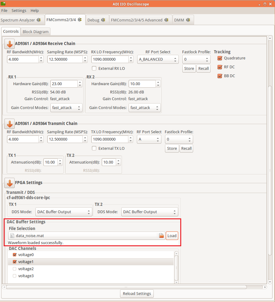
In IIO scope, set the Receive Chain and Transmit Chain according to the
specifications of ADS-B signals. Then, use DAC Buffer Output for DDS
Mode. In the end, select file
data_noise.mat,
which includes the pre-captured data and click Load. You will see the message
saying “Waveform loaded successfully” if your file has been applied to the DAC
channels you selected.
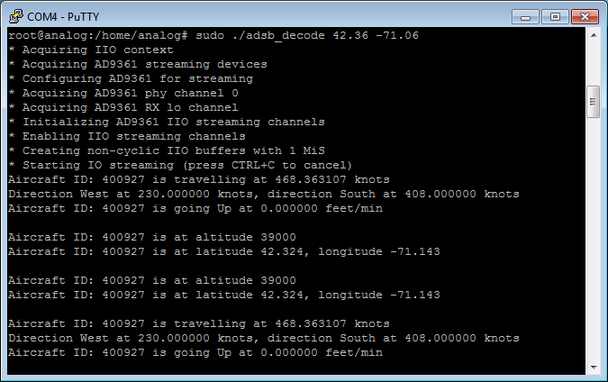
On Linux side, open a terminal and run the following command:
sudo ./adsb_decode 42.36 -71.06
You will see the following results almost immediately after you execute the command:
Tip
Use Ctrl + c to end the program.
Observe live data
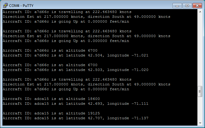
As soon as everything is verified by pre-captured data, we can move on to the live data. Connect the antenna to RX1A of the PicoZed. On Linux side, open a terminal and run the following command:
sudo ./adsb_decode lat lon
Note: lat and lon are latitude and longitude of your current location.
Wait a few seconds to a few minutes, depending on your local air traffic, and you will observe the decoded ADSB messages in the terminal, such as following:
Tip
For the actual field test, compare the ADS-B information decoded by the system with the data provided by airplane live tracking websites (such as flightradar24.com), and see whether the decoding algorithm displays the correct aircraft ID, altitude, speed, and latitude/longitude coordinates.
Use External Mode
With external mode, you can log signals and tune parameters while the model is running on the target hardware in real-time. When you change parameter values from within Simulink, the modified parameter values are communicated to the target hardware immediately.
The Analog Devices BSP also allows external mode for the supported Analog Devices boards. This enables the Simulink models used for IP core generation to be run in external mode and talk to the target hardware running the Analog Devices Linux distribution.
Before you run external mode, first set up the environment variable
'ADI_ZYNQ_SDR_IPADDRESS' to the IP address of your board. For example,
run the following line in the MATLAB command window:
>> setenv('ADI_ZYNQ_SDR_IPADDRESS', '192.168.3.2');
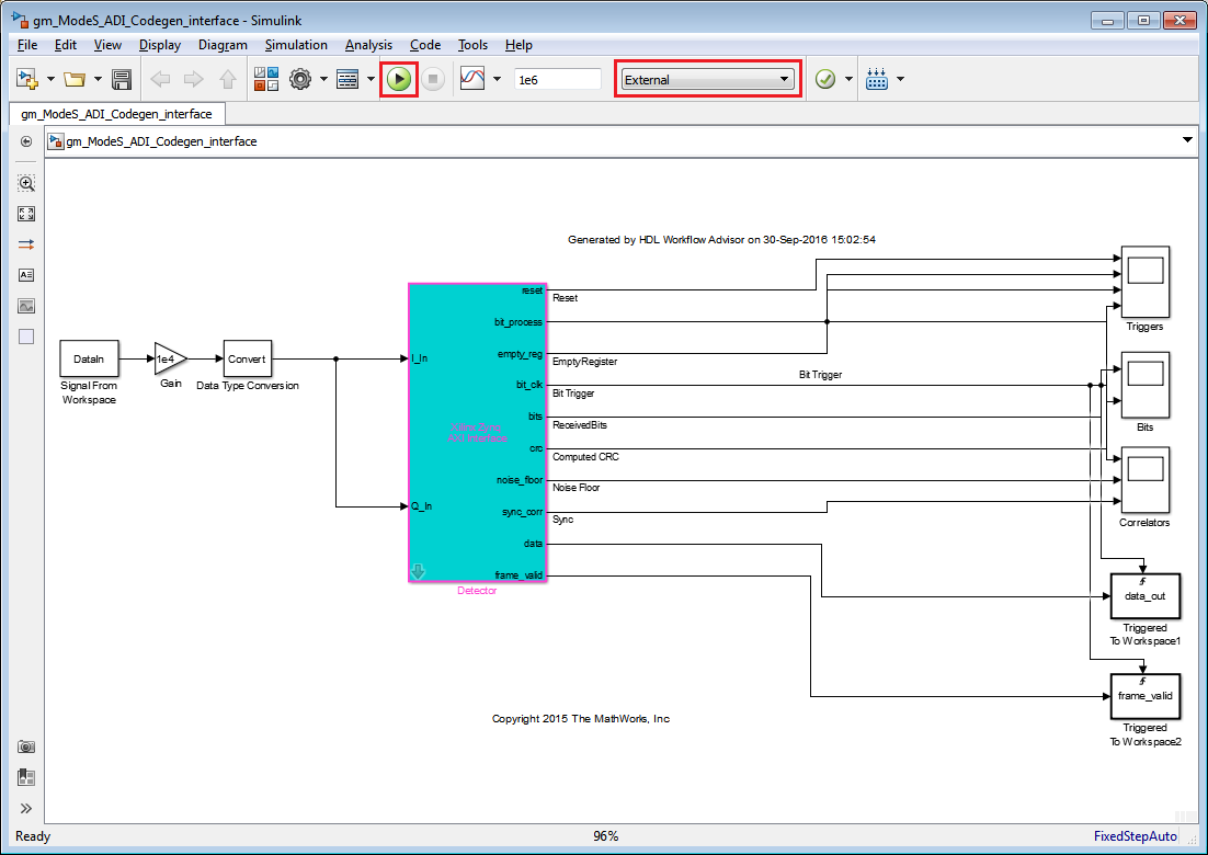
Open the software interface model generated in Step 4.2 of the HDL Workflow Advisor, as shown below:
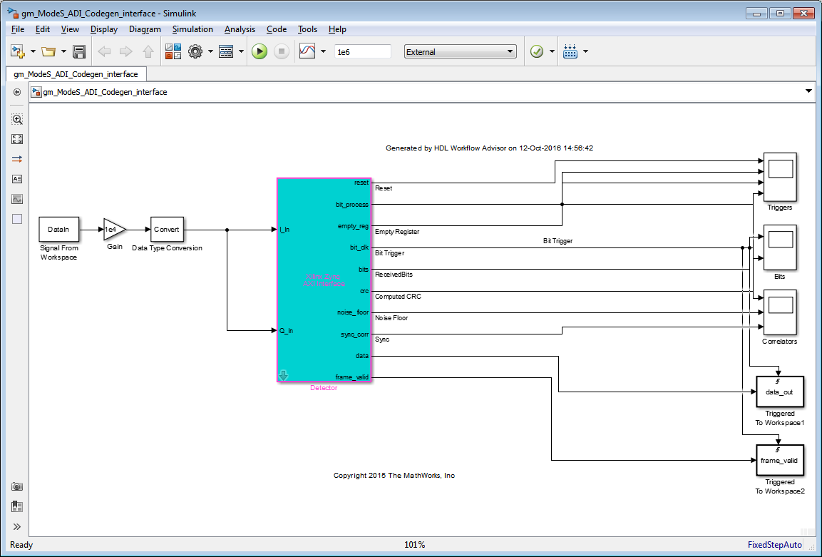
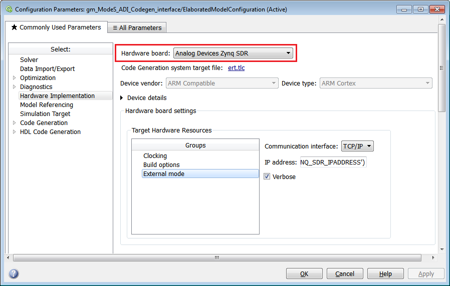
Before running the external mode, make sure that the “Hardware Implementation” options are set as below. Select Analog Devices Zynq SDR for Hardware board, and click Apply.
Go to “Code Generation” options, select Debug for Build Configuration, and click Apply:
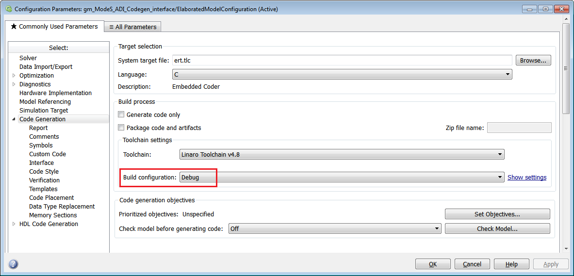
Now you can open the software interface model and run it in external mode. Select External from the menu, and click Play button.
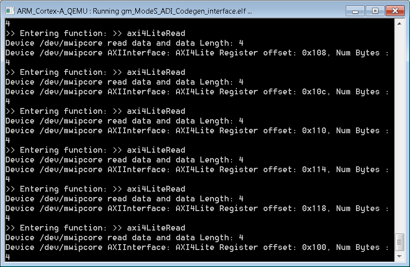
You will see a new terminal open up and show the results on hardware:
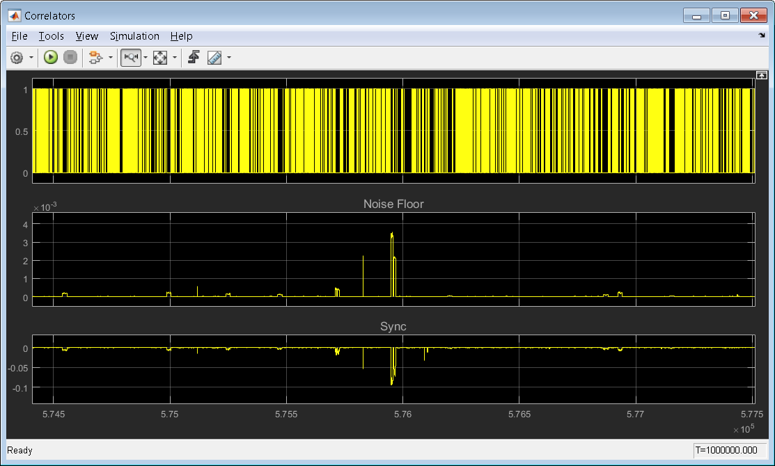
Besides, you can open each scope in the interface model and see how the signals behave on hardware. The following is a capture of the Correlators scope:
Reference
“Four Quick Steps to Production: Using Model-Based Design for Software-Defined Radio” Article Series
Di Pu, Andrei Cozma, and Tom Hill. “Part 1 - the Analog Devices/Xilinx SDR Rapid Prototyping Platform: Its Capabilities, Benefits, and Tools”. Analog Dialogue, Volume 49, Number 3.
Mike Donovan, Andrei Cozma, and Di Pu. “Part 2 - Mode-S Detection and Decoding Using MATLAB and Simulink”. Analog Dialogue, Volume 49, Number 4.
Di Pu, and Andrei Cozma. “Part 3 - Mode-S Signals Decoding Algorithm Validation using Hardware in the Loop”. Analog Dialogue, Volume 49, Number 4.
Mike Donovan, Andrei Cozma, and Di Pu. “Part 4 - Rapid Prototyping using the Zynq SDR Kit and Simulink Code Generation Workflow”. Analog Dialogue, Volume 49, Number 4.
Support
If you have any questions about PicoZed / AD9361 or ADI BSP workflow, please ask on the EngineerZone. ADI Support
If you have any questions about ADS-B receiver algorithm or HW/SW Co-Design workflow, please contact MathWorks. MathWorks Support