AD936X Plugin Description
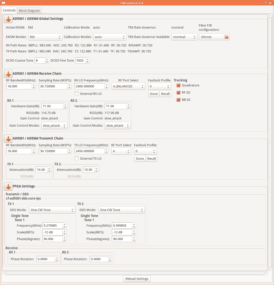
The AD936X plugin (formerly known as the FMCOMMS2/3/4 Plugin) works with the IIO Oscilloscope. You always use the latest version if possible. Changing any field will immediately write changes which have been made to the AD936X settings to the hardware, and then read it back to make sure the setting is valid. If you want to set something that the GUI changes to a different number, that either means that GUI is rounding (sorry), or the hardware (either the AD9361 or the FPGA fabric) does not support that mode/precision.
If you want to go play with /sys/bus/iio/devices/... and manipulate the
devices behind the back of the GUI, it’s still possible to see the settings by
clicking the “refresh” button at the bottom of the GUI.
If you think the device has a setting that isn’t managed by this tab, check out the AD936X Advanced Plugin for the IIO Oscilloscope.
The AD936X view is divided in four sections:
Device Global Settings
Receive Chain
Transmit Chain
FPGA Settings
Device Global Settings
For more details on ENSM see Enable State Machine Controls, on calibration see Calibration Mode Controls, on FIR filters see Digital FIR Filter Controls, and on DCXO see DCXO Tuning.
Active ENSM: Displays the active mode of the Enable State Machine.
ENSM Modes: Selects one of the available modes: FDD and TDD.
Calibration Mode: Displays the active calibration mode.
Calibration Modes: Selects one of the available modes: auto, manual, rf_dc_offs and tx_quad.
TRX Rate Governor: Displays the active option of the Rate Governors.
TRX Rate Governor Available: Selects one of the available options: nominal and highest_osr.
Filter FIR configuration: Allows a FIR filter configuration to be loaded from a file.
RX Path Rates: Lists the rates of: BBPLL, ADC, R2, R1, RF, RXSAMP.
TX Path Rates: Lists the rates of: TXSAMP, TF, T1, T2, DAC, BBPLL.
DCXO Coarse Tune: Selects the attribute for a coarse tune.
DCXO Fine Tune: Selects the attribute for a fine tune.
Receive Chain
For more details see RX RF Bandwidth Control, LO Control, Fastlock Mode, Tracking Controls, and RX Gain Control.
RF Bandwidth (MHz): Configures RX analog filters: RX TIA LPF and RX BB LPF.
Sampling Rate (MSPS): Selects the sample rate of the ADC.
RX LO Frequency (MHz): Selects the RX local oscillator frequency. Range 70 MHz to 6 GHz with 1 Hz tuning granularity.
External RX LO: Allows switching between external and internal LO on the fly.
RF Port Select: Selects the RF port to be used. Can be either any of the inputs on the Rx input mux (in single ended or differential) or the Tx monitor input.
Fastlock Profile: Selects one of the 8 available profiles of frequency configuration information.
Store: Stores the current frequency configuration into the profile pointed by Fastlock Profile.
Recall: Recalls the profile pointed by Fastlock Profile.
Tracking:
Quadrature
RF DC
BB DC
RX:
Hardware Gain (dB): Controls the RX gain only in Manual Gain Control Mode (MGC).
RSSI (dB): Displays the received strength signal level.
Gain Control: Displays the active gain mode.
Gain Control Modes: Selects one of the available modes: manual, slow_attack, hybrid and fast_attack.
Transmit Chain
For more details see TX RF Bandwidth Control, LO Control, Fastlock Mode, and TX Attenuation Control.
RF Bandwidth (MHz): Configures TX analog filters: TX BB LPF and TX Secondary LPF.
Sampling Rate (MSPS): Selects the sample rate of the DAC.
TX LO Frequency (MHz): Selects the TX local oscillator frequency. Range 70 MHz to 6 GHz with 1 Hz tuning granularity.
External TX LO: Allows switching between external and internal LO on the fly.
RF Port Select: Selects the RF port to be used.
Fastlock Profile: Selects one of the 8 available profiles of frequency configuration information.
Store: Stores the current frequency configuration into the profile pointed by Fastlock Profile.
Recall: Recalls the profile pointed by Fastlock Profile.
TX:
Attenuation (dB): Individually controls attenuation for TX1 and TX2. The range is from 0 to -89.75 dB in 0.25 dB steps.
RSSI (dB): TX Received Strength Signal Indicator. Active when TX_MONITOR port is selected in the RX RF Port Select.
FPGA Settings
Transmit/DDS
The plugin provides several options on how the transmitted data is generated.
It is possible to either use the built-in two tone Direct Digital Synthesizer (DDS) to transmit a bi-tonal signal on channels I and Q of the DAC. Or it is possible to use the Direct Memory Access (DMA) facility to transmit custom data that you have stored in a file.
This can be achieved by selecting one of the following options listed by the DDS Mode:
One CW Tone
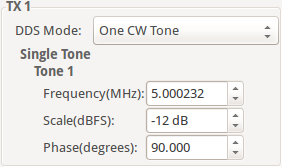
In One CW Tone mode one continuous wave (CW) tone will be outputted. The plugin displays the controls to set the Frequency, Amplitude and Phase for just one tone and makes sure that the amplitude of the other tone is set to 0. The resulting signal will be outputted on the Channel I of the DAC and the exact same signal but with a difference in phase of 90 degrees will be outputted on the Channel Q of the DAC.
Two CW Tones
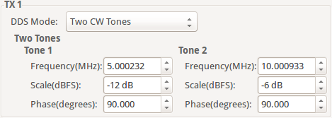
In Two CW Tone mode two continuous wave (CW) tones will be outputted. The plugin displays the controls to set the frequencies F1 and F2, amplitudes A1 and A2, phases P1 and P2 for the two tones. The resulting signal will be outputted on the Channel I of the DAC and the exact same signal but with a difference in phase of 90 degrees will be outputted on the Channel Q of the DAC.
Independent I/Q Control
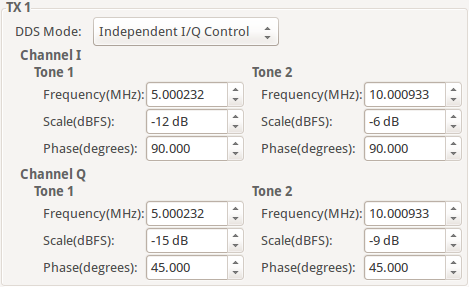
In Independent I/Q Control the plugin displays the controls to set the frequencies, amplitudes and phases for the two tones that will be outputted on channel I and additionally it allows for the two tones that will be outputted on channel Q of the DAC to be configured independently.
Note
The bi-tonal signal (T) is defined as the sum of two tones:
\(T(t) = A_1 \sin(2 \pi F_1 t + P_1) + A_2 \sin(2 \pi F_2 t + P_2)\)
where A is amplitude, F is frequency, P is phase of a tone.
DAC Buffer Output
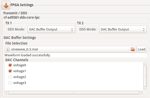
The file selector under the File Selection section is used to locate and choose the desired data file. Under the DAC Channels section the enabled channels will be used to transmit the data stored in the file. To finalize the process, a click on the Load button is required.
Restrictions:
There are two types of files that can be loaded:
.txtor.mat. The IIO Oscilloscope comes with several data files that can be used. If you want to create your own data files please take a look at the Basic IQ Data Files documentation first.Due to hardware limitation only specific combinations of enabled channels are possible. You can enable a total of 1, 2, 4, etc. channels. If 1 channel is enabled then it can be any of them. If two channels are enabled then channels 0, 1 or channels 2, 3 can be enabled and so on.
Disable
In this mode both DDS and DMA are disabled causing the DAC channels to stop transmitting any data.
Note
Upon pressing Reload Settings button the values will be reloaded with the corresponding driver values. Useful in scenarios where the driver values get changed outside this plugin (e.g. with the use of Debug plugin) and a refresh on plugin’s values is needed.
Some plugin values will be rounded to the nearest value supported by the hardware.