AD-FMCOMMS2-EBZ / AD-FMCOMMS4-EBZ / AD-FMCOMMS5-EBZ Specifications
The following equipment was used to generate the characterization data below. These specs are common to any of the boards which use a narrow band balun.
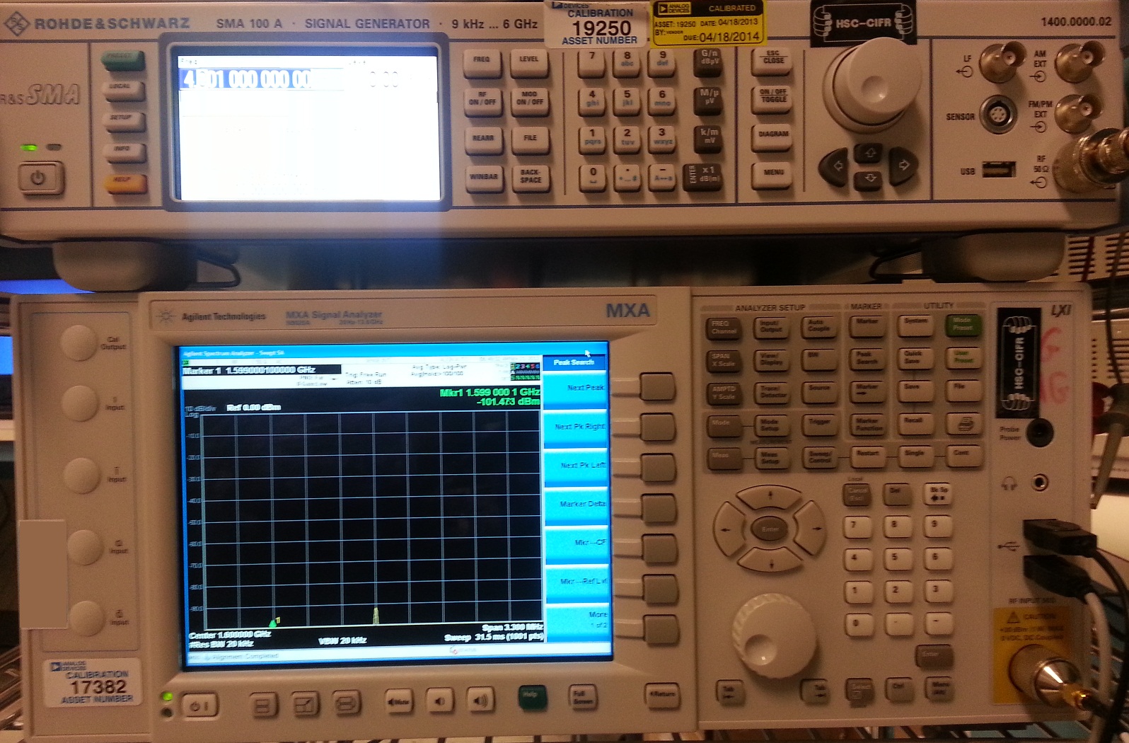
Figure 1 The Agilent Technology MXA Signal Analyzer and the Rohde & Schwarz SMA 100A Signal Generator.
Transmit Specs
LO BW
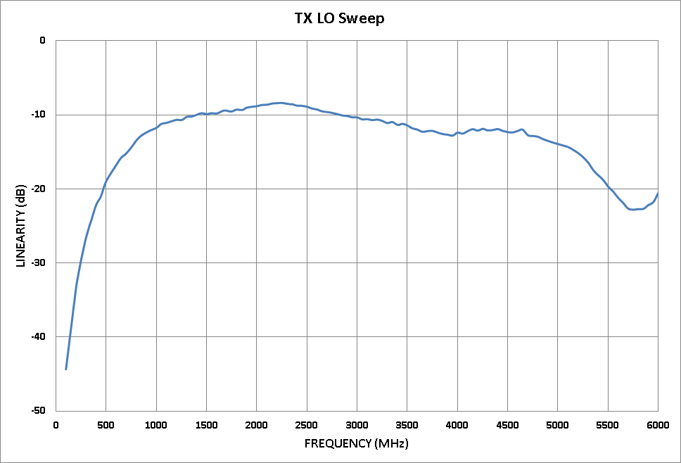
Figure 2 LO linearity sweep with 1 MHz tone, -10 dB attenuation and scale of 0.25.
Intermodulation Distortion


Phase Noise


EVM

Figure 9 EVM test result using LTE10, with 0 dB attenuation and 2.4 GHz LO.

Figure 10 EVM test result using LTE10, with -10 dB attenuation and 2.4 GHz LO.

Figure 11 EVM test result using LTE10, with -20 dB attenuation and 2.4 GHz LO.

Figure 12 EVM test result using LTE20, with 0 dB attenuation and 2.4 GHz LO.

Figure 13 EVM test result using LTE20, with -10 dB attenuation and 2.4 GHz LO.

Figure 14 EVM test result using LTE20, with -20 dB attenuation and 2.4 GHz LO.
Receive Specs
LO BW
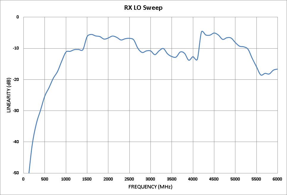
Figure 15 RX linearity LO sweep with 1 MHz tone, -10 dB input power and 10 dB hardware gain.

Figure 16 EVM using LTE10 with 2.4 GHz LO and -45 dBm input.

