Production testing of the AD-FMCOMMS2 / AD-FMCOMMS3 / AD-FMCOMMS4 / AD-FMCOMMS5
Overview
The production testing is quite simple. Since each board has been completely characterized, and we know the layout is good, we can just look for gross errors.
There are multiple test files for the different boards (all in GitHub):
test_fmcomms2-3_prod: used to test AD-FMCOMMS2-EBZ and AD-FMCOMMS3-EBZ
test_fmcomms4_prod: used to test AD-FMCOMMS4-EBZ
test_fmcomms5_prod: used to test AD-FMCOMMS5-EBZ
The tests and test parameters are in the pyadi-iio/tests/test_fmcomms2-3_prod.py file. This is broken down into the following sections:
- Temperature
- Voltage
- RF
- Peaks
- DCXO
- Loopback
Required hardware
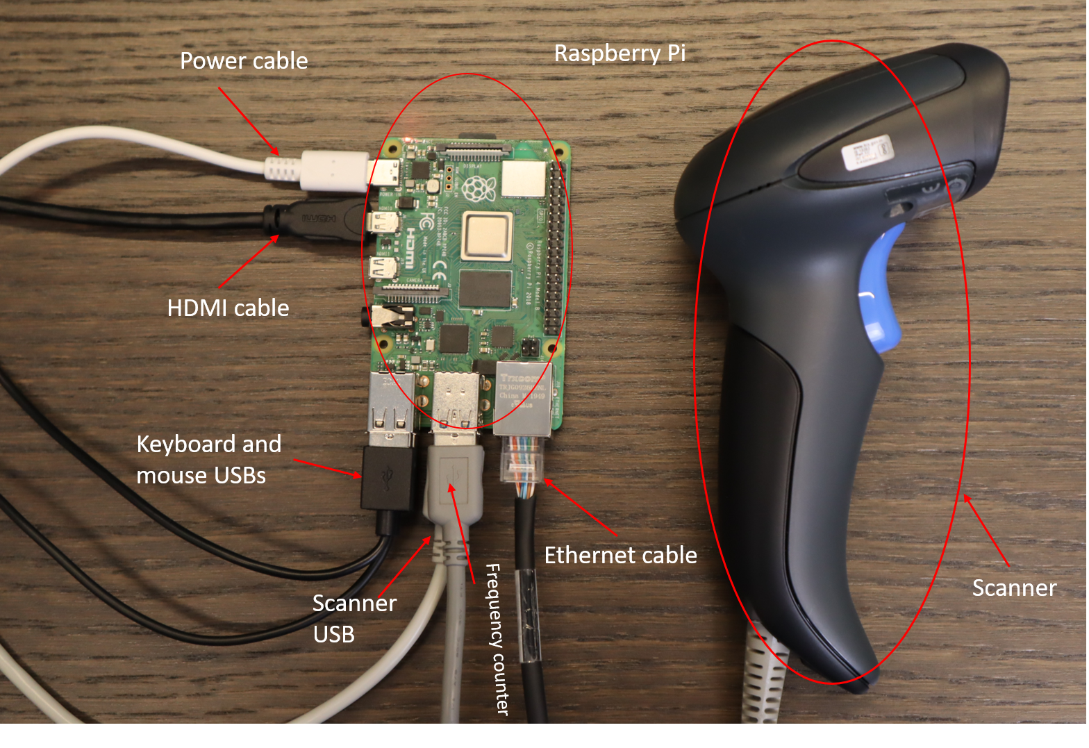
Raspberry Pi4
AD-FMCOMMS2-EBZ or AD-FMCOMMS3-EBZ or AD-FMCOMMS4-EBZ or AD-FMCOMMS5-EBZ card
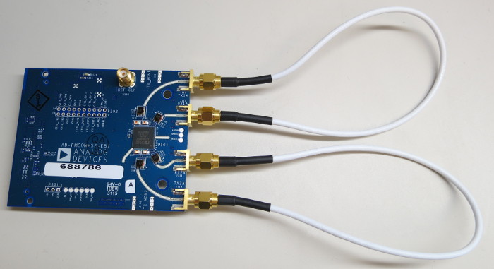
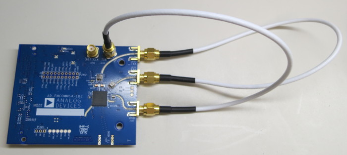
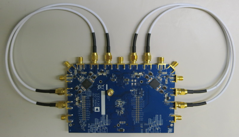
RF loopback cables (2x for FMCOMMS2/3/4, 4x for FMCOMMS5)
External monitor connected to the Raspberry Pi via micro HDMI
Keyboard and mouse (with USB hub if they aren’t part of a combo device)
Ethernet cable (needs to be plugged into the internet)
QR code scanner
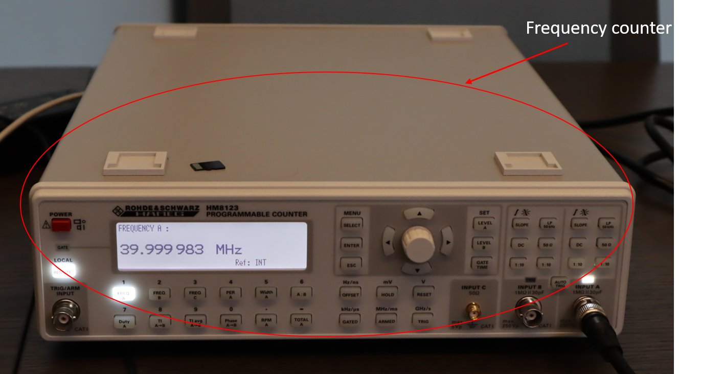
For the FMCOMMS2/3/4: Frequency counter with a USB-GPIB port (tested with an HAMEG Instruments, HM8123,5.12) and with a probe and grounding clip attachment
Required software
Creating a ZC706 carrier SD test card
First, write the latest available SD card image found to a spare card and prepare the card to boot into Linux.
Note
Different boards use different test scripts as seen in the following mapping:
test_fmcomms2-3_prod.py - FMCOMMS2/FMCOMMS3
test_fmcomms4_prod.py - FMCOMMS4
test_fmcomms5_prod.py - FMCOMMS5
Creating a Raspberry Pi SD test card
The SD image used is based on Raspbian with desktop.
Tip
To write an image on a SD card you can follow the instructions Installing Pi Images.
Required setup
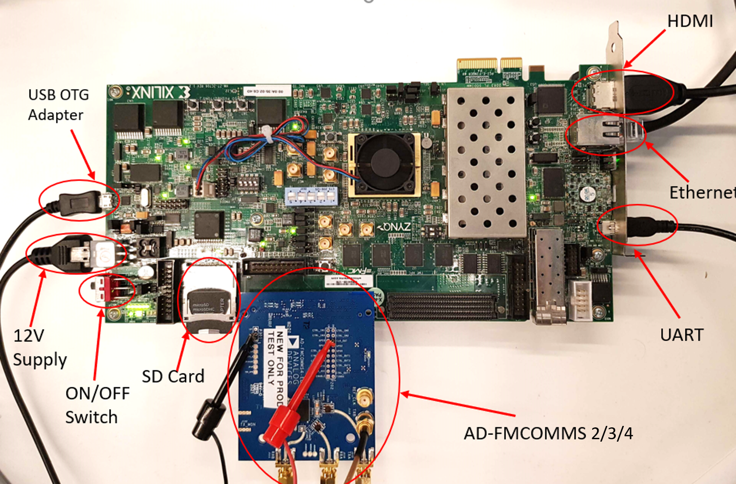
Attach the RF loopback cables to the board. The images at the bottom of the page show the correct placement for each type of AD-FMCOMMS board.
Insert the SD card into the carrier board.
Insert the FMCOMMS board onto the carrier.
Connect the HDMI cable to Raspberry Pi.
Connect USB keyboard to Raspberry Pi.
Insert SD card into Raspberry Pi.
Connect Ethernet cable between Raspberry Pi and the carrier.
Connect the scanner to Raspberry Pi.
Connect the frequency counter to Raspberry Pi.
Power the carrier board and Raspberry Pi.
Note
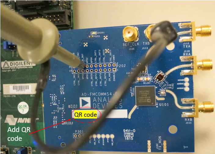
Before testing the board, please make sure to add a QR code sticker with the serial number as shown below.
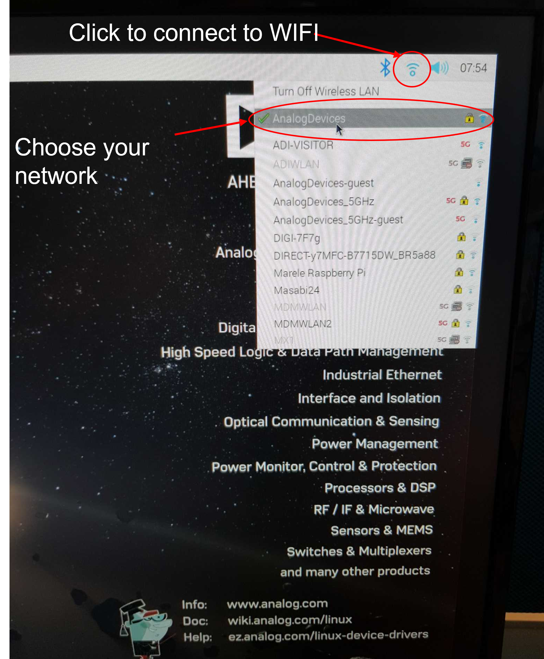
Make sure to connect to your WIFI Network before testing. You can exit the test window by pressing CTRL+C in order to access the connection. Reboot the system in order to return to the test window.
Test process
Firstly, make sure all the required steps from the setup explained above are completed. Once the setup is ready, testing should be done using the following steps:
Power the carrier board and the Raspberry Pi. The following screen will appear once the system has booted.
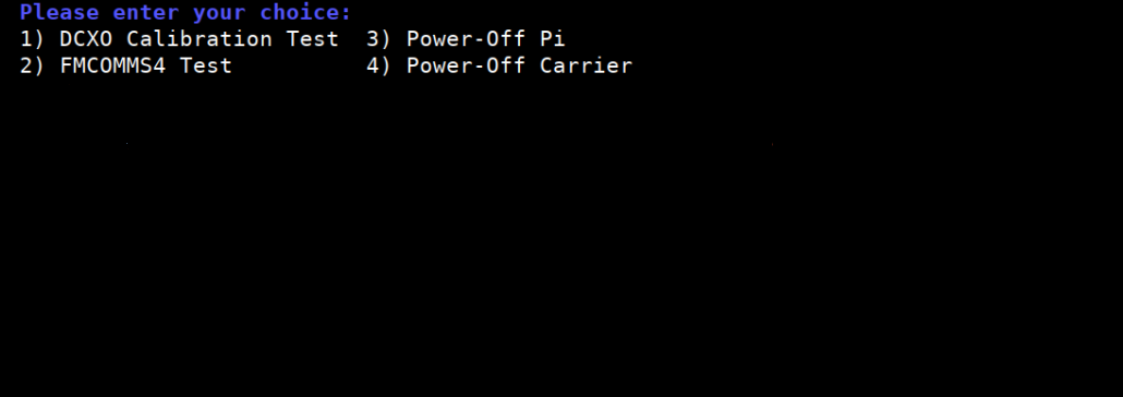
The testing sequence can be started by selecting one of the menu items. In order to start testing, an Ethernet cable should be connected between Raspberry Pi and DUT.
Start the DCXO test by writing the following command in the terminal: 1
At the beginning of every test, the connection with DUT is checked. If the connection is correctly established, the following message will be printed.
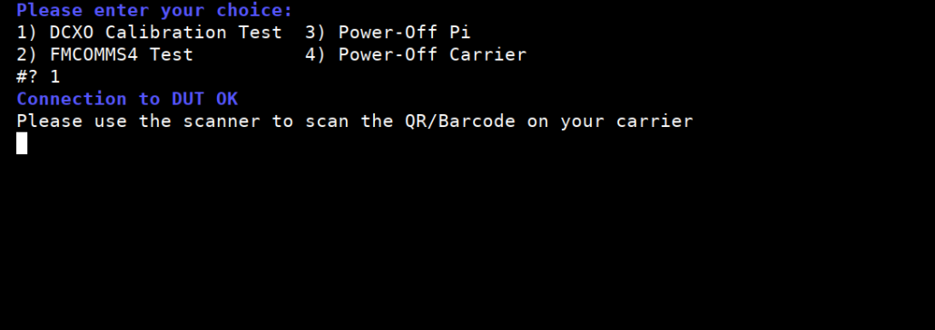
Use the scanner to scan the QR code on the board
If the DCXO test has been completed, the PASSED message will appear on the screen
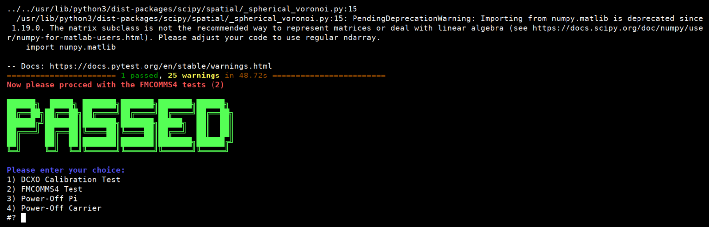
Secondly, start the FMCOMMS4 test by writing the following command in the terminal: 2
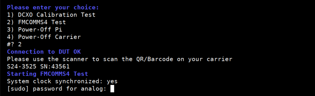
In the beginning, scan the QR code on the board
If connections are OK, the test will begin. Below is an example of a test running:
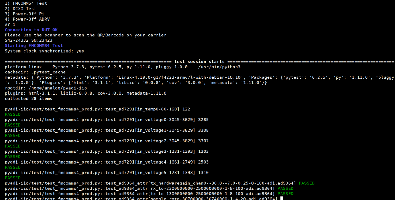
If the FMCOMMS test has been completed, the PASSED message will be printed on the screen. This means that the DUT passed all the assigned tests.

If one of the tests failed, the FAILED message will be printed as in the screen capture below:
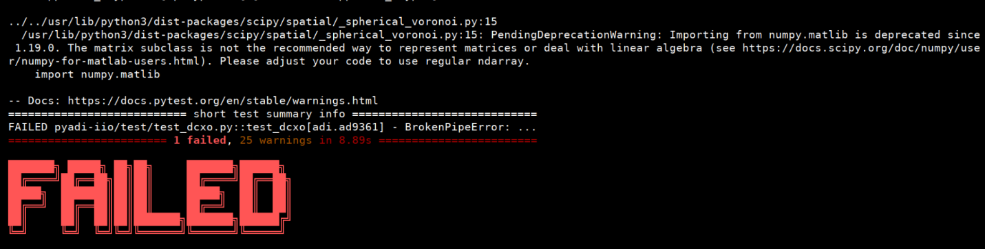
In case of a failed test, the tester can repeat the test immediately. The test can be repeated an undefined number of times.
After completing the test, power off the carrier by typing 4. After several seconds, power off the carrier board using the physical switch.
In order to power off Linux, please type 3 and enter.
Remove the FMCOMMS card and previously used board. Return to step 1 with the next board.
Important
When testing is finished, ZC706 and the Raspberry Pi should always be powered off from terminal before power is unplugged, otherwise the SD cards can be corrupted. First select item 4 to power off the carrier. After a few seconds, turn off the switch. After the ZC706 is off, the Raspberry Pi can be turned off selecting item 3.