Hardware
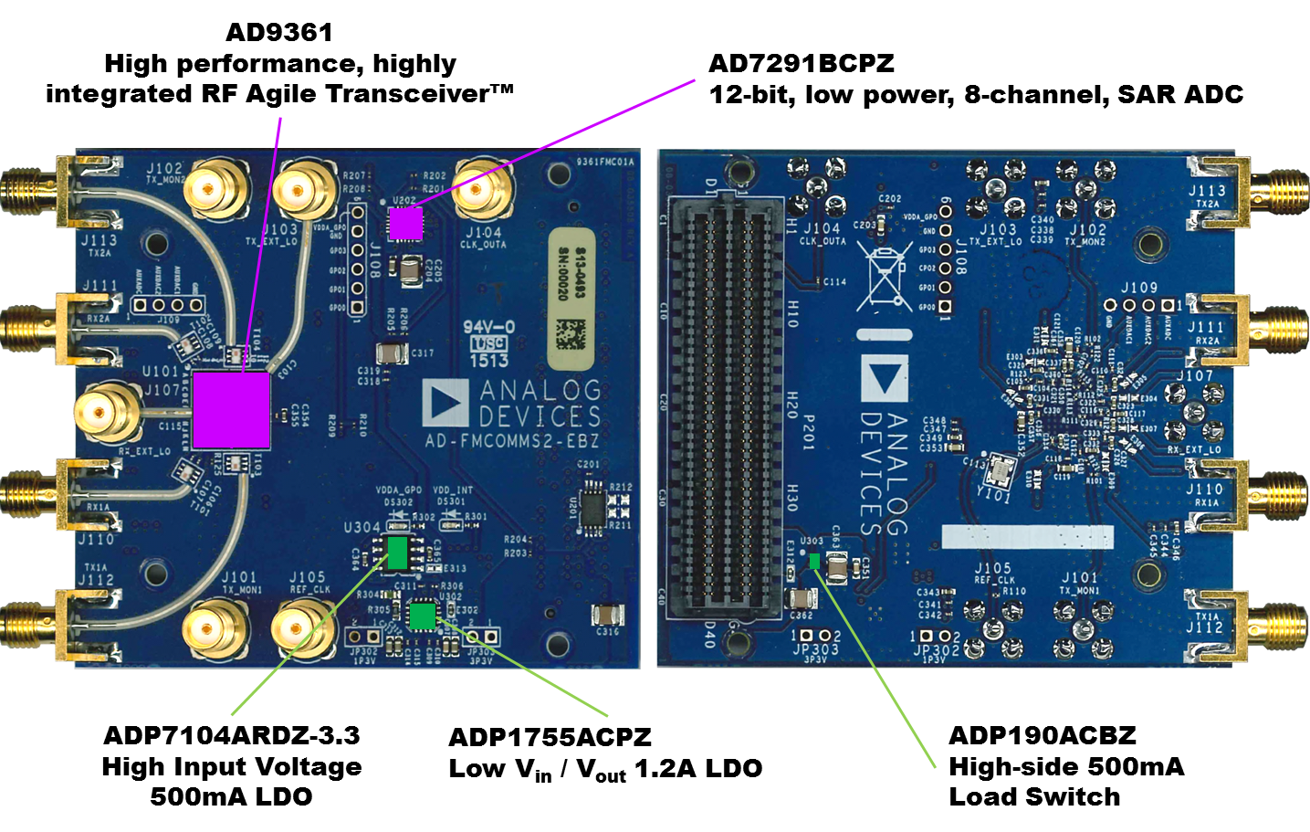
Hardware configuration
The AD-FMCOMMS2-EBZ board uses the Johanson Technology’s 2450BL15B050E 2.45 GHz Balun, rated for an operating frequency of 2400~2500 MHz. If you want to evaluate the part outside of this frequency range, an alternative balun should be installed.
Power supply
The board receives all the power from the FPGA carrier board through the FMC connector.
Key components:
Low dropout, linear regulator, 1.2A, 1.6 to 3.6V |
|
High Efficiency, Step-Down, DC-to-DC Regulator, 6.5V, 4A |
The AD-FMCOMMS2-EBZ (AD9361) assumes a VDD_INTERFACE voltage between 1.71 V and 2.625 V (1.8 to 2.5 +/- 5%), so on your FPGA carrier board, you should ensure that VADJ is between these levels. Setting things to 3.3 V will damage the part.
Schematic, PCB Layout, Bill of Materials
Note
This is the latest and greatest Rev “E” of this board. Note that the Baluns on the Rev C board (T101-T104) are Johanson Technology’s 2450BL15B050E 2.45 GHz Balun. This balun is rated for an operating frequency of 2400~2500 MHz. If you want to evaluate the part outside of this frequency range, an alternative balun should be installed. The test results were taken using the Johanson Technology’s 2450BL15B050E balun.
AD-FMCOMMS2-EBZ Design & Integration Files
Schematic
PCB Layout
Bill of Materials
The Epson crystal used on this board, has the generic part number “TSX-3225 40.0000MHZ” - however, the generic part number does not have the specifications needed to meet the AD9361 datasheet specs. ADI has worked with Epson to provide a tighter tolerance part, which can be ordered as the “OUTD-2B-0166” or “X1E000021036701” (either part number will work, depending on which system your Epson contact/distributor has) which meets the requirements that the AD9361 demands.
Allegro Project (Get the Allegro FREE Physical Viewer; you need 16.5 or higher).
Board outline and dimensions
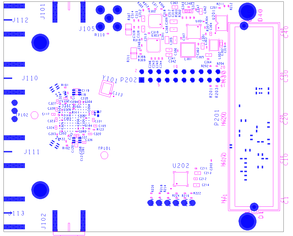
For those that don’t want to load up the Allegro viewer, here is a basic outline/component placements of the board. While this board does meet parts of the VITA-57.1 (FMC) specifications, there are many things it violates, and is not designed to be a form/fit/function board.
The FMC cutout for the bezel is missing (so we could space the SMA connectors out as far as possible, and achieve maximum isolation between the channels).
The mounting holes near the end of the board with the connectors are also in the wrong place (so it didn’t affect the RF path between the connectors and the AD9361).
The FMC height specification on the top side of the board is violated to put some 90 degree SMA connectors.

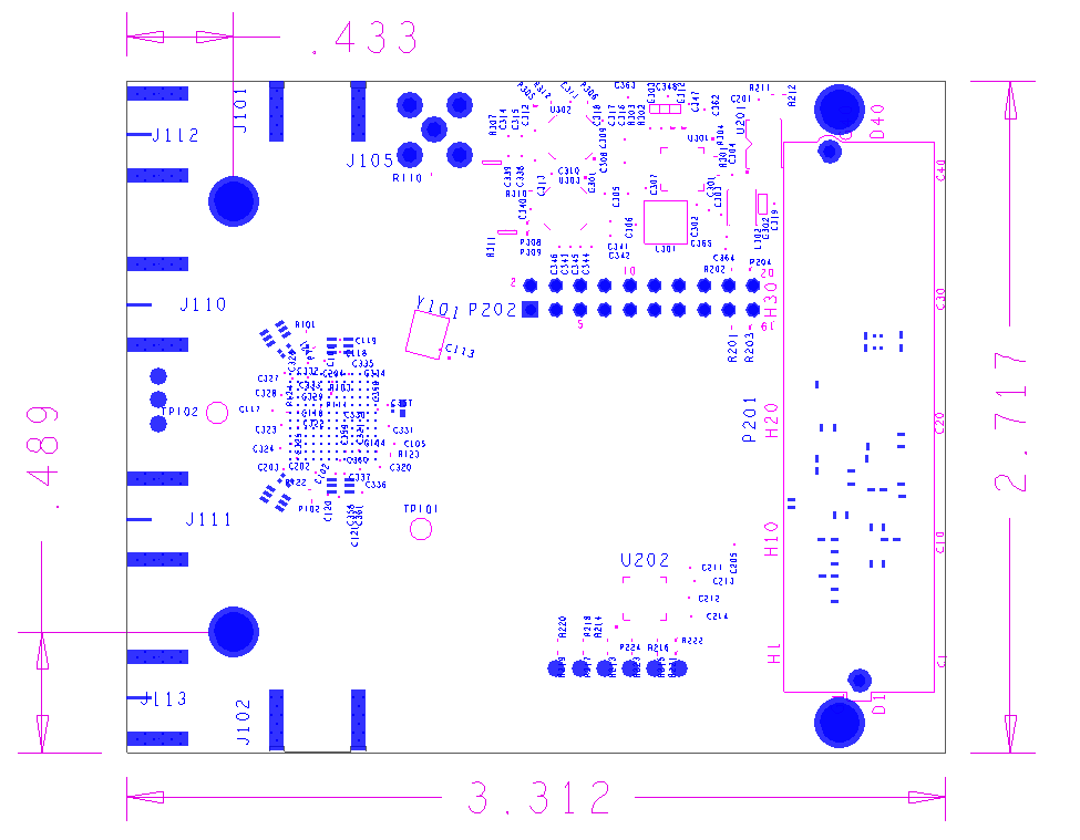
The size of the board (not including the SMA connectors, which project beyond the edge of the board) is 73.3 mm x 69 mm. This is under the FMC specifications of 84 mm x 69 mm. The mounting holes are not compliant with the FMC standard, and are shown below.
PCB layer stackup
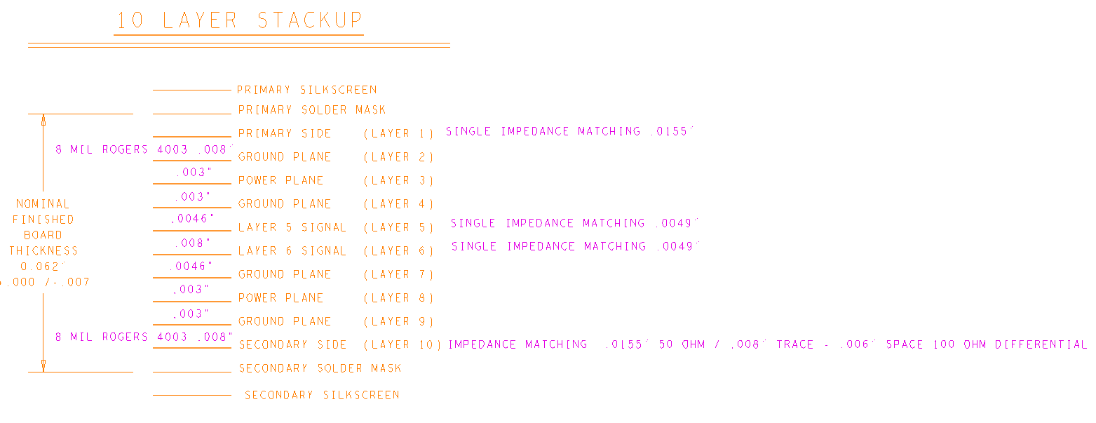
The AD-FMCOMMS2-EBZ is a 10 layer board.
Design Cross Section
Subclass Name |
Type |
Material |
Thickness (MIL) |
Conductivity (mho/cm) |
Dielectric Constant |
Loss Tangent |
Shield |
Width (MIL) |
|---|---|---|---|---|---|---|---|---|
SURFACE |
AIR |
0 |
1 |
0 |
||||
TOP |
CONDUCTOR |
COPPER |
2.025 |
595900 |
1 |
0 |
8.00 |
|
DIELECTRIC |
FR-4 |
8 |
0 |
3.38 |
0.035 |
|||
L2_GND |
PLANE |
COPPER |
1.35 |
595900 |
1 |
0.035 |
Y |
|
DIELECTRIC |
BT_EPOXY |
3 |
0 |
4.10 |
0.02 |
|||
L3_PWR |
PLANE |
COPPER |
1.35 |
595900 |
1 |
0.035 |
Y |
|
DIELECTRIC |
FR-4 |
3 |
0 |
4.10 |
0.035 |
|||
L4_GND |
PLANE |
COPPER |
1.35 |
595900 |
1 |
0.035 |
Y |
|
DIELECTRIC |
BT_EPOXY |
4.60 |
0 |
4.10 |
0.02 |
|||
L5_SIG |
CONDUCTOR |
COPPER |
1.35 |
595900 |
1 |
0.035 |
3.80 |
|
DIELECTRIC |
FR-4 |
8 |
0 |
4.10 |
0.035 |
|||
L6_SIG |
CONDUCTOR |
COPPER |
1.35 |
595900 |
1 |
0.035 |
3.80 |
|
DIELECTRIC |
BT_EPOXY |
4.60 |
0 |
4.10 |
0.02 |
|||
L7_GND |
PLANE |
COPPER |
1.35 |
595900 |
1 |
0.035 |
Y |
|
DIELECTRIC |
FR-4 |
3 |
0 |
4.10 |
0.035 |
|||
L8_PWR |
PLANE |
COPPER |
1.35 |
595900 |
1 |
0.035 |
Y |
|
DIELECTRIC |
BT_EPOXY |
3 |
0 |
4.10 |
0.02 |
|||
L9_GND |
PLANE |
COPPER |
1.35 |
595900 |
1 |
0.035 |
Y |
|
DIELECTRIC |
FR-4 |
8 |
0 |
3.38 |
0.035 |
|||
BOTTOM |
CONDUCTOR |
COPPER |
2.025 |
595900 |
1 |
0 |
8.00 |
|
SURFACE |
AIR |
0 |
1 |
0 |