AD-FMCOMMS2-EBZ
2x2 MIMO RF Agile Transceiver™, 70 MHz to 6.0 GHz.
Overview
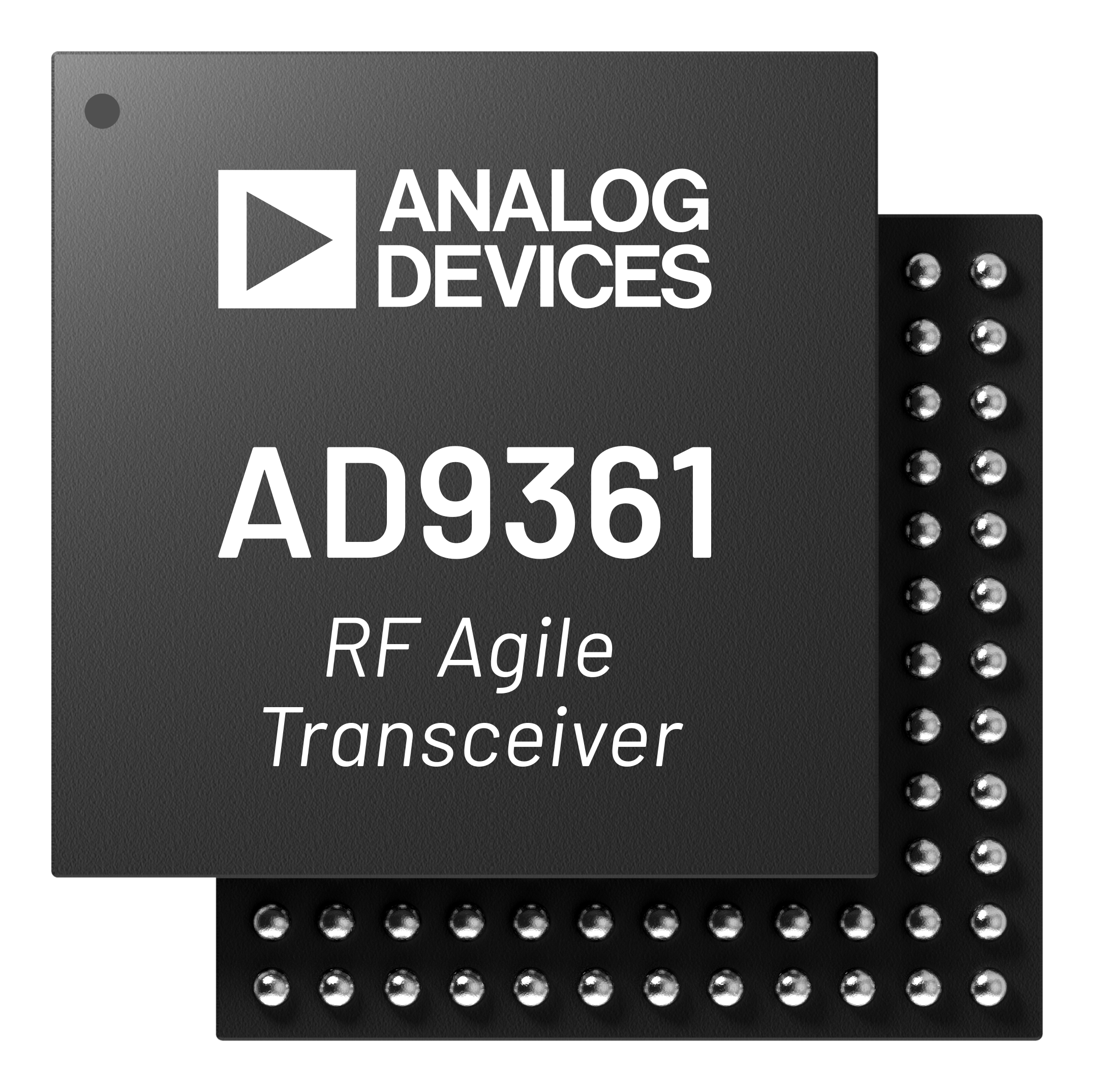
The EVAL-AD-FMCOMMS2 is an FMC board for the AD9361 (design package), a highly integrated RF Agile Transceiver™. While the complete chip level design package can be found on the ADI web site, information on the card, and how to use it, the design package that surrounds it, and the software which can make it work, can be found here.
The purpose of the AD-FMCOMMS2-EBZ is to provide an RF platform which shows maximum performance of the AD9361. It’s expected that the RF performance of this platform can meet the datasheet specifications without issues at 2.4 GHz, and not much anywhere else. This is due to the external Johanson Technology’s 2450BL15B050E 2.45 GHz Balun that is on the board. This balun is rated for an operating frequency of 2400~2500 MHz.
This platform is primarily for hardware / RF investigation and bring up of various waveforms from a RF team before their custom hardware is complete, where they want to see waveforms at their frequency of interest, and are not afraid of changing out the balun if necessary. (Have a look in the Configuration sections).
The AD-FMCOMMS2-EBZ board is very similar to the AD-FMCOMMS3-EBZ board with only one exception, the RX/TX RF differential to single ended balun/transformer. The AD-FMCOMMS3-EBZ is more targeted for wider tuning range applications, that is why we use the TCM1-63AX+ from Mini Circuits as the RF transformer of choice. We affectionately call the FMCOMMS3-EBZ the “Software Engineers” platform, and the FMCOMMS2-EBZ, the “RF Engineers” platform to denote the difference.
Features:
2x2 MIMO transceiver with integrated 12-bit DACs and ADCs
Tunable frequency range: 70 MHz to 6.0 GHz
Adjustable channel bandwidth: 200 kHz to 56 MHz
Johanson Technology 2.45 GHz balun (optimized for 2.4 GHz)
FMC-LPC system board connector
On-board power solution
Applications:
Software-defined radio (SDR)
Point-to-point communication
Wireless LAN (2.4 GHz)
LTE/3G femtocell base stations
General-purpose radio experimentation

Recommendations
People who follow the flow that is outlined, have a much better experience with things. However, like many things, documentation is never as complete as it should be. If you have any questions, check the Help and Support page.
To better understand the AD9361, we recommend to use the EVAL-AD-FMCOMMS2 evaluation board.
Table of contents
Hardware: This provides a brief description of the board by itself, and is a good reference for those who want to understand a little more about the board. If you just want to use the board, you can skip this section, and come back to it when you want to incorporate the AD9361 into your product.
Use the board to better understand the AD9361
Linux Applications
Push custom data into/out of the AD9361
Design with the AD9361
Simulation
Hardware in the Loop / How to design your own custom BaseBand
MATLAB/Simulink Examples
FM Radio/Tuner (listen to FM signals on the HDMI monitor)
Targeting
Complete Workflow
Design a custom AD9361 based platform
Linux software
No-OS Software
HDL reference design which you must use in your FPGA.
Additional Documentation about SDR Signal Chains
Videos
Introduction to the AD9361
Introduction to the AD9361 based ecosystem
Digital Filter Wizard for the AD9361
Software Defined Radio using the Linux IIO Framework
ADI Articles
Four Quick Steps to Production: Using Model-Based Design for Software-Defined Radio
MathWorks Webinars
Warning
All the products described on this page include ESD (electrostatic discharge) sensitive devices. Electrostatic charges as high as 4000V readily accumulate on the human body or test equipment and can discharge without detection. Although the boards feature ESD protection circuitry, permanent damage may occur on devices subjected to high-energy electrostatic discharges. Therefore, proper ESD precautions are recommended to avoid performance degradation or loss of functionality. This includes removing static charge on external equipment, cables, or antennas before connecting to the device.
Help and support
Please go to Help and Support page.