CN0549 CbM Pelican Kit
This page describes how to create a standalone CN0549 CbM kit that can travel with you anywhere. The following steps assume that you have already completed the instructions for assembling the CN0549 system. If you have not configured the hardware or software, please visit the CN0549 User Guide before continuing with this kit.
Required Materials
Hardware:
Cabling the CN0532 to the CN0540
Twisted pair set of wires cut to the desired length
USB OTG (micro USB to USB Type A female USB 2.0 compatible)
HDMI cable (male to male) (2 ft length)
USB Wireless Keyboard + Mouse (must be less than 11.5 inches wide and 4.5 inches tall)
Software:
Creating a Pelican Kit
The following sections describe how to integrate the CN0549 into a single Pelican case for easy use, transport, and shipping. These instructions assume that you have already completed the CN0549 hardware, software, and system setup. If you have not configured the hardware or software, please visit the CN0549 User Guide.
Mount the HDMI Monitor
Mount the HDMI monitor inside the Pelican 1400 case on the lid side. To do this, you must cut into the foam provided in the case.
Align the edge of the monitor with the left-hand side of the case as shown in the picture. This will leave about 2 inches of foam on the right-hand side.
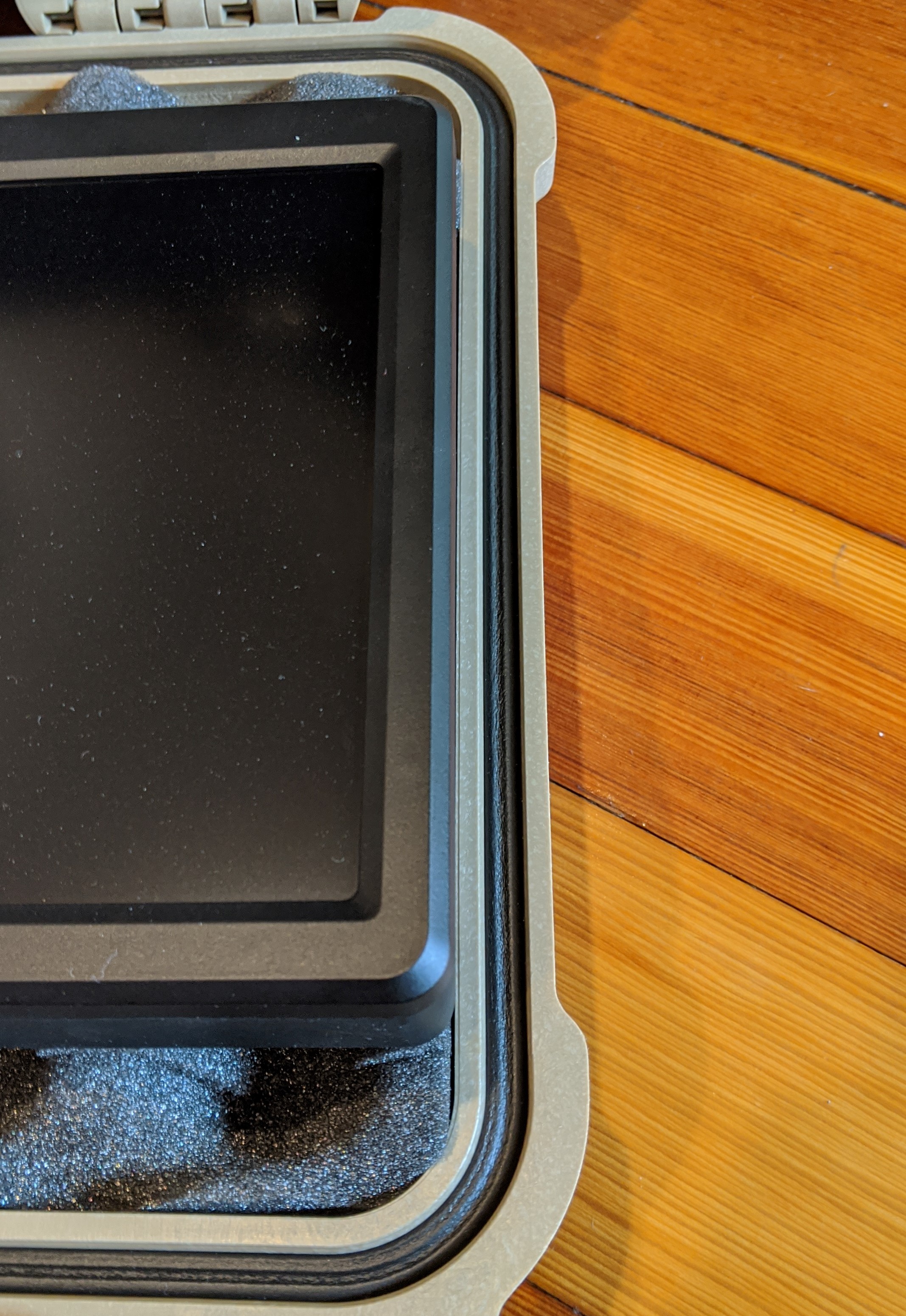
Position the monitor approximately 1 inch from the top and 2 inches from the bottom edge of the foam.
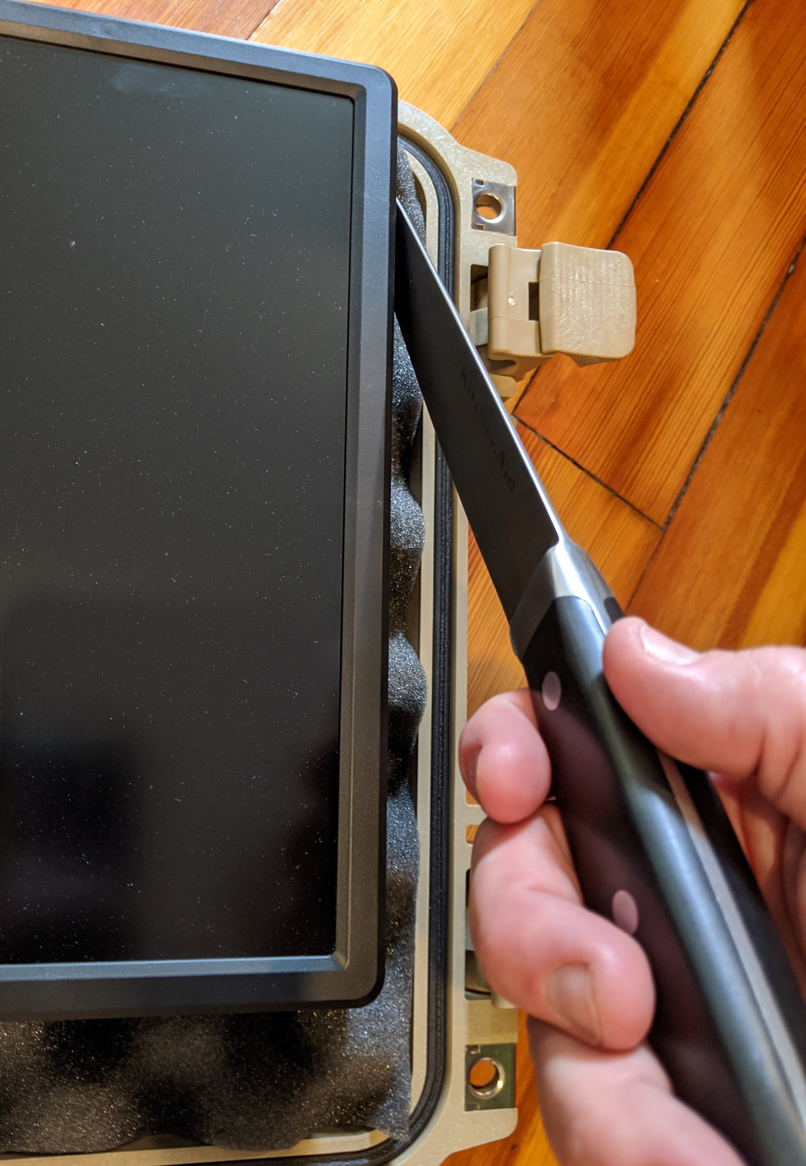
Cut around the outline of the monitor using a very sharp knife.
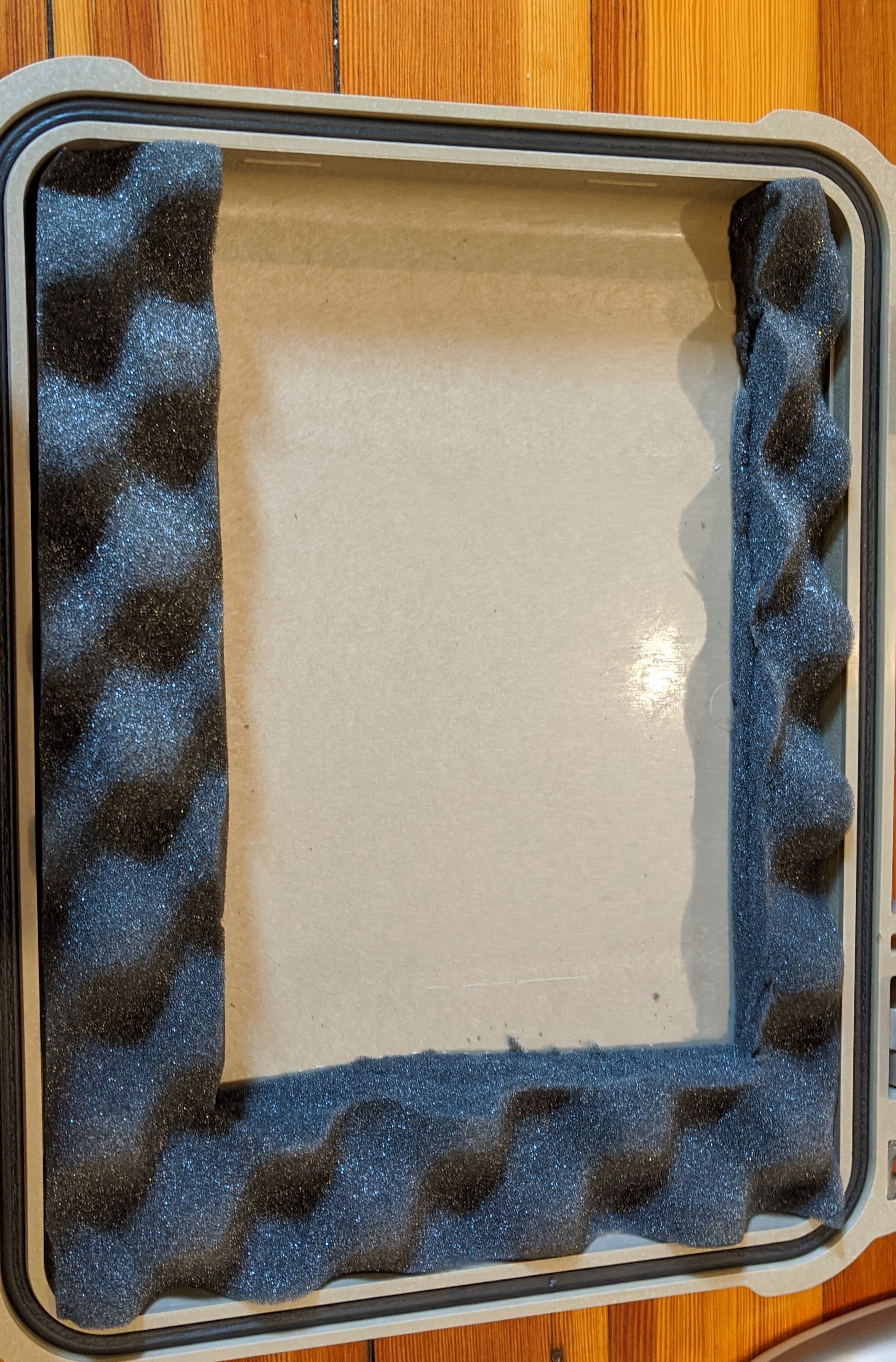
After cutting out the monitor opening, it should look like this.
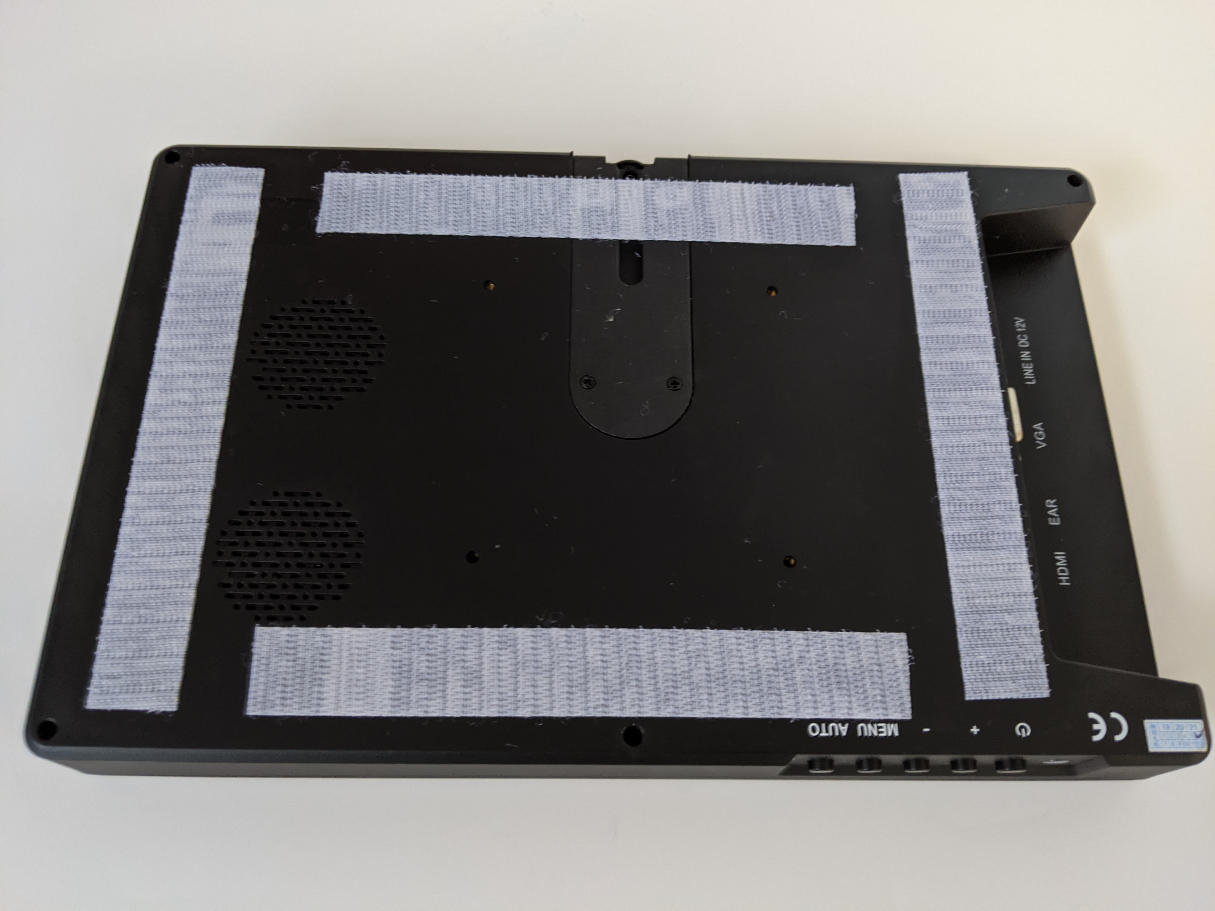
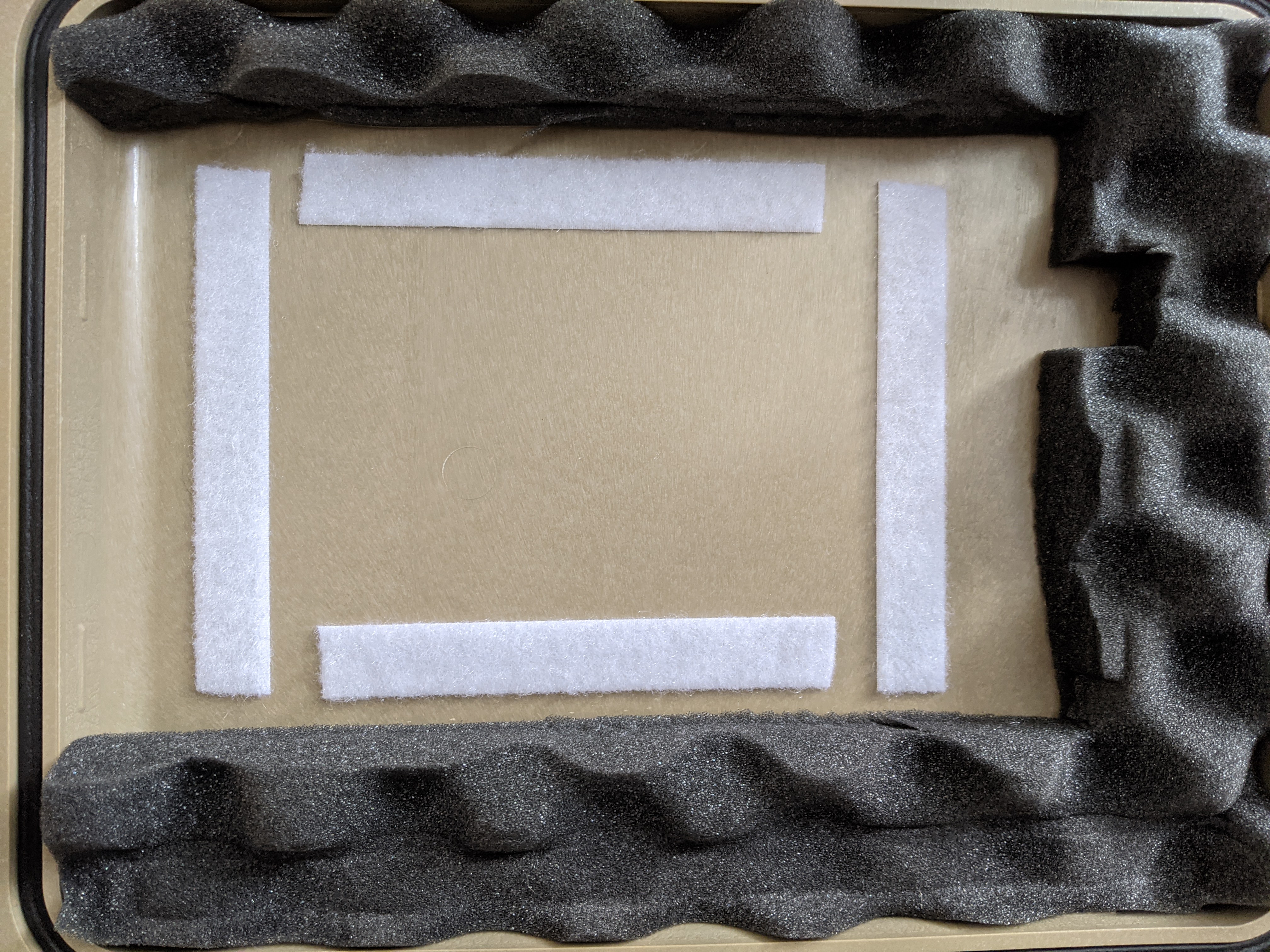
After cutting the monitor placement, adhere it to the Pelican case lid. Cut 4 Velcro strips and place them on the back of the monitor as shown below. Do not cover venting holes or other important access points.
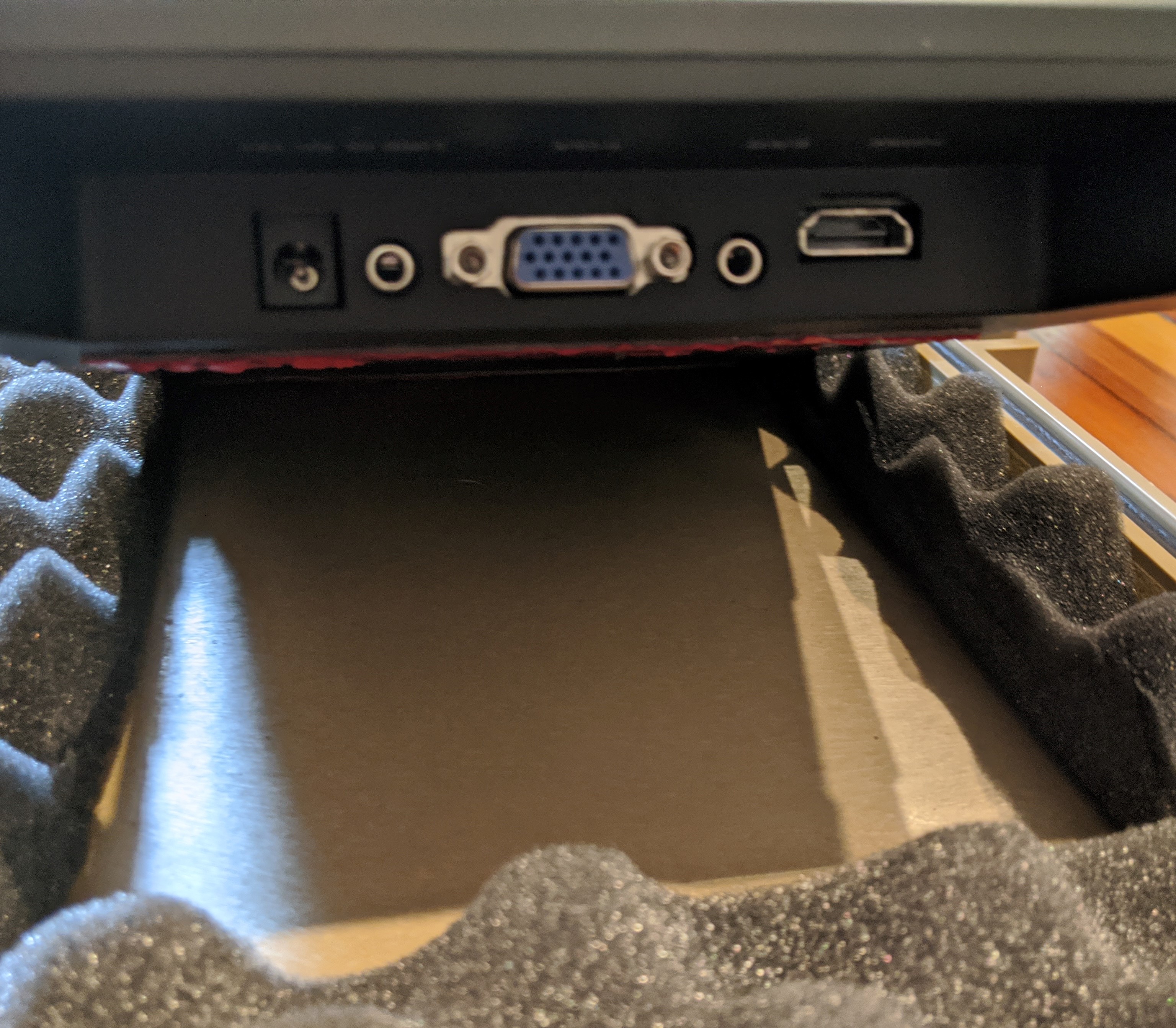
On the right-hand side, you will see the connector panel. Connect the HDMI cable and the DC barrel jack to the monitor.
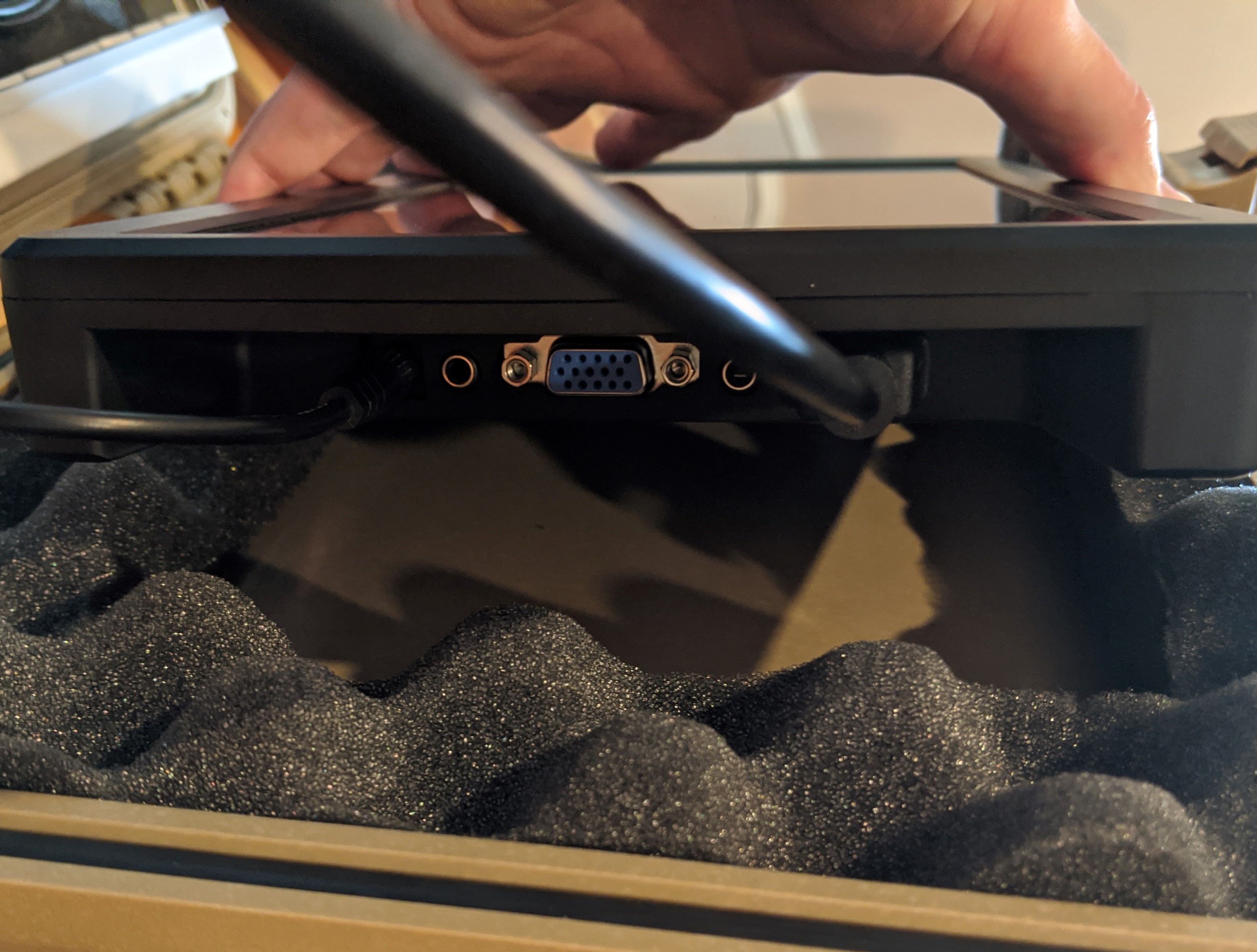
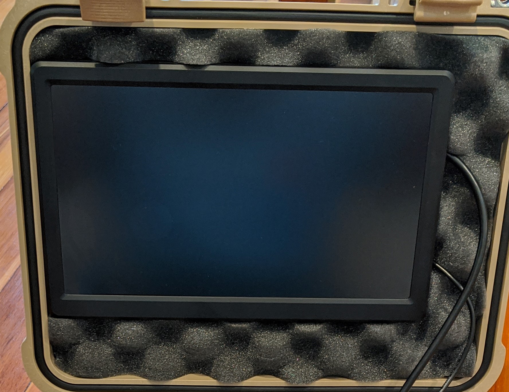
Use the monitor to align the other side of the Velcro with the case. Remove the adhesive backing and insert the monitor into the Pelican case lid. Apply light pressure to ensure a stable connection, but not so much as to damage the screen.
Cutting the Foam
All other items needed to run the demo must fit inside this Pelican case. There are several possible layouts, but the following steps describe an optimal arrangement.
Begin by preparing the foam. The Pelican case includes foam that is perforated into 0.5 inch squares. This allows you to customize the layout and fit the components in the case.
Lift the foam block from the main basin of the Pelican case and remove the thin, single piece of foam located at the bottom. Place it aside for later use.
When viewed from the top, the foam has an outer non-perforated layer and an inner perforated grid.
Remove all the foam pieces shown in blue using the grid pattern outlined below. Note that the outer edge is non-perforated.
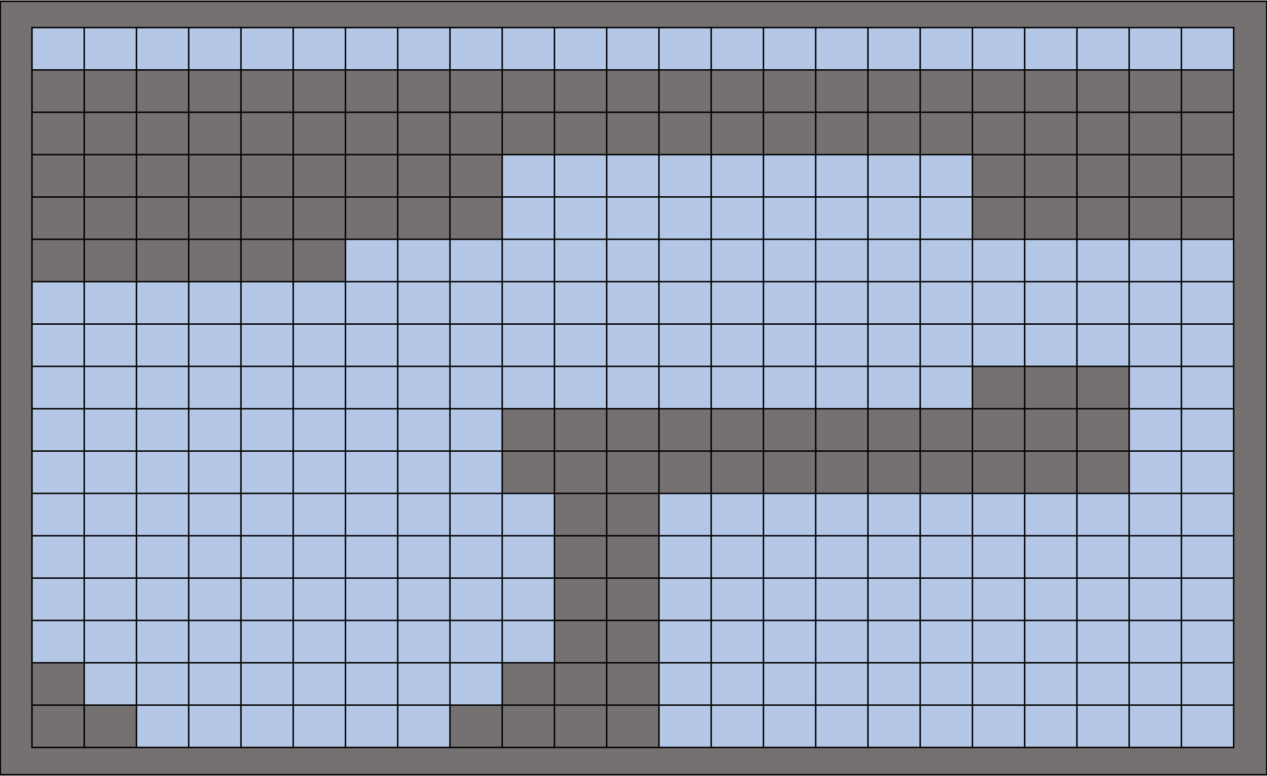
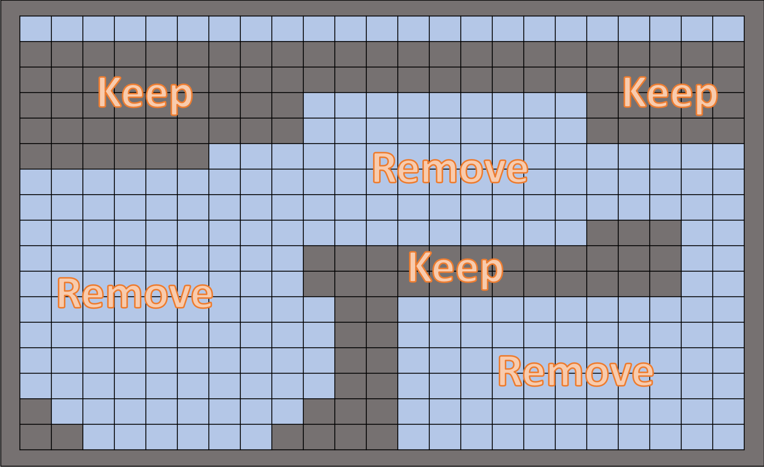
Important
Remove the foam in 5 or 6 large sections. You will need this foam later as padding for the bottom of the case.
Create padding using the foam removed in the previous steps.
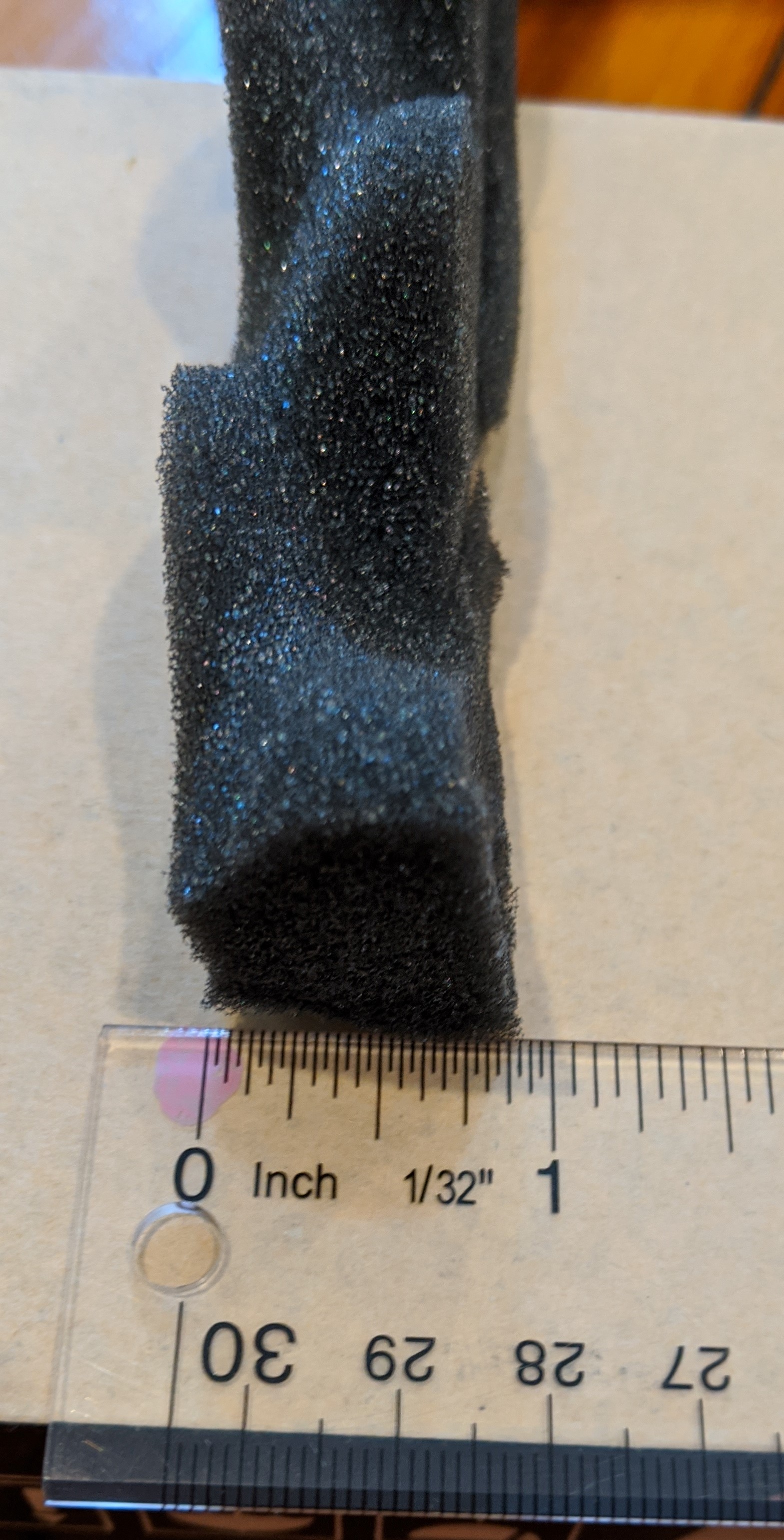
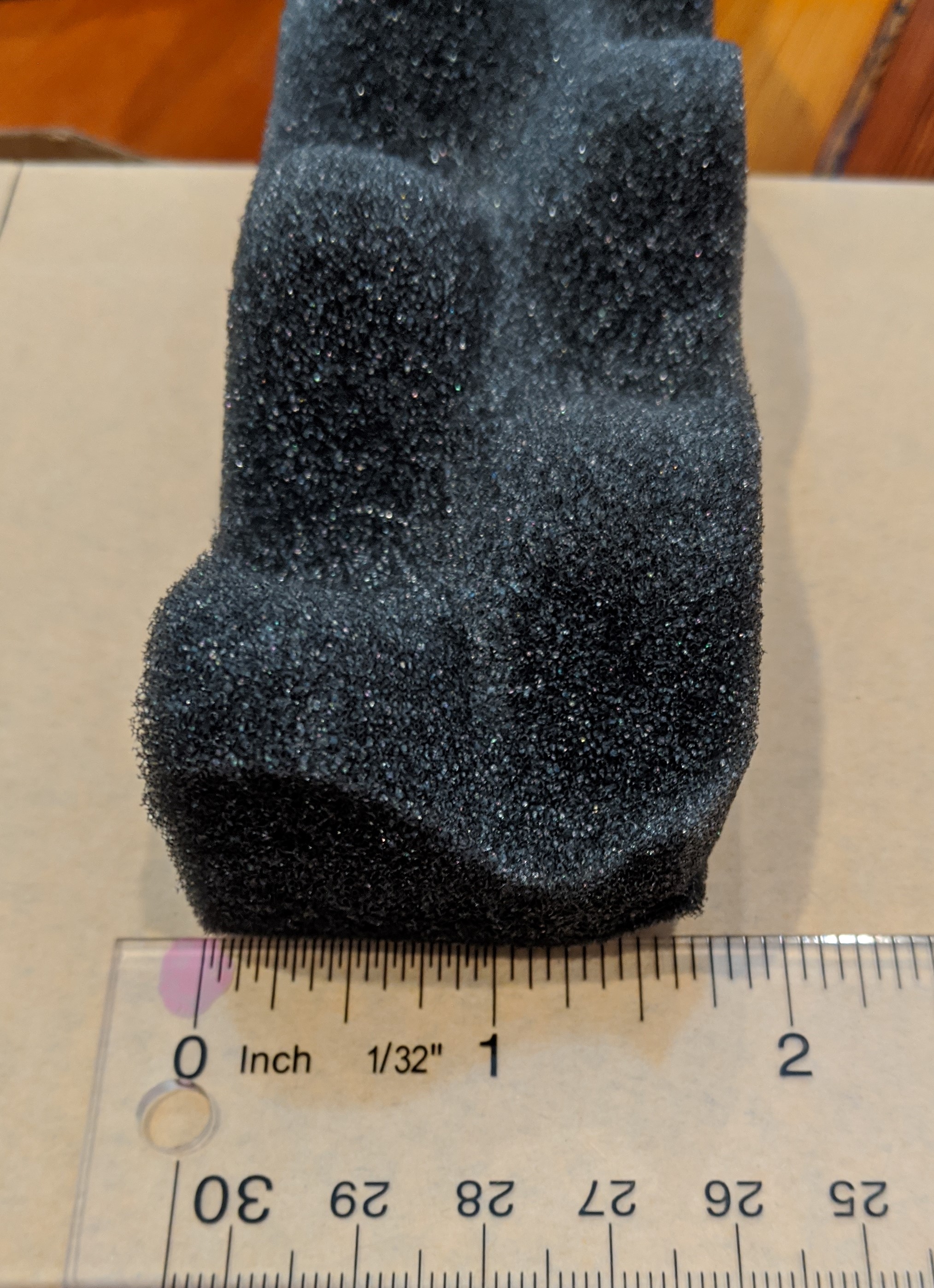
There are 3 different padding heights, divided by equipment section.
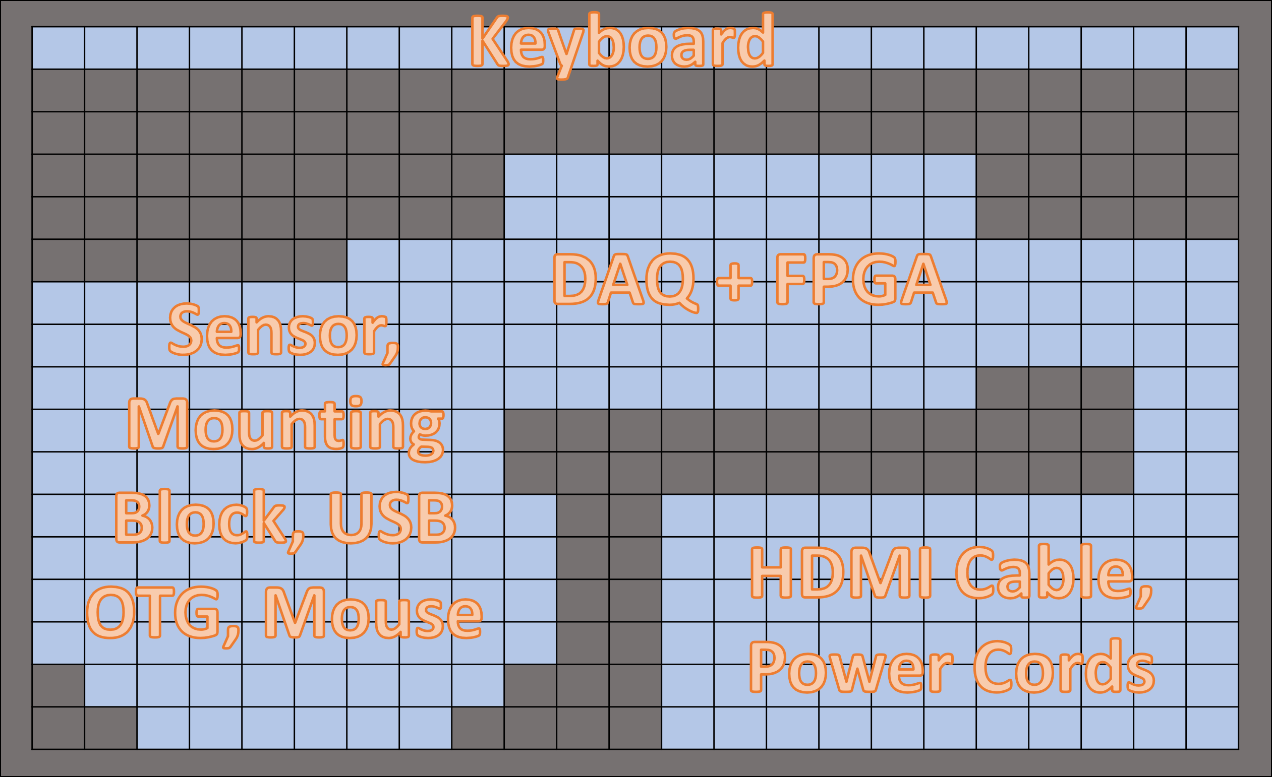
Keyboard == No padding
HDMI and power cords == 1 inch of padding
DAQ, FPGA, sensor, mounting block, USB OTG, mouse == 1.5 inches of padding
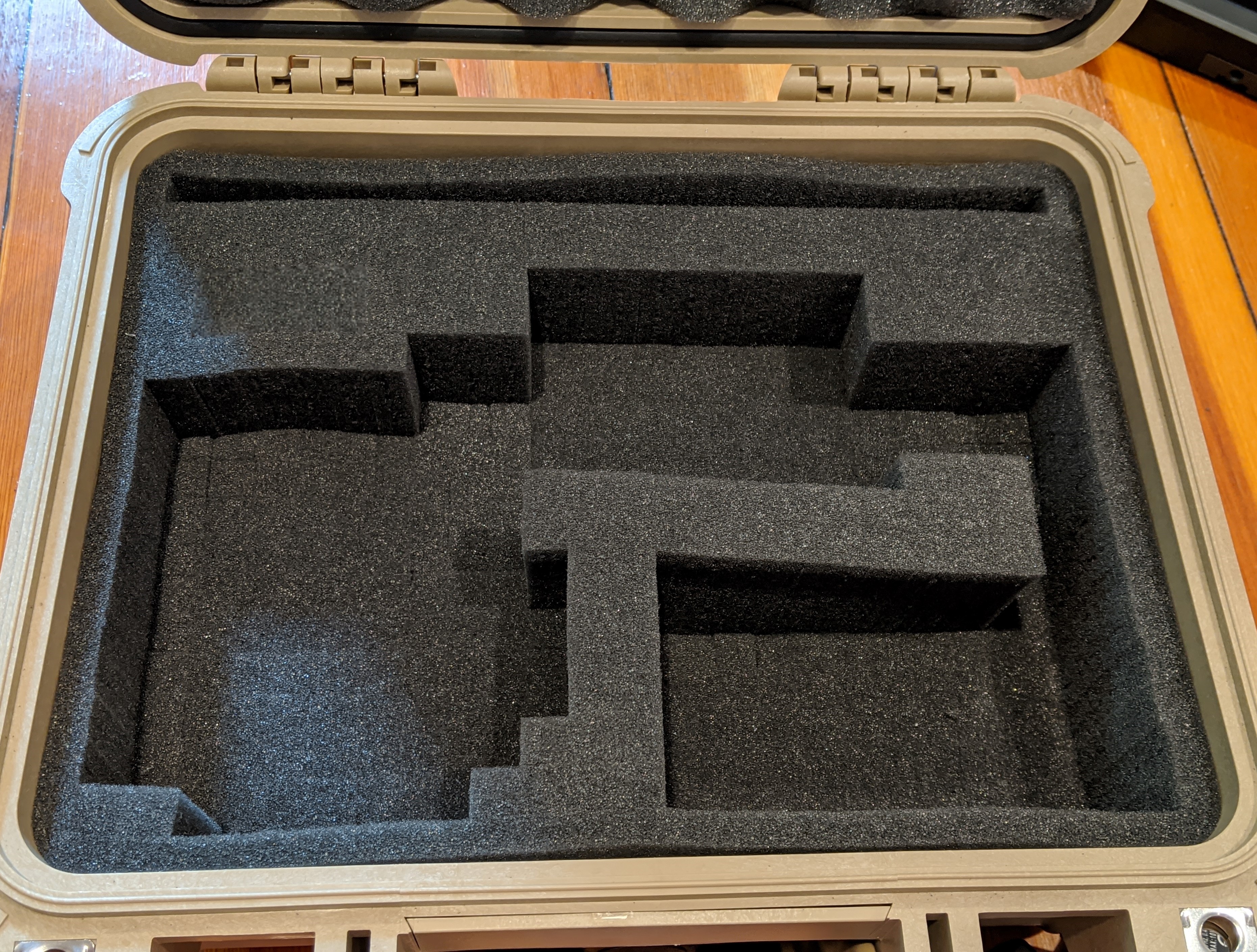
After cutting the padding, reinsert it into the foam cutout. If you follow these steps correctly, your Pelican case should look like this.
Equipping the Pelican ase
Begin placing the required items into your Pelican case for standalone operation.
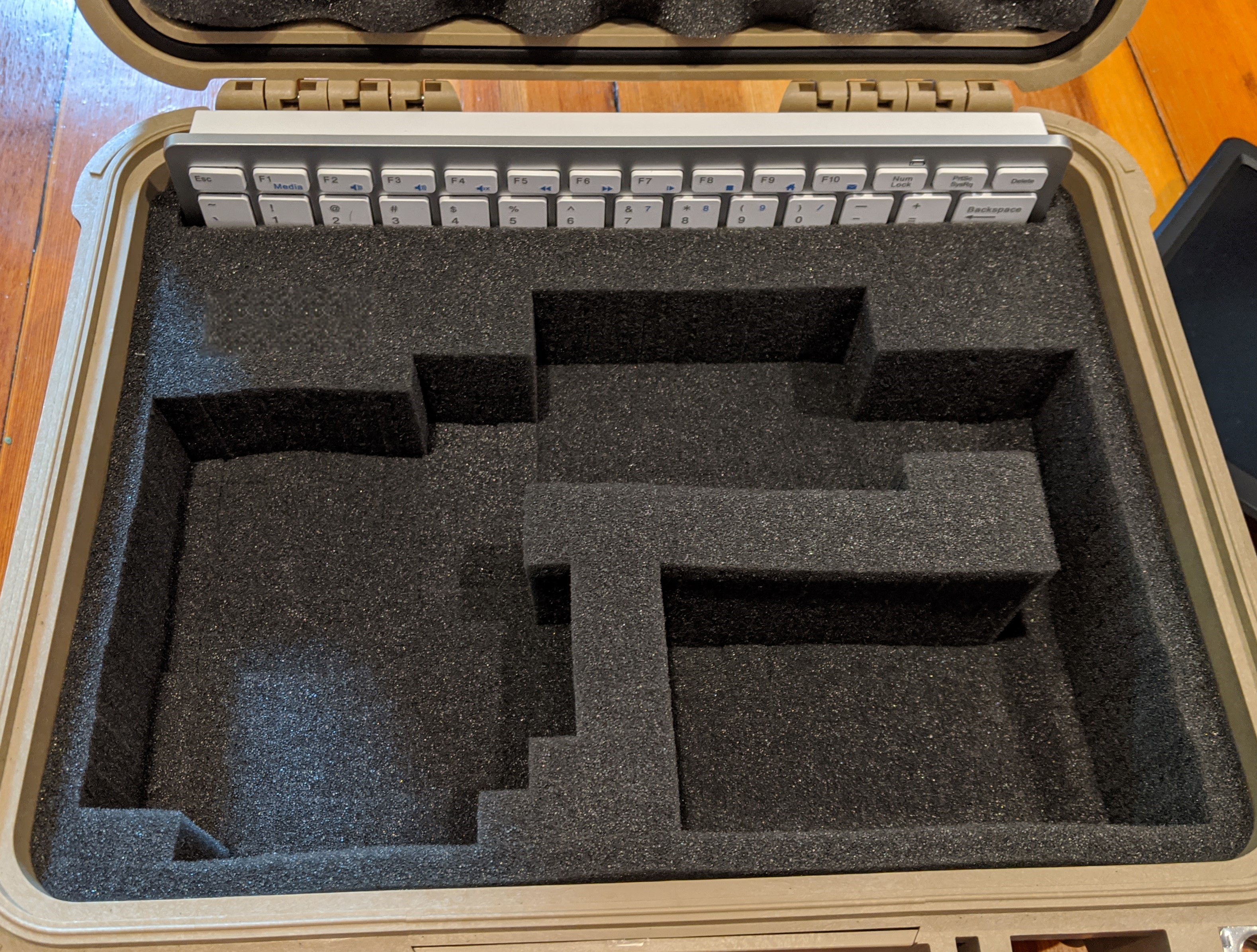
The keyboard should be the first item placed into the assigned foam slots.
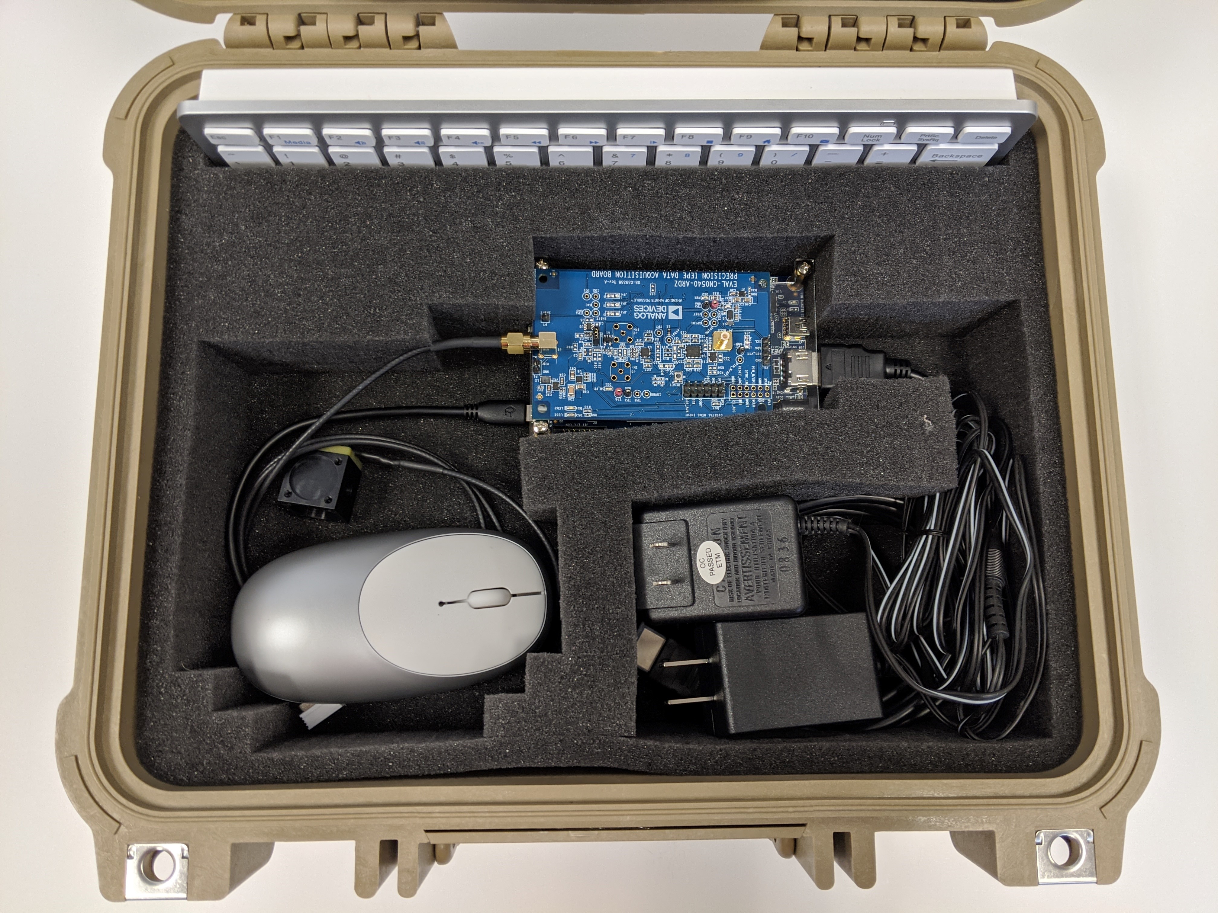
Next, connect the DE10-Nano to the CN0540, CN0532, mounting block, SMA cable, and USB OTG adapter, then place them in their assigned positions.
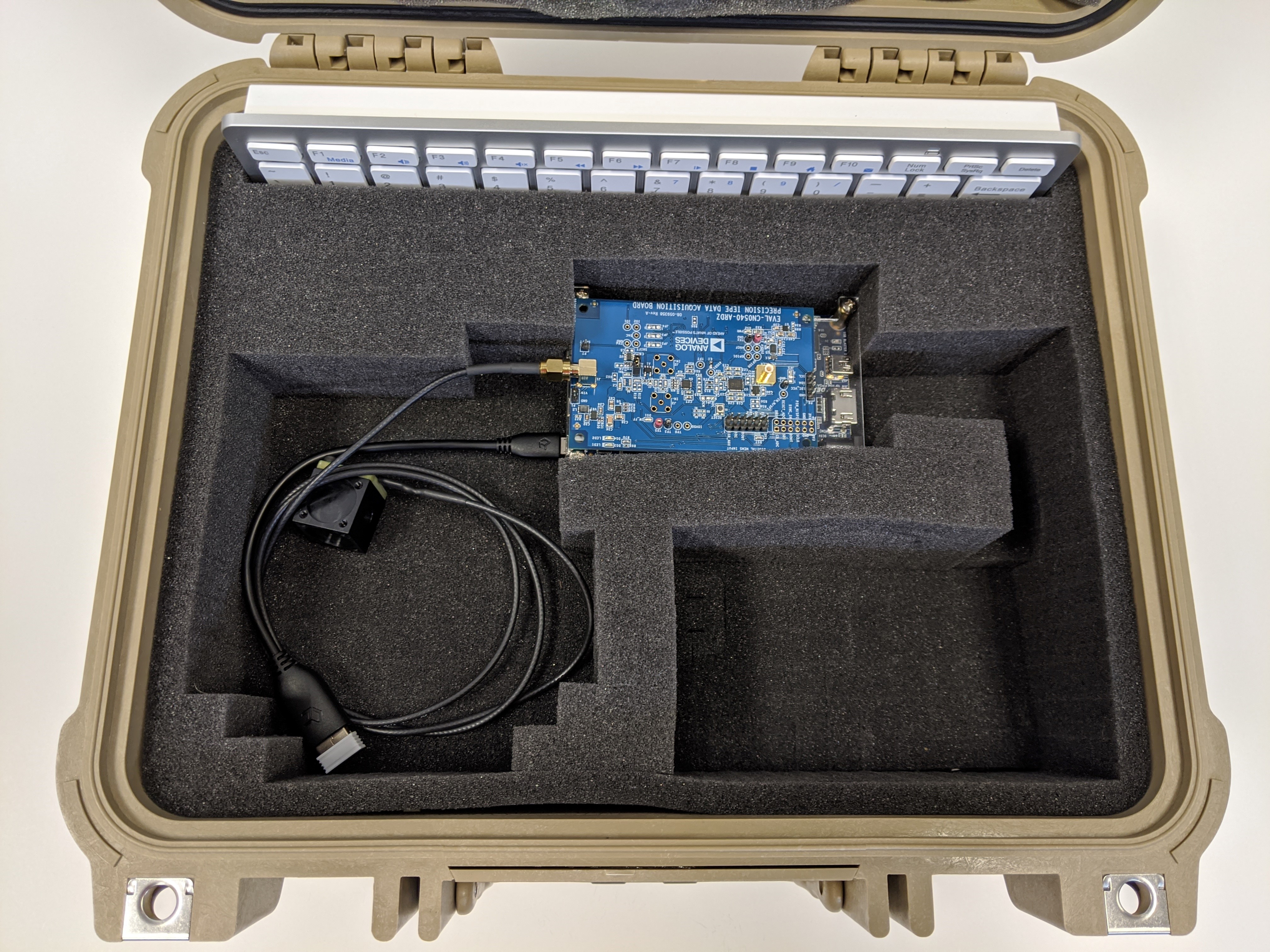
Coil the wires for the CN0532, mounting block, SMA cable, and USB OTG cable neatly so they fit into the correct position. Place the wireless mouse on top of these.
Attach the HDMI cable and the DC barrel jack to the DE10-Nano. Coil the cables so that everything fits into its assigned position.
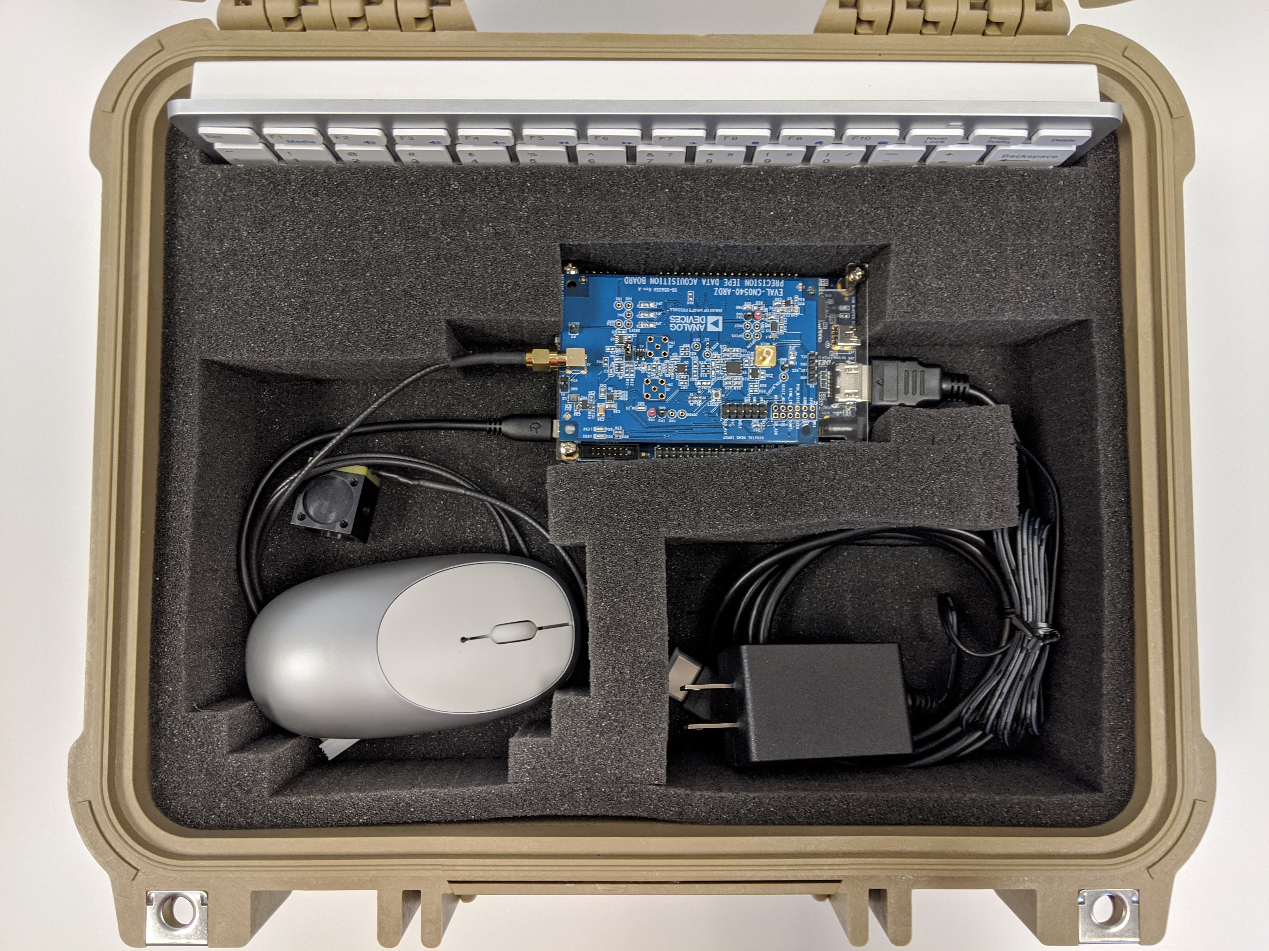
When everything is complete, the main basin of the Pelican case should look like this.
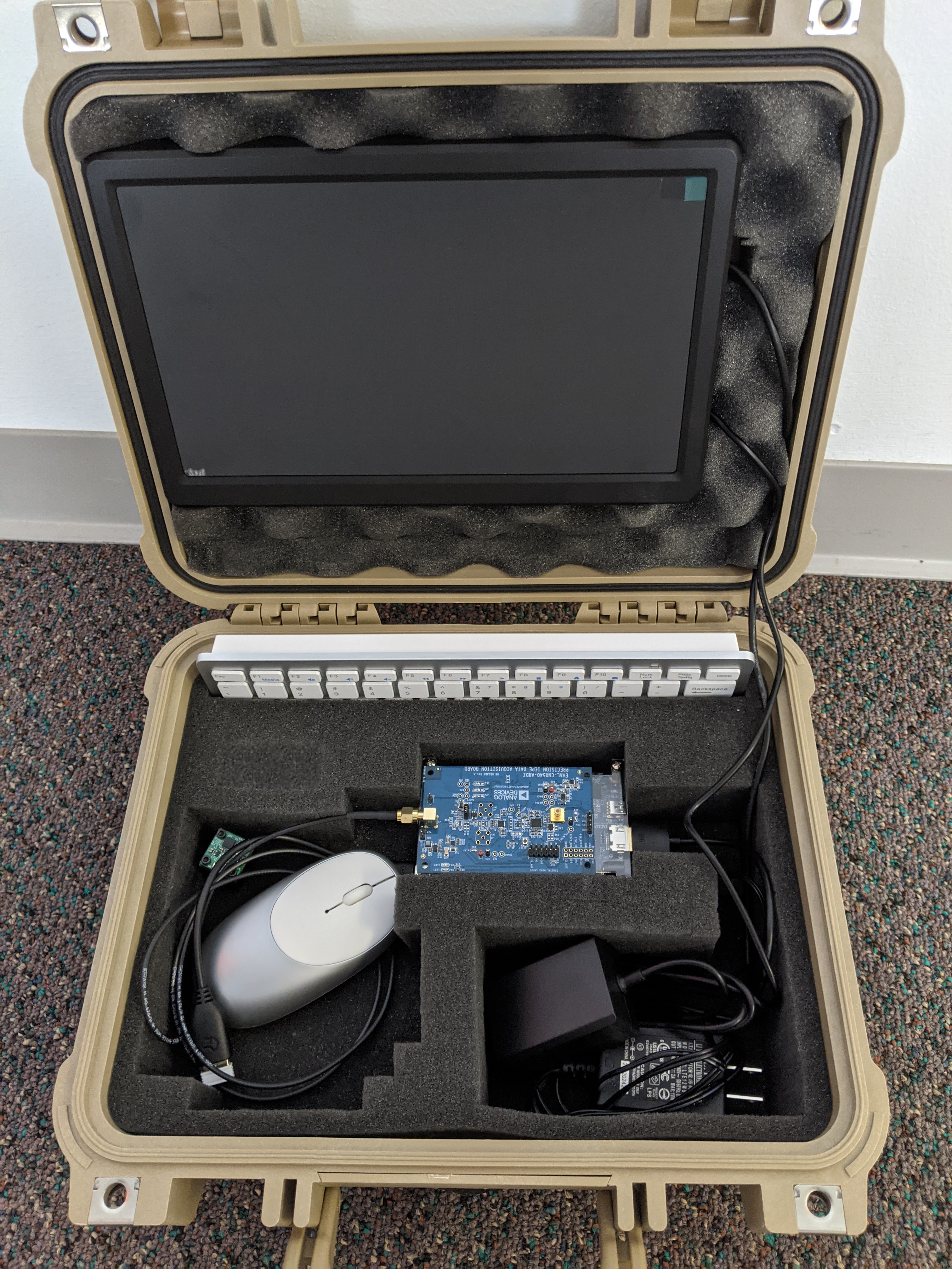
The entire open CN0549 case should look similar to this.
Before closing the lid, add the protective foam to prevent damage to the HDMI monitor.
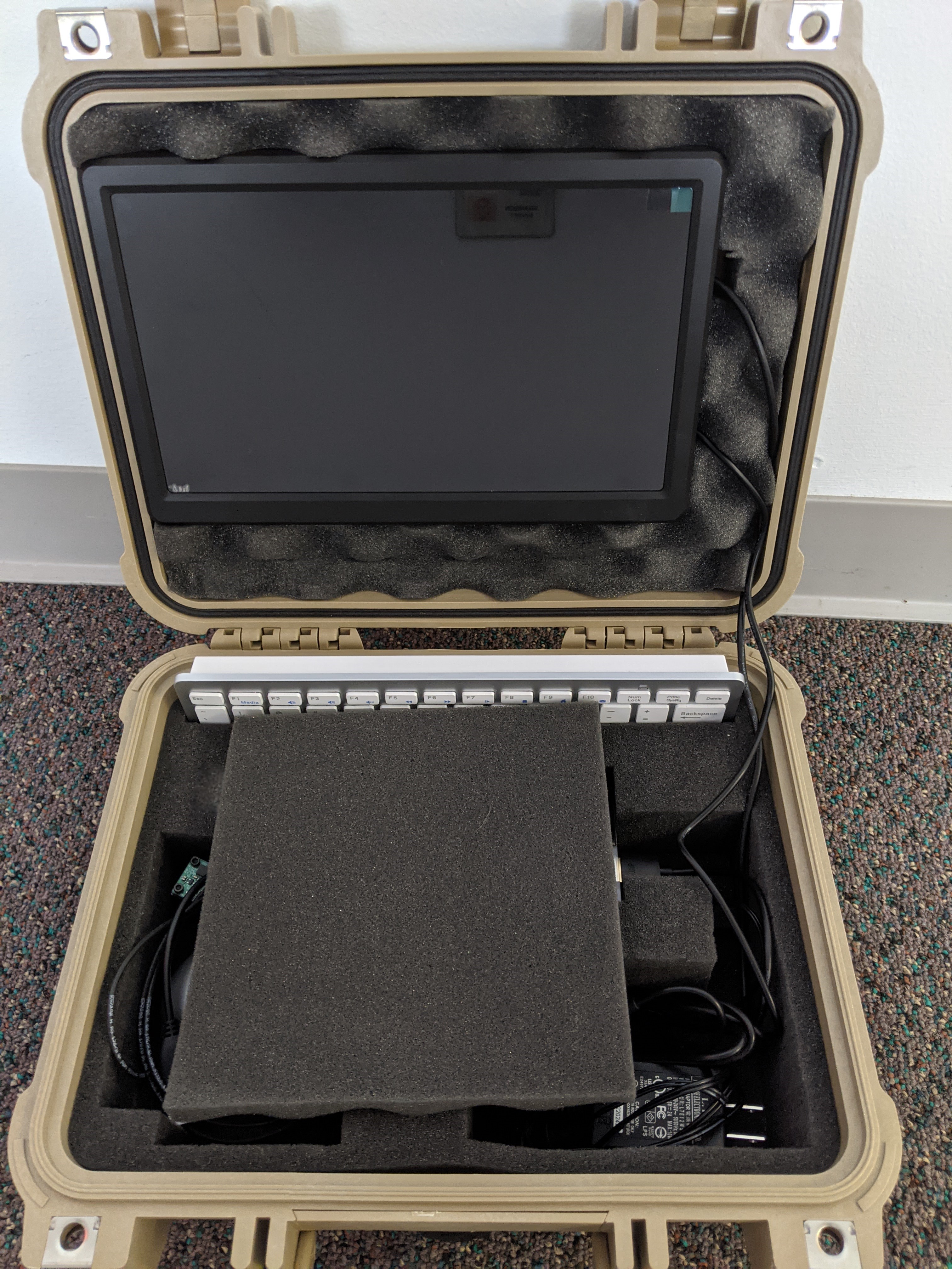
You are now ready to close the case and transport your setup.
End of Document