ZedBoard Quick start
This guide provides quick instructions on how to setup the ADV7511 HDMI transmitter on:
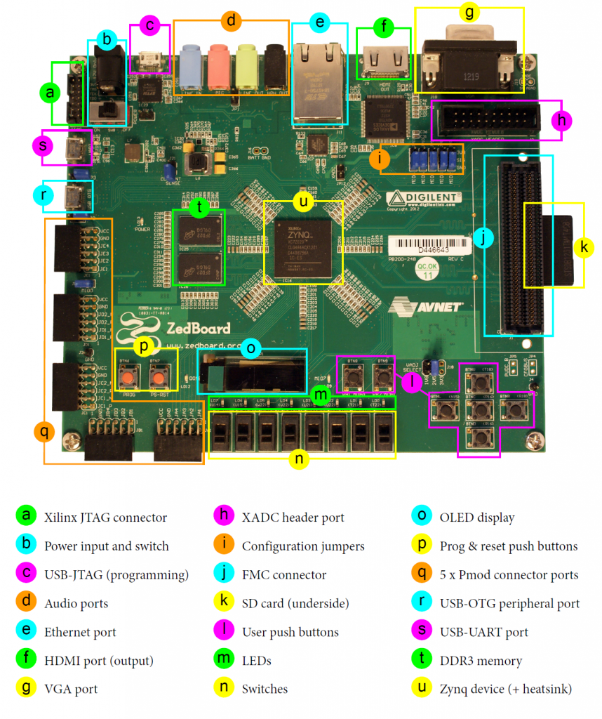
ZedBoard (Zynq-7000 SoC)
All the products described on this page include ESD (electrostatic discharge) sensitive devices. Electrostatic charges as high as 4000V readily accumulate on the human body or test equipment and can discharge without detection. Although the boards feature ESD protection circuitry, permanent damage may occur on devices subjected to high-energy electrostatic discharges. Therefore, proper ESD precautions are recommended to avoid performance degradation or loss of functionality. This includes removing static charge on external equipment, cables, or antennas before connecting to the device.
Using Linux as software
Necessary files
The following files are needed for the system to boot:
HDL boot image:
BOOT.BINLinux Kernel image:
uImageLinux device tree:
devicetree.dtb
They can either be taken from the SD card – already generated by us, or you can build them manually.
In the following sections, we explain how to take them from the SD card.
Instructions on how to manually build the boot files from source can be found here:
ADV7511 HDL reference design build documentation. More HDL build details at Build an HDL project.
Required Software
SD Card 16GB imaged with Kuiper (check out that guide on how to do it, then come back to this section)
A UART terminal (Putty/Tera Term/Minicom, etc.) with baud rate 115200 (8N1)
Required Hardware
ZedBoard and its power supply
SD card with at least 16GB of memory
Mini-USB cable (UART)
LAN cable (Ethernet)
HDMI Monitor
HDMI cable
(Optional) USB keyboard & mouse
More details as to why you need these, can be found at Prerequisites.
Testing
Creating the setup
Follow the steps in this order, to avoid damaging the components:
Insert SD card into the SD card socket on the ZED Board
Configure the ZED Board for SD card boot mode (Set the jumpers: JP7-JP11 need to be set for SD boot: JP7: 1-2, JP8: 2-3, JP9: 2-3, JP10: 2-3, JP11: 2-3)
Connect an HDMI cable between the ZED Board HDMI output port and the HDMI monitor
Plug-in an Ethernet cable from your router/switch to the Ethernet port on the FPGA board
Connect USB UART (Mini-USB) to your host PC
(Optional) Connect a USB keyboard and mouse via USB hub
Connect the power supply for the ZED Board
Turn on the HDMI monitor
Turn on the power switch on the ZED Board
Observe Kernel and serial console output messages on your terminal (use the first ttyUSB or COM port registered)
Useful commands for the serial terminal
The below commands are to be run in the serial terminal connected to the FPGA.
Login Information
user: analog password: analog
To find out the IP of the FPGA board, run the following command and take the IP specified at “eth0 inet”:
~$
ifconfig
To see the framebuffer device:
~$
ls /dev/fb*
To test the HDMI output with a color pattern:
~$
cat /dev/urandom > /dev/fb0
To check the current display mode:
~$
fbset
mode "1920x1080-60"
   # D: 148.500 MHz, H: 67.500 kHz, V: 60.000 Hz
   geometry 1920 1080 1920 1080 32
   timings 6734 148 88 36 4 44 5
   accel false
   rgba 8/16,8/8,8/0,8/24
endmode
To power off the system, run the following command, and wait for the final message to be printed, then power off the FPGA board from the switch as well.
~$
poweroff
To reboot the system, run:
~$
reboot
Important
Even though this is Linux, this is a persistent file system. Care should
be taken not to corrupt the file system – please shut down things, don’t
just turn off the power switch. Depending on your monitor, the standard
power off could be hiding. You can do this from the terminal as well with
sudo shutdown -h now or the above-mentioned command for powering
off.
Using no-OS as software
Necessary files
The following files are needed for the system to work:
HDL project files: projects/adv7511/zed
no-OS project: projects/adv7511
ADV7511 Transmitter Library: ADV7511 HDMI Transmitter Library
Instructions on how to build the boot files from source can be found here:
ADV7511 HDL reference design. More HDL build details at Build an HDL project.
no-OS build guide: No-OS Build Guide
Required Software
AMD Xilinx Vivado and Vitis (downloading Vitis from here will include Vivado as well)
An UART terminal (Putty/Tera Term/Minicom, etc.), Baud rate 115200 (8N1)
ADV7511 Transmitter Library (requires Wine on Linux)
Required Hardware
ZED Board and its power supply
HDMI Monitor
HDMI cable
2x Mini-USB cables, one for UART and one for JTAG
(Optional) USB keyboard & mouse
More details as to why you need these, can be found at Prerequisites.
Testing
Creating the setup
Follow the steps in this order, to avoid damaging the components:
Configure the ZED Board for JTAG boot mode (Set the jumpers: JP7-JP11 need to be set for JTAG boot: JP7: 1-2, JP8: 1-2, JP9: 1-2, JP10: 1-2, JP11: 1-2)
Connect an HDMI cable between the ZED Board HDMI output port and the HDMI monitor
Connect USB UART (Mini-USB) to your host PC
Connect USB JTAG (Mini-USB) to your host PC
Turn on the HDMI monitor
Turn on the power switch on the ZED Board
Observe console output messages on your terminal (use the first ttyUSB or COM port registered)
Building and Running the Software
Follow these steps to build and run the ADV7511 demo:
Download and install the ADV7511 HDMI Transmitter Library
On Linux: Use Wine to install the library
Extract the TX folder from the installation directory to the no-OS project:
From:
<installation folder>/Src/TX/To:
<no-OS repo>/projects/adv7511/TX/
Build the HDL project for ZED:
Follow the instructions at Build an HDL project
Generate the .xsa file
Copy the .xsa file to the no-OS project directory:
<no-OS repo>/projects/adv7511/
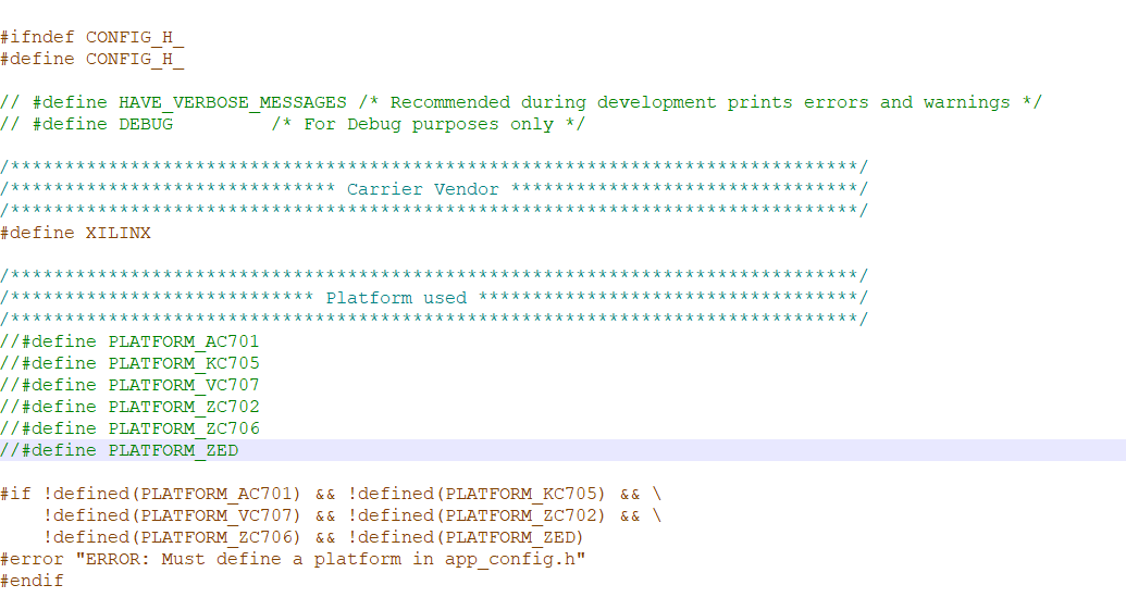
In the no-OS project, edit
src/app_config.h:Uncomment
#define PLATFORM_ZED
Build the no-OS project following the No-OS Build Guide
Program the FPGA and run the application through your IDE (Vitis)
Open your UART terminal and connect to the ZED Board serial port (115200 baud)
Console output
If programming was successful, you should see messages appear on the terminal similar to this:
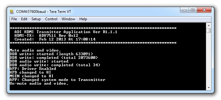
The reference design demonstrates:
Initializing the ADV7511 HDMI transmitter
Checking the current AVR operating mode
Setting the AV mute state
Displaying a test image on the HDMI monitor
Playing audio (if configured)
Changing Video Resolution
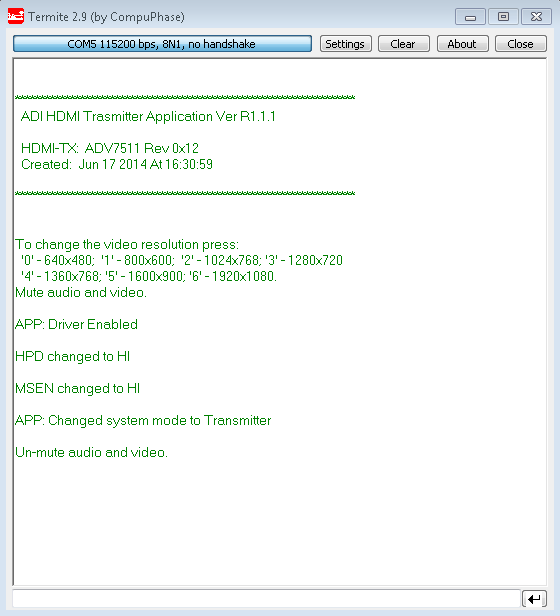
You can change the video resolution by typing a number from 0 to 6 in the terminal:
0: 640x480 @ 60Hz
1: 800x600 @ 60Hz
2: 1024x768 @ 60Hz
3: 1280x720 @ 60Hz
4: 1360x768 @ 60Hz
5: 1600x900 @ 60Hz
6: 1920x1080 @ 60Hz
Support
For additional support, please visit: