Production Testing
Overview
The purpose of this test procedure is to identify connectivity issues, poor soldering, and potential manufacturing defects in the AD-SYNCHRONA14-EBZ board. Some issues are directly identified by explicit part-targeted tests, while others are detected implicitly by running adjacent tests.
Test Duration
Step Description |
Estimated Time (minutes) |
|---|---|
Test bench setup |
10 min |
Software test |
15 min |
Total time |
25 min |
Test Requirements
Required Hardware
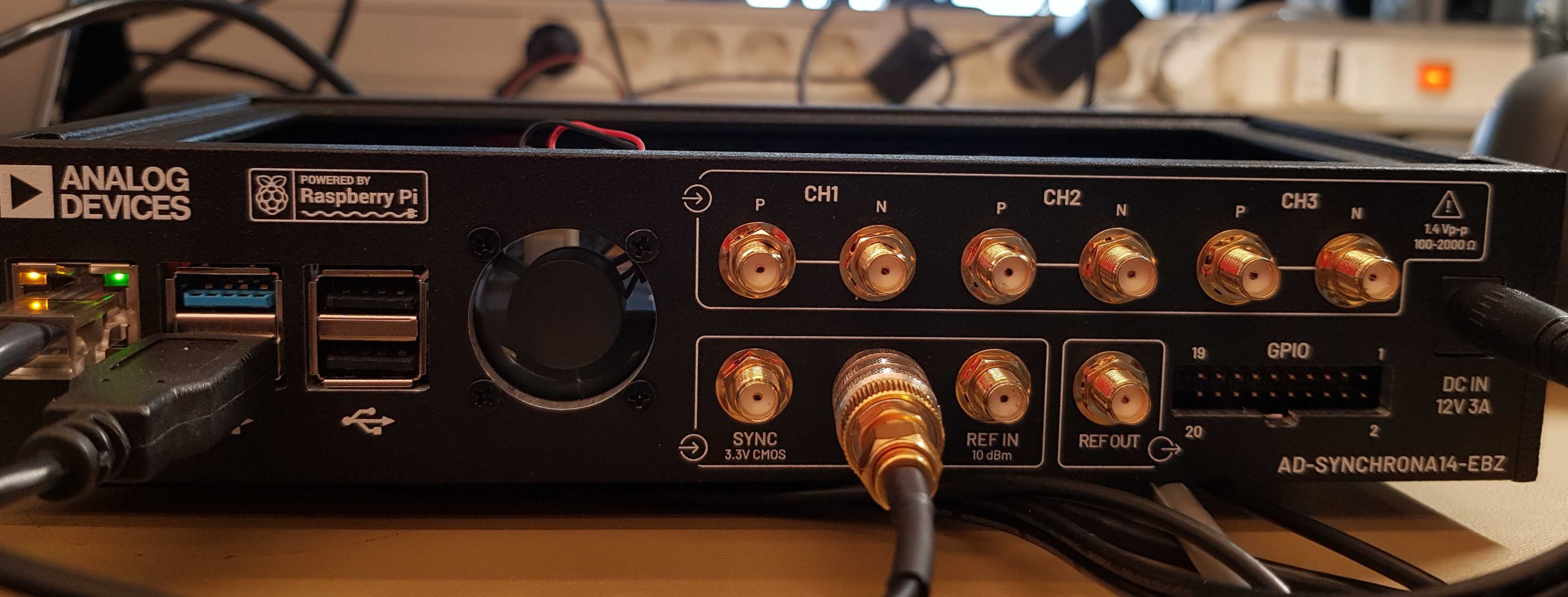
AD-SYNCHRONA14-EBZ board
Raspberry Pi 4, power cable (USB-C), HDMI cable
ADALM2000 with BNC adapter
BR-068851 connector board with ribbon cable
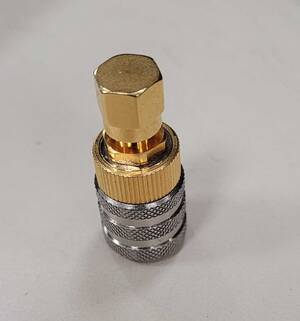
Twinax cable assembly
Micro-USB cable
Ethernet cable
QR code scanner
Mouse and keyboard
Dymo LabelWriter450 printer
Front panel SMA cable
Back panel SMA cable
50 Ohm terminator
Required Software
SD card with the test image
Required Setup

Insert the SD card into the Raspberry Pi.
Connect the ADALM2000’s BNC adapter to both the front and back panel SMA cables, with USB connection to the Synchrona board.
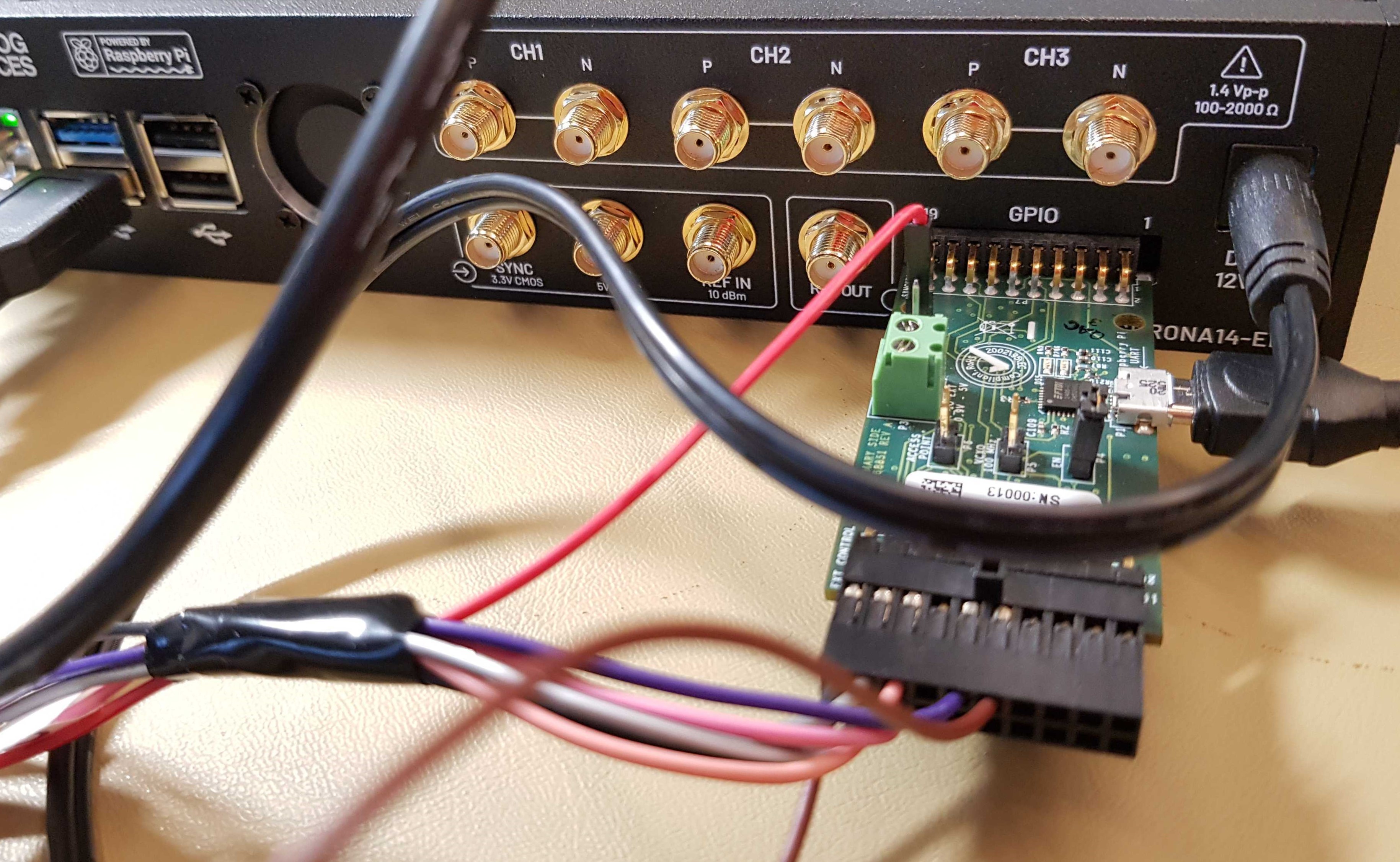
Connect the Raspberry Pi’s GPIO pins via ribbon cable to the BR-068851 adapter board, which connects via USB.
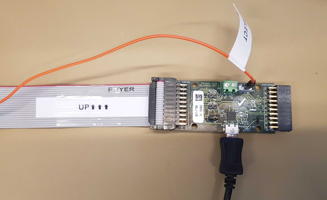
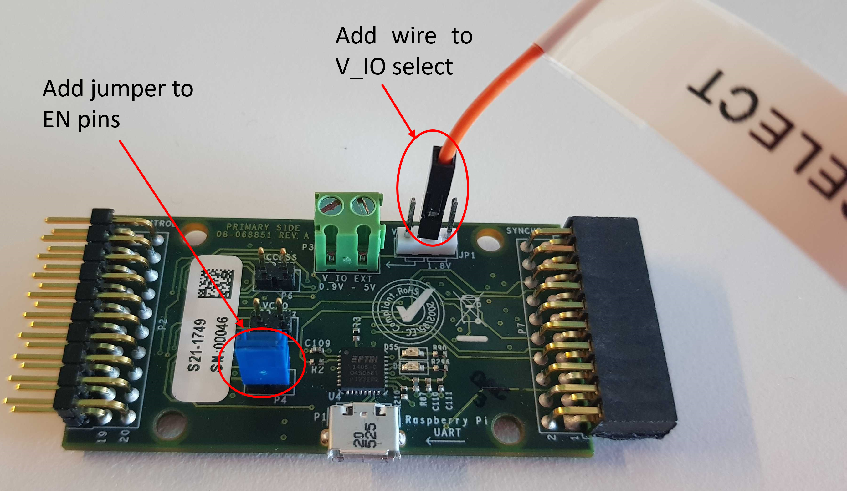
Add a wire to the V_IO select pin, and configure the EN pins with a jumper.
Connect an Ethernet cable between the Raspberry Pi and the Synchrona board.
Connect the QR code scanner, keyboard, and display to the Raspberry Pi.
Connect the Dymo LabelWriter450 printer via USB to the Raspberry Pi.
Power on the Raspberry Pi via USB-C.
Power on the Synchrona board by pressing the front panel power button. Allow approximately 30 seconds for initialization.
Test Process
Starting the Test


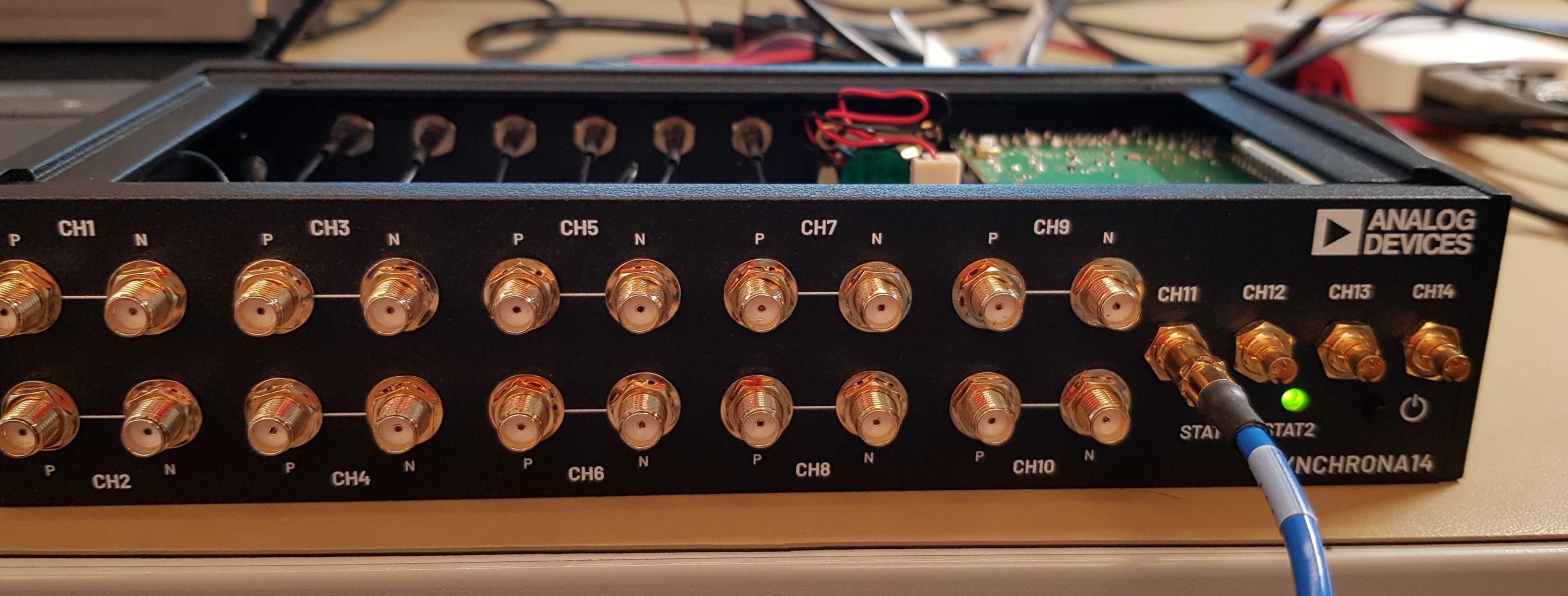
Front Panel Output Testing
Test channels 1-10 by sequentially connecting the front panel SMA cable to each port’s P and N connectors.


For channels 11-14, use the Twinax-to-SMA adapter with a probe connection.

Back Panel Input Testing
Communication Testing

Visual Inspection

Cleanup

Final Steps
The printer generates a label for placement on the board’s rear.

The test concludes with a PASSED or FAILED message displayed on screen.

If all tests pass, you can move onto the next D.U.T.
When you are done testing, press 2 and hit ENTER to power off the Raspberry Pi.