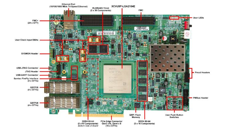
VCU118 Quick start
This guide provides instructions on how to setup the AD9208-DUAL-EBZ on the VCU118 (Virtex UltraScale+) platform.
All the products described on this page include ESD (electrostatic discharge) sensitive devices. Electrostatic charges as high as 4000V readily accumulate on the human body or test equipment and can discharge without detection. Although the boards feature ESD protection circuitry, permanent damage may occur on devices subjected to high-energy electrostatic discharges. Therefore, proper ESD precautions are recommended to avoid performance degradation or loss of functionality. This includes removing static charge on external equipment, cables, or antennas before connecting to the device.
The ADCs are set to run at full bandwidth mode 3 GSPS, which translates to a lane rate of 15.5 Gbps. Each converter has its own SYSREF that is driven from a common clock chip HMC7044. Ideally these SYSREF lines should be length matched; if not, the HMC has capability to adjust delays on its outputs. Sampling clocks are generated by the same HMC clock chip and should be ideally length matched as well.
Using Linux as software
Necessary files
Note
The SD card includes several folders in the root directory of the BOOT partition. In order to configure the SD card to work with a specific FPGA board and ADI hardware, several files must be copied onto the root directory. Using the host PC, drag and drop the required files onto the BOOT partition, and use the EJECT function when removing the SD card from the reader.
The following files are needed for the system to boot:
HDL bitstream:
system_top.bitLinux kernel image:
simpleImage.vcu118_dual_ad9208
Instructions on how to build the files from source can be found here:
AD9208-DUAL-EBZ HDL Project build documentation. More HDL build details at Build an HDL project.
Tip
Pre-built files for boards with 125 MHz VCXO can be downloaded from here.
Important
Some projects provide multiple devicetree files in the SD card’s boot folders. Make sure you select the devicetree that matches your specific use case.
Required Software
AMD Xilinx Vivado and Vitis (downloading Vitis from here will include Vivado as well)
A UART terminal (Putty/Tera Term/Minicom, etc.) with baud rate 115200 (8N1)
Required Hardware
AMD Xilinx VCU118 Rev 1.0 or later board
AD9208-DUAL-EBZ FMC board
2x Micro-USB cables
Ethernet cable
Signal generator
4-way splitter (optional)
Testing
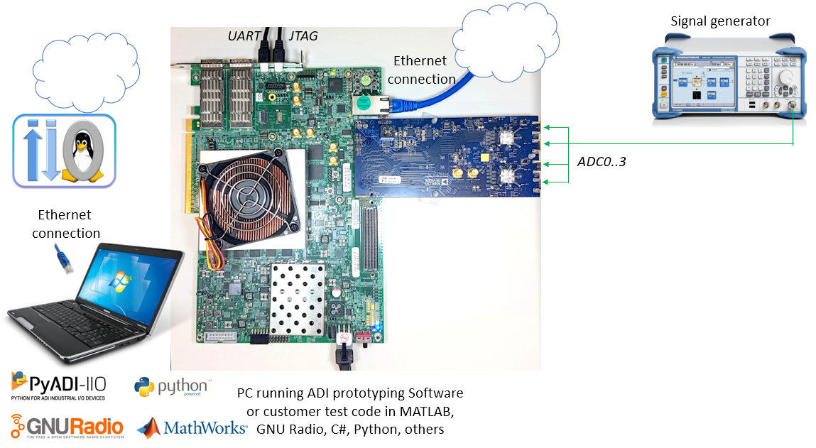
Creating the setup
Important
There are two options for powering the board, both require a rework:
In order to supply the board from the FMC connector, populate F1 with a 2A fuse. Use this method if you can ensure the FMC carrier can drive 2A on its 12V power line.
Use an external 12V power supply and connect it to the TP1 (PWR_IN) and TP2 (AGND) points.
Follow the steps in this order, to avoid damaging the components:
Connect the AD9208-DUAL-EBZ FMC board to the VCU118 FMC+ socket
Connect USB UART (Micro-USB) to your host PC
Connect USB JTAG (Micro-USB) to your host PC
Plug-in an Ethernet cable from your router/switch to the Ethernet port on the FPGA board
Connect the power supply for the FPGA
Turn on the power switch on the FPGA board
Program the board using
xsctor similar tool. See generic instructions for programming MicroBlaze-based systems at Build MicroBlaze Linux kernel.Observe console output messages on your terminal (use the first ttyUSB or COM port registered)
Boot messages
The following is what is printed in the serial console, after you have connected to the proper ttyUSB or COM port:
Ramdisk addr 0x00000000,
Compiled-in FDT at 8041955c
Linux version 4.14.0-g6f4b7f7 (gcc version 8.2.0 (crosstool-NG 1.20.0)) #4 Tue Aug 18 10:15:22 IST 2020
setup_cpuinfo: initialising
setup_cpuinfo: Using full CPU PVR support
wt_msr_noirq
setup_memory: max_mapnr: 0x30000
setup_memory: min_low_pfn: 0x80000
setup_memory: max_low_pfn: 0xb0000
setup_memory: max_pfn: 0xb0000
Zone ranges:
  DMA      [mem 0x0000000080000000-0x00000000afffffff]
  Normal   empty
Movable zone start for each node
Early memory node ranges
  node   0: [mem 0x0000000080000000-0x00000000ffffefff]
Initmem setup node 0 [mem 0x0000000080000000-0x00000000ffffefff]
On node 0 totalpages: 196608
free_area_init_node: node 0, pgdat 805c5a4c, node_mem_map 808e8000
  DMA zone: 1536 pages used for memmap
  DMA zone: 0 pages reserved
  DMA zone: 196608 pages, LIFO batch:31
pcpu-alloc: s0 r0 d32768 u32768 alloc=1*32768
pcpu-alloc: [0] 0
Built 1 zonelists, mobility grouping on.  Total pages: 195072
Kernel command line: console=ttyUL0,115200
PID hash table entries: 4096 (order: 2, 16384 bytes)
Dentry cache hash table entries: 131072 (order: 7, 524288 bytes)
Inode-cache hash table entries: 65536 (order: 6, 262144 bytes)
Memory: 769556K/786432K available (4197K kernel code, 145K rwdata, 1496K rodata, 3074K init, 96K bss, 16876K reserved, 0K cma-reserved)
Kernel virtual memory layout:
  * 0xffffe000..0xfffff000  : fixmap
  * 0xffffe000..0xffffe000  : early ioremap
  * 0xb0000000..0xffffe000  : vmalloc & ioremap
NR_IRQS: 64, nr_irqs: 64, preallocated irqs: 0
irq-xilinx: /amba_pl/interrupt-controller@41200000: num_irq=16, edge=0x35f8
/amba_pl/timer@41c00000: irq=1
clocksource: xilinx_clocksource: mask: 0xffffffff max_cycles: 0xffffffff, max_idle_ns: 19112604467 ns
xilinx_timer_shutdown
xilinx_timer_set_periodic
sched_clock: 32 bits at 100MHz, resolution 10ns, wraps every 21474836475ns
Calibrating delay loop... 49.35 BogoMIPS (lpj=246784)
pid_max: default: 32768 minimum: 301
Mount-cache hash table entries: 2048 (order: 1, 8192 bytes)
Mountpoint-cache hash table entries: 2048 (order: 1, 8192 bytes)
devtmpfs: initialized
random: get_random_u32 called from bucket_table_alloc+0x248/0x29c with crng_init=0
clocksource: jiffies: mask: 0xffffffff max_cycles: 0xffffffff, max_idle_ns: 19112604462750000 ns
futex hash table entries: 256 (order: -1, 3072 bytes)
NET: Registered protocol family 16
clocksource: Switched to clocksource xilinx_clocksource
NET: Registered protocol family 2
TCP established hash table entries: 8192 (order: 3, 32768 bytes)
TCP bind hash table entries: 8192 (order: 3, 32768 bytes)
TCP: Hash tables configured (established 8192 bind 8192)
UDP hash table entries: 512 (order: 1, 8192 bytes)
UDP-Lite hash table entries: 512 (order: 1, 8192 bytes)
NET: Registered protocol family 1
RPC: Registered named UNIX socket transport module.
RPC: Registered udp transport module.
RPC: Registered tcp transport module.
RPC: Registered tcp NFSv4.1 backchannel transport module.
random: fast init done
Skipping unavailable RESET gpio -2 (reset)
workingset: timestamp_bits=30 max_order=18 bucket_order=0
jffs2: version 2.2. (NAND) (SUMMARY)  (c) 2001-2006 Red Hat, Inc.
Block layer SCSI generic (bsg) driver version 0.4 loaded (major 252)
io scheduler noop registered
io scheduler deadline registered
io scheduler cfq registered (default)
io scheduler mq-deadline registered
io scheduler kyber registered
Serial: 8250/16550 driver, 4 ports, IRQ sharing disabled
40600000.serial: ttyUL0 at MMIO 0x40600000 (irq = 5, base_baud = 0) is a uartlite
console [ttyUL0] enabled
brd: module loaded
Xilinx SystemACE device driver, major=254
libphy: Fixed MDIO Bus: probed
xilinx_axienet 40c00000.ethernet: TX_CSUM 2
xilinx_axienet 40c00000.ethernet: RX_CSUM 2
libphy: Xilinx Axi Ethernet MDIO: probed
i2c /dev entries driver
i2c i2c-0: Added multiplexed i2c bus 1
at24 2-0050: 256 byte 24c02 EEPROM, writable, 1 bytes/write
i2c i2c-0: Added multiplexed i2c bus 2
i2c i2c-0: Added multiplexed i2c bus 3
i2c i2c-0: Added multiplexed i2c bus 4
i2c i2c-0: Added multiplexed i2c bus 5
i2c i2c-0: Added multiplexed i2c bus 6
i2c i2c-0: Added multiplexed i2c bus 7
i2c i2c-0: Added multiplexed i2c bus 8
pca954x 0-0075: registered 8 multiplexed busses for I2C switch pca9548
axi_adxcvr 44a60000.axi-adxcvr-rx: AXI-ADXCVR-RX (17.01.a) using GTY4 at 0x44A60000 mapped to 0xb0110000. Number of lanes: 8.
axi_adxcvr 44b60000.axi-adxcvr-rx: AXI-ADXCVR-RX (17.01.a) using GTY4 at 0x44B60000 mapped to 0xb0330000. Number of lanes: 8.
NET: Registered protocol family 17
ad9208 spi0.1: AD9208 PLL LOCKED
ad9208 spi0.1: Failed to request FastDetect IRQs (-6)
ad9208 spi0.1: AD9208 DUAL (MASTER with DMA) Rev. 3 Grade 0 (API 1.0.1) probed
ad9208 spi0.2: AD9208 PLL LOCKED
ad9208 spi0.2: Failed to request FastDetect IRQs (-6)
ad9208 spi0.2: AD9208 Rev. 3 Grade 0 (API 1.0.1) probed
iio_dmaengine_buffer_alloc:227 width 0 (DMA width >= 256-bits ?)
cf_axi_adc 44a10000.axi-ad9208-0-hpc: ADI AIM (10.01.b) at 0x44A10000 mapped to 0xb0101000, probed ADC AD9208 DUAL (MASTER with DMA) as MASTER
cf_axi_adc 44b10000.axi-ad9208-1-hpc: ADI AIM (10.01.b) at 0x44B10000 mapped to 0xb010b000, probed ADC AD9208 as MASTER
Freeing unused kernel memory: 3072K
This architecture does not have kernel memory protection.
Starting syslogd: OK
Starting klogd: OK
Initializing random number generator... done.
Starting network: udhcpc: started, v1.29.3
net eth0: Promiscuous mode disabled.
net eth0: Promiscuous mode disabled.
udhcpc: sending discover
xilinx_axienet 40c00000.ethernet eth0: Link is Down
udhcpc: sending discover
xilinx_axienet 40c00000.ethernet eth0: Link is Up - 1Gbps/Full - flow control rx/tx
udhcpc: sending discover
udhcpc: sending discover
udhcpc: sending select for 10.48.65.139
udhcpc: lease of <IP> obtained, lease time 21600
deleting routers
adding dns <IP>
adding dns <IP>
Starting dropbear sshd: OK
Starting IIO Server Daemon

Welcome to Buildroot
buildroot login: root
Password:
Useful commands for the serial terminal
The below commands are to be run in the serial terminal connected to the FPGA.
To find out the IP of the FPGA board, run the following command and take the IP specified at “eth0 inet”:
~$
ifconfig
To see the IIO devices detected, run:
~$
iio_info | grep iio:device
    iio:device0: hmc7044
    iio:device1: axi-ad9208-0-hpc (buffer capable)
    iio:device2: axi-ad9208-1-hpc
To verify the JESD204 link status, run:
~$
grep "" /sys/bus/platform/devices/*.axi-jesd*/status*
Both links should report Link status: DATA:
/sys/bus/platform/devices/44a90000.axi-jesd204-rx/status:Link is enabled
/sys/bus/platform/devices/44a90000.axi-jesd204-rx/status:Measured Link Clock: 350.821 MHz
/sys/bus/platform/devices/44a90000.axi-jesd204-rx/status:Reported Link Clock: 375.000 MHz
/sys/bus/platform/devices/44a90000.axi-jesd204-rx/status:Lane rate: 15000.000 MHz
/sys/bus/platform/devices/44a90000.axi-jesd204-rx/status:Lane rate / 40: 375.000 MHz
/sys/bus/platform/devices/44a90000.axi-jesd204-rx/status:LMFC rate: 46.875 MHz
/sys/bus/platform/devices/44a90000.axi-jesd204-rx/status:Link status: DATA
/sys/bus/platform/devices/44a90000.axi-jesd204-rx/status:SYSREF captured: Yes
/sys/bus/platform/devices/44a90000.axi-jesd204-rx/status:SYSREF alignment error: No
/sys/bus/platform/devices/44b90000.axi-jesd204-rx/status:Link is enabled
/sys/bus/platform/devices/44b90000.axi-jesd204-rx/status:Measured Link Clock: 350.821 MHz
/sys/bus/platform/devices/44b90000.axi-jesd204-rx/status:Reported Link Clock: 375.000 MHz
/sys/bus/platform/devices/44b90000.axi-jesd204-rx/status:Lane rate: 15000.000 MHz
/sys/bus/platform/devices/44b90000.axi-jesd204-rx/status:Lane rate / 40: 375.000 MHz
/sys/bus/platform/devices/44b90000.axi-jesd204-rx/status:LMFC rate: 46.875 MHz
/sys/bus/platform/devices/44b90000.axi-jesd204-rx/status:Link status: DATA
/sys/bus/platform/devices/44b90000.axi-jesd204-rx/status:SYSREF captured: Yes
/sys/bus/platform/devices/44b90000.axi-jesd204-rx/status:SYSREF alignment error: No
To verify lane information, run:
~$
jesd_status
To power off the system, run the following command, and wait for the final message to be printed, then power off the FPGA board from the switch as well.
~$
poweroff
To reboot the system, run:
~$
reboot
Important
Even though this is Linux, this is a persistent file system. Care should
be taken not to corrupt the file system – please shut down things, don’t
just turn off the power switch. Depending on your monitor, the standard
power off could be hiding. You can do this from the terminal as well with
sudo shutdown -h now or the above-mentioned command for powering
off.
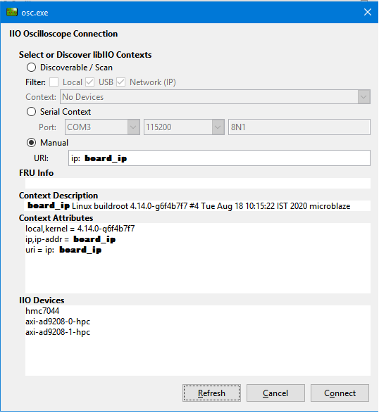
Capturing data with IIO Oscilloscope
From the UART console, find out the board IP address that was allocated by the DHCP server. If you do not use a DHCP server, manually assign an IP to the board Ethernet port. The default username:password for Linux is root:analog.
JESD SubClass 0 example
When the device is configured from device tree into subclass 0, we can observe the two links are not synchronized and the channels present phase differences.
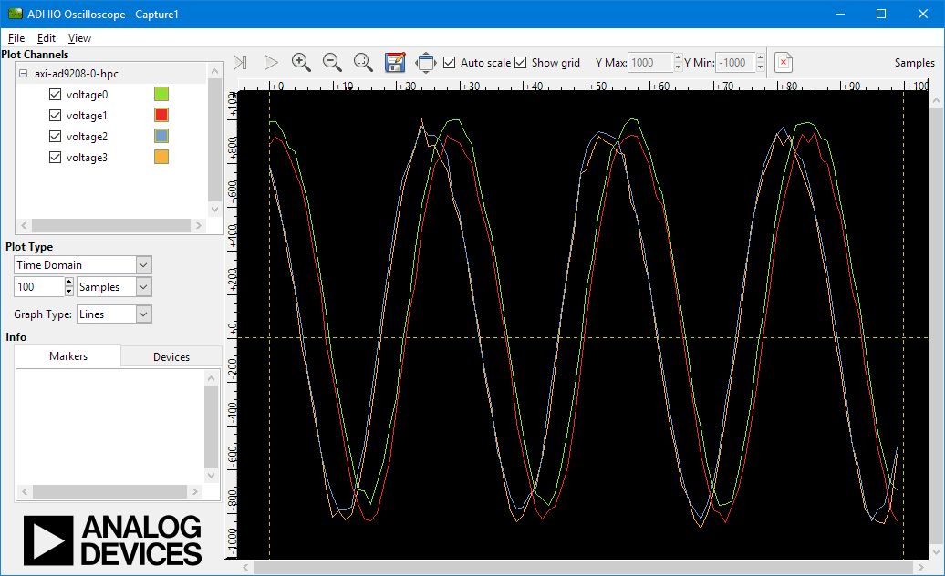
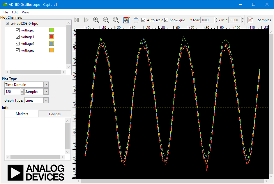
JESD SubClass 1 example
When the devices are configured into subclass 1 (default), we can observe the JESD links are synchronized and there is no phase difference between the input channels.
More information
Analog Devices will provide limited online support for anyone using the core with Analog Devices components (ADC, DAC, Video, Audio, etc) via the EngineerZone.