pyRadar - X-Band Radar Development Framework
Comprehensive guide for setting up and using pyRadar, a Python-based radar development framework for the X-Band Development Kit.
Overview
pyRadar is a modular Python framework designed to simplify radar application development on the X-Band Development Kit. It provides high-level APIs for hardware control, signal processing, and real-time visualization, enabling rapid prototyping of FMCW radar algorithms.
Key Capabilities
Hardware Control
AD9081 MxFE Configuration - Full TX/RX control with NCO, buffer, and channel configuration
ADAR1000 Phased Array - Custom driver for 32-element beamforming control
XUD1A Converter - X/C-band up/down converter configuration with LO control
Synchronization - Precise TDD timing for FMCW radar operation
Signal Processing
FMCW Processing - Beat frequency extraction and range calculation
Clutter Subtraction - Baseline mesh capture for static clutter removal
Analog Beamforming - Phase-calibration-based beam steering
Radar Pilots
FMCW Range - Single-beam range profile with live PyQtGraph display
FMCW Scan - Electronically steered azimuth sweep with range-angle heatmap
Important
pyRadar requires proper hardware setup and calibration before running radar pilots. Follow the complete setup procedure to ensure system functionality.
Installation and Setup
Follow these steps to configure your PC and hardware for pyRadar operation.
Prerequisites
Hardware Requirements:
X-Band Development Kit with ZCU102, AD9081, XUD1A, and ADAR1000 boards
16 GB SD card for Kuiper Linux
USB to UART cable (included with ZCU102)
Ethernet connection (direct or USB-to-Ethernet adapter)
12V DC power supplies
Software Requirements:
Windows PC (Windows 10 or later recommended)
Python 3.10.0
PuTTY or similar terminal emulator
Balena Etcher or similar SD card imaging tool
Internet connection for package downloads
Step 1: Prepare SD Card with Kuiper Linux
Prepare your SD card with the Kuiper Linux operating system:
See: SD Card Configuration Guide for complete instructions on:
Downloading ADI Kuiper Linux
Formatting the SD card
Flashing the image using Balena Etcher
Verifying the installation
Note
Kuiper Linux includes pre-installed ADI tools and drivers required for the X-Band platform.
Step 2: Install CP210x USB-UART Driver
Install the USB to UART bridge driver for serial communication:
Download the driver for your operating system:
Windows: CP210x Universal Windows Driver
Select appropriate version (x64 recommended)
Run the installer with administrator privileges
Follow the installation wizard
Restart your computer if prompted
Verify Installation:
Open Device Manager (Win + X → Device Manager)
Connect ZCU102 USB cable
Check “Ports (COM & LPT)” for “Silicon Labs CP210x USB to UART Bridge”
Note the COM port number (e.g., COM3)
Step 3: Install PuTTY
Install PuTTY for serial terminal access:
Visit PuTTY Download Page
Download the appropriate installer:
Windows: 64-bit MSI installer recommended
Run the installer and follow the installation wizard
Launch PuTTY to verify successful installation
PuTTY Configuration for ZCU102:
Connection type: Serial
Serial line: COM[X] (use COM port from Device Manager)
Speed: 115200
Data bits: 8
Stop bits: 1
Parity: None
Flow control: None
Step 4: Install Python 3.10.0
Set up the Python development environment:
Download the Windows installer (64-bit)
Run the installer:
✅ Check “Add Python 3.10 to PATH”
Click “Install Now”
Verify installation:
python --version
Expected output:
Python 3.10.0
Important
Python 3.10.0 is required for compatibility with Genalyzer and other dependencies. Do not use Python 3.11+ as some packages may not be compatible.
Step 5: Install Python IDE
Install your preferred Python development environment:
Option A: Visual Studio Code (Recommended)
Download from VS Code Website
Install the Python extension
Configure Python interpreter to 3.10.0
Option B: PyCharm Community
Download from JetBrains Website
Install and configure Python 3.10.0 interpreter
Option C: Spyder
Install via pip:
pip install spyder
Launch with
spydercommand
Step 6: Clone pyRadar Repository
Obtain the pyRadar source code:
Option A: Git Clone ( NOT available at this time)
git clone <repository_url>
cd pyRadar
Option B: Download ZIP
Download the pyRadar repository as ZIP or your FAE will share this with you
Extract to your desired location
Navigate to the extracted folder
Step 7: Create a Python Virtual Environment to run the code from
To ensure we are running from a verified software build/package installation, we will create a virtual environment using the following steps
Open a terminal in the pyRadar directory using your chosen IDE, e.g.
cd "C:\Users\svc_adefsysplat\Desktop\System_Platform_Team\x-band\pyRadar"
Create the virtual environment:
python -m venv xbdp_python_venv
Activate the virtual environment:
.\\xbdp_python_venv\\Scripts\\activate
Upgrade the Python pip version to ensure you are running the latest:
python -m pip install --upgrade pip
Install all required Python packages NOTE: You will need an active internet connection to complete this step
pip install -r requirements.txt
This completes the pre-configuration for the software environment
Step 8: Configure Hardware Connection
Connect to the X-Band Development Kit:
Physical Setup:
Insert flashed SD card into ZCU102 (slot J1001)
Connect USB cable from ZCU102 to PC (for UART)
Connect Ethernet cable:
Direct connection: ZCU102 to PC Ethernet port
Network connection: ZCU102 to network switch/router
USB-Ethernet adapter: Configure adapter IP if needed
Connect 12V power supplies to all boards
Power on the system
Serial Connection:
Open PuTTY with COM port settings (115200, 8N1)
Power on ZCU102
Watch boot sequence in PuTTY
Login if prompted:
Username:
rootPassword:
analog
Note
Once logged in, run iio_attr -c on the ZCU102 to list all detected IIO devices. You should see 40 devices in total. A count lower than 40 indicates a hardware detection issue that should be resolved before proceeding.
Network Configuration:
Check ZCU102 eth0 interface IP address:
ifconfig eth0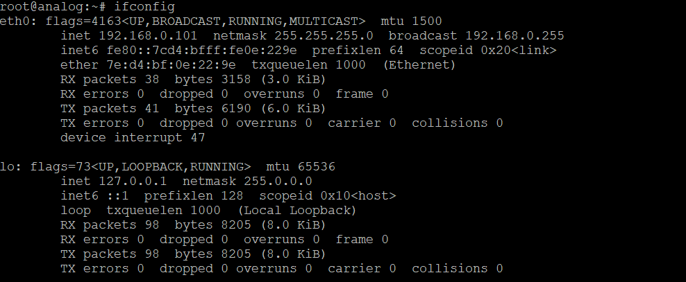
Note the IP address (e.g.,
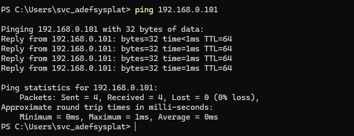
192.168.0.101)Verify connectivity from PC:
ping 192.168.0.101
Tip
For USB-Ethernet adapters, you may need to configure the adapter’s IP address to be on the same subnet as the ZCU102 (e.g., PC: 192.168.0.10, ZCU102: 192.168.0.101).
Step 9: Configure pyRadar
Update pyRadar configuration for your system:
In
\x-band\pyRadardirectory, openmain.pyin your Python IDELocate the IP address configuration section:
uri = "ip:192.168.0.101"
Update the IP address to match your ZCU102 from the earlier section (192.168.0.101)
Save the file
Verify ADI Device Detection:
On the ZCU102, check that devices are detected:
root@analog:~# iio_info -n <zcu102_ip>
You should see AD9081, ADAR1000, and other IIO devices listed.
Step 10: Run Your First Pilot - FMCW Examples
Test the installation with a simple pilot:
In
\x-band\pyRadardirectory, openmain.pyin your IDE.Set the point source frequency at the top of
main.py:source_freq_ghz = 10.0694 # Point Source Frequency for calibration in GHz
Run the script:
python .\main.py
Calibration Menu — the first menu prompts you to select a calibration mode:
=== XBDP Calibration Menu ===
1. Rx Calibration
2. Full (Rx & Tx) Calibration
3. Load saved calibration
4. Load default calibration
q. Quit
Option 1 — RX Calibration: Place a point source approximately 1.5 m from the front of the Stingray antenna. The ADC data is captured and plotted for review. Press Close to continue, then remove the RF source when prompted.
Option 2 — Full Calibration: Runs RX calibration first, then prompts you to connect an antenna to J9 on Stingray for TX calibration.
Option 3 — Load saved calibration: Loads the most recent calibration JSON from the
cal files/directory.Option 4 — Load default calibration: Skips calibration and applies factory defaults (gain=127, phase=0 for all elements).
Important
Calibration results are saved automatically to
cal files/as a timestamped JSON file. Stale calibration files older than 30 days are purged on startup.After calibration, the hardware connects automatically and the Pilot Demo Menu appears:
=== XBDP Pilot Demo Menu ===
1. Run the FMCW Range Pilot
2. Run the FMCW Scan Pilot
q. Quit
FMCW Range Pilot (Option 1):
A live PyQtGraph window opens showing the range profile.
Move a reflector in front of the antenna — watch the detected range update in real time.
Range resolution is approximately 0.6 m.
To exit, close the window; the script completes cleanly.
FMCW Scan Pilot (Option 2):
You will be asked:
Enable clutter mesh? (Y/n)— EnterYto capture a static baseline before scanning (recommended for target isolation).A live heatmap opens with angle on the X-axis (degrees) and range on the Y-axis (metres).
Move a reflector in front of the antenna — a bright hot spot appears at the target’s range and angle.
To exit, press the
Qkey; the window closes and the script completes.
Sample Data and Results
RX Calibration Example
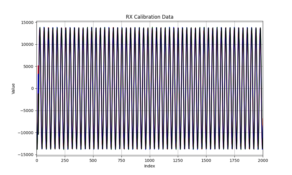
Four-channel calibration showing phase and gain matching across all ADC channels. The plot demonstrates successful alignment of all array elements to a common reference.
Calibration Metrics:
Phase error: < 5° RMS across all channels
Amplitude error: < 0.5 dB across all channels
Reference element: Channel 0
FMCW Range Example
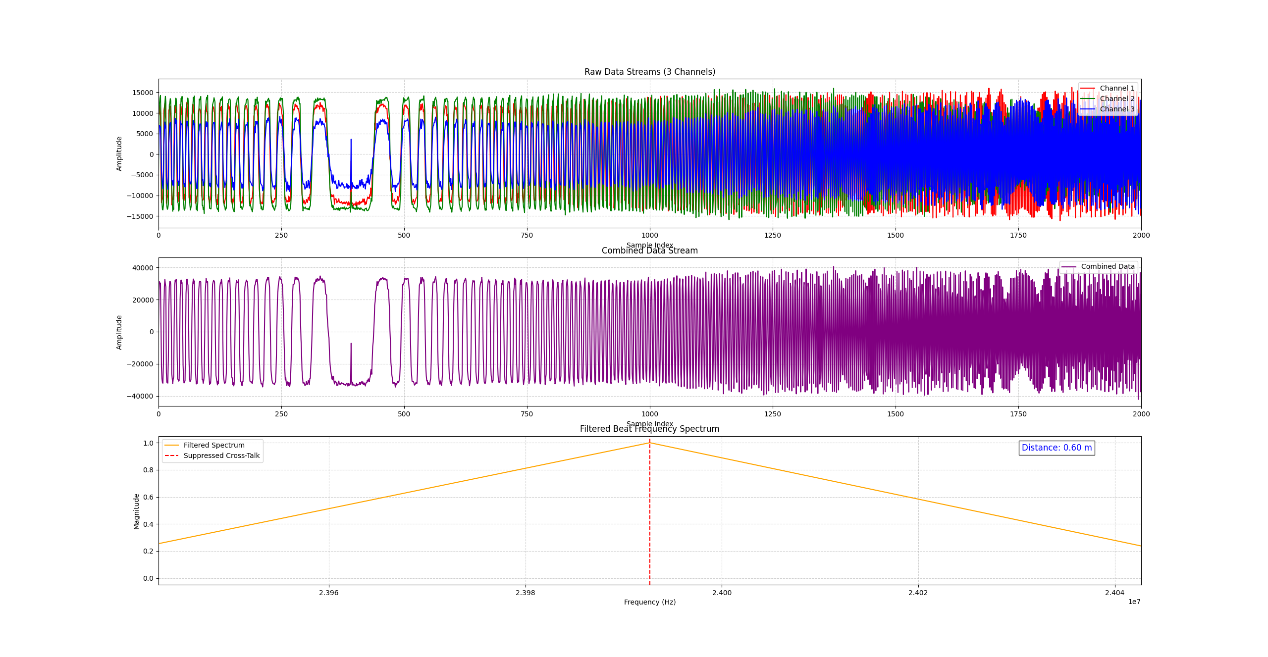
FMCW range showing the captured ADCs on the top graph of the transmitted FMCW signal and the returned beat frequency on the lower graph and resulting Range on the top right of this lower graph.
Range Parameters:
Range resolution: ~0.6m
FMCW Scan Example
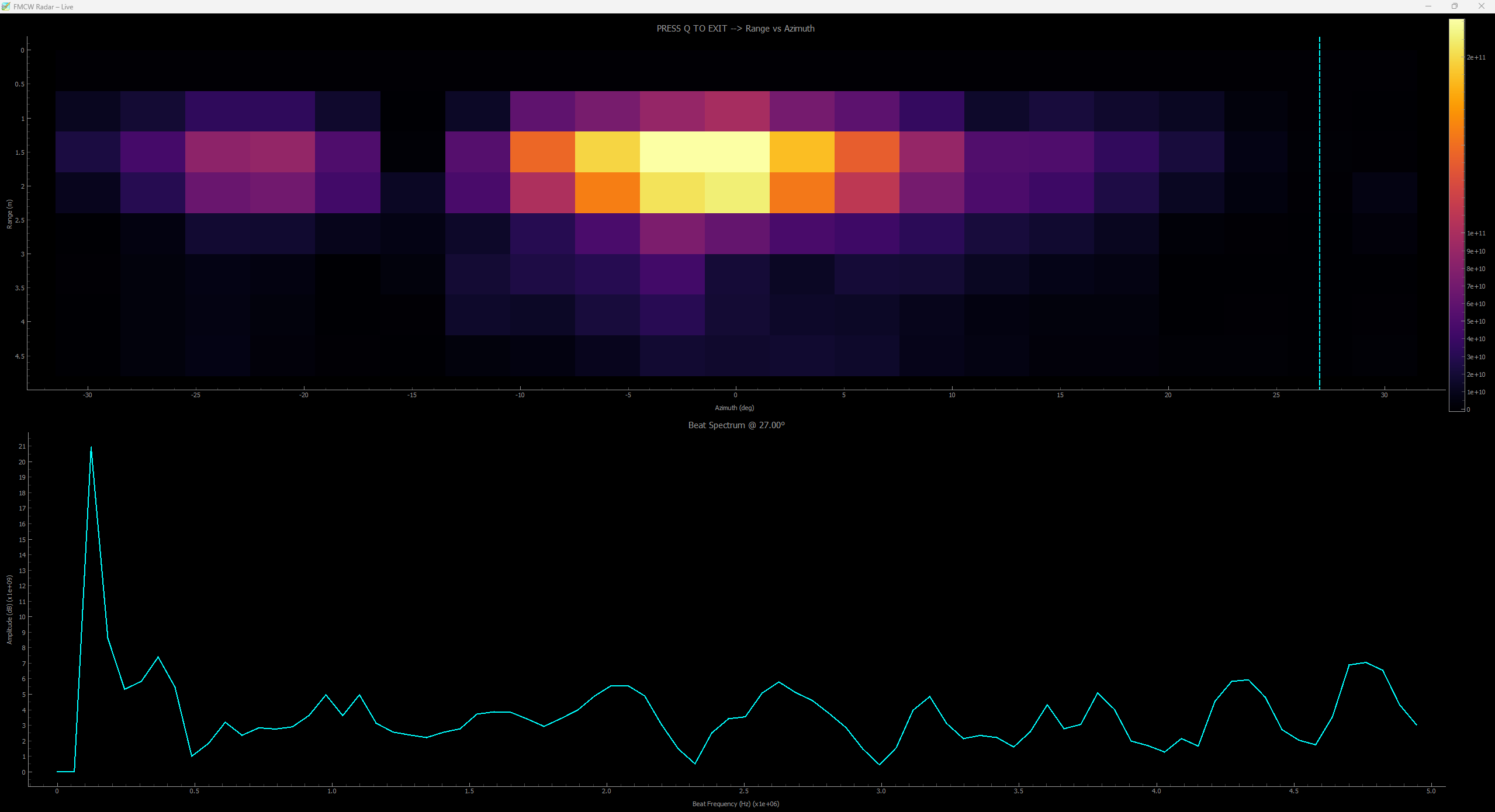
FMCW horizon scan showing range-angle heatmap data. The visualization demonstrates the system’s ability to detect and locate targets across azimuth angles with range resolution.
Scan Parameters:
Azimuth range: -60° to +60°
Range resolution: ~0.6m
Color scale: Normalized dB
Tip
Use sample data to verify your installation and compare results. Similar patterns indicate proper system configuration.
System Architecture
The pyRadar framework is organized as follows:
pyRadar/
├── main.py                         # Entry point: menus, config, hardware init
├── requirements.txt                # Python package dependencies
├── cal files/                      # Saved calibration JSON files (auto-created)
├── custom_libs/                    # Custom hardware drivers
│   ├── __init__.py
│   └── adar1000.py                 # Modified ADAR1000 driver for X-Band
├── pilot_functions/                # Radar demonstration pilots
│   ├── __init__.py
│   ├── fmcw_range.py               # FMCW single-beam range pilot
│   └── fmcw_scan.py                # FMCW azimuth scan pilot
├── radar_utils/                    # Core library modules
│   ├── __init__.py
│   ├── hardware_setup.py           # AD9081, XUD1A, and ADAR1000 initialisation
│   ├── calibration.py              # Per-element RX/TX calibration routines
│   ├── cal_manager.py              # Calibration file save/load/purge
│   ├── tx_rx_cal.py                # Full RX and TX calibration sequences
│   ├── signal_processing.py        # DSP functions (FFT, heatmap, beat calc)
│   ├── sync_config.py              # TDD timing and FMCW waveform generation
│   ├── radar_plotting.py           # PyQtGraph real-time visualisation
│   ├── rx_1tone.json               # Single-tone RX calibration config
│   ├── rx_2tone.json               # Dual-tone RX calibration config
│   └── utils.py                    # Miscellaneous helpers
└── tools/                          # Offline post-processing utilities
    ├── check_h5.py                  # Inspect HDF5 capture files
    └── post_process_h5.py           # Post-process captured HDF5 data
Module Descriptions
main.py
Entry point for the entire pyRadar application.
Configuration (edit these at the top of the file):
uri— ZCU102 IP address (defaultip:192.168.0.101)BW— chirp bandwidth in Hz (default 250 MHz)num_chirps— chirps per ADC buffer (default 512)source_freq_ghz— point-source frequency for calibration (GHz)subarray_modes— per-subarray role:{1:"rx", 2:"rx", 3:"tx", 4:"rx"}
Shared state dictionaries:
cal— calibration results:cal_ant_fix,loFreq,rx_phase_cal,tx_phase_cal, per-element gain/attenuation dictshw— hardware handles:conv(AD9081),sray(ADAR1000),tddn(TDD engine),PRF,subarray
Menus (executed in order on startup):
calibration_menu()— prompts for calibration mode, then stores results incalconnect_and_configure_xbdp()— connects to hardware and applies loaded calibrationpilot_menu_loop()— prompts for pilot selection in a loop
pilot_functions/fmcw_range.py
FMCW Range Pilot — single-beam live range profile.
FMCWRange(conv, tddn, cal_ant_fix, subarray_modes, iq, BW, PRF, duty_cycle)
Continuously captures IQ data and dechirps against the transmitted chirp reference.
Applies a low-pass filter to reject the sum-frequency product, then FFTs the beat signal.
Converts the beat frequency to range:
R = c · T · f_beat / (2 · BW)Displays a live PyQtGraph range profile; close the window to exit.
Printed on launch:
TX/RX subarray assignments, enabled ADC channels
Chirp duration, slope, range resolution, maximum unambiguous range
pilot_functions/fmcw_scan.py
FMCW Scan Pilot — electronically steered azimuth sweep with heatmap display.
FMCWScan(conv, sray, cal_ant_fix, subarray_modes, iq, BW, PRF,
         scan_min, scan_max, scan_step, analog_phase_cal, tx_phase_cal,
         cluttermesh=True)
Sweeps beam from
scan_mintoscan_maxdegrees inscan_stepincrements.At each angle, programs new phase values into the ADAR1000 array, captures one ADC frame, dechirps, and FFTs to produce a range column.
Assembles all columns into a 2-D range×angle heatmap.
Optional
cluttermesh: captures a multi-frame static baseline before the live scan and subtracts it to remove fixed clutter.Press
Qto exit. Default scan limits: −25° to +25° in 5° steps.
radar_utils/hardware_setup.py
Hardware initialisation for AD9081, XUD1A, and ADAR1000.
Key functions:
setup_ad9081(url, rx_buffer_size, tx_cyclic_buffer, rx_cyclic_buffer,
             tx_ddr_offload, rx_channel_nco_frequencies,
             tx_channel_nco_frequencies, rx_main_nco_frequencies,
             tx_main_nco_frequencies, rx_enabled_channels)
Configures the AD9081 MxFE:
RX main NCO defaults to 500 MHz; TX main NCO defaults to 4.5 GHz.
Channel NCOs default to 0 Hz (DC).
rx_enabled_channelscontrols which ADC channels are active (derived fromsubarray_modes).Returns a configured
adi.ad9081object.
setup_xud1a(conv, channel_modes, lo_freq)
Configures the XUD1A up/down converter:
Sets each subarray channel to RX or TX mode.
Programs the LO frequency (populated from calibration).
setup_stingray(uri, subarray_modes)
Initialises the 8-chip, 32-element ADAR1000 array:
Maps chip IDs, device layout, and element numbering.
Returns
(sray, subarray)— the array object and a per-subarray element mapping.
build_rx_channel_config(subarray_modes)
Derives which ADC channels to enable and the subarray-to-data-index mapping used by all signal-processing functions.
radar_utils/calibration.py
Per-element RX and TX calibration building blocks.
Channel control:
Function |
Purpose |
|---|---|
|
Enables listed element channels (1–32) for RX or TX |
|
Disables listed element channels |
Data capture:
Function |
Purpose |
|---|---|
|
Raw ADC capture — returns 4-channel IQ array |
|
Capture with antenna path-length correction applied |
|
Capture for mid-calibration test steps |
Calibration routines:
Function |
Purpose |
|---|---|
|
Measures per-element RX gain and fits correction codes |
|
Null-steering phase calibration (analog domain) |
|
NCO-based digital phase trim |
|
Finds phase delay using a fixed reference element |
radar_utils/cal_manager.py
Manages saving, loading, and housekeeping of calibration files.
Key functions:
Function |
Purpose |
|---|---|
|
Saves all calibration data to a timestamped JSON in |
|
Loads the most recent JSON from |
|
Unpacks a loaded cal dict into the |
|
Deletes cal files older than |
Calibration JSON files contain: loFreq, cal_ant_fix, per-element rx_phase_cal, tx_phase_cal, rx_gain_dict, rx_atten_dict, tx_gain_dict, tx_atten_dict, and per-element hardware register snapshots.
radar_utils/tx_rx_cal.py
Full-system RX and TX calibration sequences.
Key functions:
setup(N_rx)
Defines the physical subarray-to-element mapping, ADC channel map, and reference elements. Returns all parameters needed to run calibration.
device_init(N_rx, url, default=True)
Connects to the ZCU102, constructs the adar1000_array object with the correct chip IDs and element map, and sets default NCO frequencies.
rx_cal_full(url, sray, conv, subarray, subarray_ref, subarray_targ,
            adc_map, adc_ref, source_freq_ghz, subarray_modes)
Full RX calibration sequence:
Gain equalisation — measures per-element power and programmes correction codes.
Analog phase calibration — null-steering sweep per element.
Digital phase trim — NCO residual removal. Returns
(cal_ant_fix, loFreq, rx_phase_cal, rx_gain_dict, rx_atten_dict).
tx_cal_full(url, sray, conv, subarray, source_freq_ghz, subarray_modes)
Full TX calibration sequence using the maximum-power method — sweeps each TX element phase while measuring combined output power. Returns (tx_phase_cal, tx_gain_dict, tx_atten_dict).
radar_utils/signal_processing.py
DSP building blocks used by both pilots.
Function |
Purpose |
|---|---|
|
Extracts beat frequency and estimates range from an FMCW capture |
|
Builds one azimuth column of the range-angle heatmap |
|
Circularly shifts FFT to zero out the internal cross-talk leakage peak |
|
Normalises a heatmap to a dB scale with configurable floor and ceiling |
|
Pre-computes Hanning window, coherent gain, and frequency axis for length-N FFT |
|
2-D range×Doppler FFT with optional MTI filter |
|
Batch version of |
|
Compensates R⁴ path loss on a range-Doppler map |
|
2-D CA-CFAR detector |
|
Computes key range-Doppler axis parameters |
radar_utils/sync_config.py
TDD timing engine and FMCW waveform generation.
sys_sync(conv, tddn, PRF, num_chirps, BW, duty_cycle, mode, subarray_modes)
Configures the TDD controller and uploads the TX chirp waveform:
FMCW mode: sets
rx_buffer_size = samples_per_chirp × num_chirps, programs all TDD channels, generates and tiles the linear-chirp waveform, uploads to the AD9081 DAC cyclic buffer.Returns the ideal IQ chirp array
iqused later for dechirping.
sync_disable(conv, tddn, sray, subarray)
Shuts down TDD, disables the DAC cyclic buffer, and disables all Stingray channels cleanly on exit.
radar_utils/radar_plotting.py
PyQtGraph-based real-time visualisation (replaces matplotlib for live updates).
Function |
Purpose |
|---|---|
|
Creates PyQtGraph window for the FMCW Range pilot (raw ADC + beat spectrum + range readout) |
|
Updates all plots in the range GUI each capture loop |
|
Creates the range-angle heatmap window for the FMCW Scan pilot |
|
Updates the heatmap and angle/range cursors each scan sweep |
|
Initialises a range-Doppler map display window |
|
Creates a |
Custom Libraries
custom_libs/adar1000.py — Modified ADAR1000 Phased Array Beamformer Driver
This custom driver preserves calibrated gain and phase weights when steering the beam. The standard pyadi-iio driver overwrites these values on every beam update; this version maintains the per-element calibration offsets.
Tip
The custom ADAR1000 driver is required for proper phased-array beamforming on the X-Band platform. Do not replace it with the standard pyadi-iio version.
Additional Resources
Documentation
pyadi-iio Documentation - Python IIO library reference
AD9081 Product Page - MxFE datasheet and resources
ADAR1000 Product Page - Beamformer documentation
Kuiper Linux Documentation - Linux image documentation
Tools and Software
IIO Oscilloscope - Real-time IIO device visualization
Genalyzer - Signal analysis library
Contact and Support
pyRadar Author: Brandon Lopez - brandon.lopez@analog.com
ADI Support: EngineerZone Community
GitHub Issues: Report bugs and request features in repository
Pilot Deep-Dives
Detailed technical breakdowns of individual radar pilots, covering their signal-processing mechanics and tunable parameters:
See also
Hardware Assembly Guide - X-Band platform assembly instructions
EEPROM Programming - FMC EEPROM setup for VADJ
SD Card Configuration - Kuiper Linux SD card preparation
ZCU102 Configuration - ZCU102 boot and network setup