SD Card Configuration
This guide covers the complete process for preparing, formatting, flashing, and configuring an SD card for the X-Band Phased Array Development Platform.
Prerequisites
Before starting, ensure you have:
SD Card: Minimum 16GB recommended (32GB preferred)
SD Card Formatter: Download from SD Association
BalenaEtcher: Download from balena.io
ADI Kuiper Linux Image
SD Card Reader: USB or built-in card reader
Host Computer: Windows, Mac, or Linux
Important
This version of Kuiper Linux is not yet released publicly. Reach out to an ADI FAE for a copy
Step 1: Format the SD Card
Before programming the SD Card, it must be properly formatted and erased.
Insert the SD Card into your card reader
Open SD Card Formatter software
Select your SD Card from the drive dropdown
Verify you’ve selected the correct drive
Choose Quick Format option
Label the SD Card (optional, e.g.,
XBand_2024)Click Format and confirm
Wait for completion - you should see a success prompt
Close SD Card Formatter
Warning
Double-check that you’ve selected the correct drive. Formatting will erase all data on the selected drive.
Note
Use the SD Card Formatter program rather than Windows/Mac built-in formatting tools to ensure proper SD card structure.
Step 2: Flash the Kuiper Linux Image
Open BalenaEtcher application
Click “Flash from file”
Select the Kuiper Linux image:
Navigate to your downloaded
.imgfileExample:
2024-06-18-ADI-Kuiper-full.img
Click “Select target”
Select your SD Card:
CRITICAL: Double-check you’ve selected the correct drive
Selecting the wrong drive will erase its contents
Click “Flash!”
This may require administrator privileges
The flashing process takes approximately 10-15 minutes
A verification process will follow the flashing
Important
The verification will always fail at the end - this is expected and can be ignored. Simply close BalenaEtcher when the flashing completes.
Flashing Progress
During the flashing process, BalenaEtcher will show:
Flashing: Writing the image to the SD card (~10 minutes)
Validating: Verifying the written data (~5 minutes)
Fail message: Expected - ignore and close the application
Step 3: Prevent SD Card Encryption (For automatic PC encryptions)
Important
ADI Internal Users Only: Within ADI networks, if files are moved directly in Windows Explorer, the SD Card will get encrypted and fail to boot. Follow these steps to work around this issue.
Map Network Drive to Avoid Encryption
After flashing is complete, you must move specific files to the SD Card. To avoid encryption:
Remove and re-insert the SD Card into your PC
Windows will mount it as two drives: BOOT and rootfs
Open Windows Explorer (but don’t navigate to the SD Card yet)
Right-click the BOOT drive and select Properties
Go to the Sharing tab
Copy the network drive path (e.g.,
\\COMPUTERNAME\BOOT)Right-click “This PC” and select Map Network Drive
Paste the network path you copied
Click Finish
Use this mapped network drive for all file operations
Files copied through the network drive will not be encrypted
Tip
External Users: You can skip the network drive mapping and copy files directly to the BOOT partition.
Step 4: Copy Required Files
The SD card needs specific boot files copied to the root directory of the BOOT partition.
File Locations
You need to copy three files from your HDL build or reference design:
Image: Linux kernel image
Source:
zynqmp-common/Image
BOOT.BIN: First-stage bootloader and FPGA bitstream
Source:
zynqmp-zcu102-rev10-stingray/BOOT.BIN
system.dtb: Device tree blob
Source:
zynqmp-zcu102-rev10-stingray/<clock_config>/system.dtb
Note
The system.dtb file location depends on your clocking configuration. Common options:
vcxo100/system.dtb- 100 MHz VCXO referencexo122p88/system.dtb- 122.88 MHz XO reference Select the system.dtb that matches your hardware clocking setup.
Copy Procedure
Navigate to the BOOT drive (or mapped network drive for ADI users)
Copy Image file:
From:
<build_directory>/zynqmp-common/ImageTo: Root of BOOT drive
Copy BOOT.BIN:
From:
<build_directory>/zynqmp-zcu102-rev10-stingray/BOOT.BINTo: Root of BOOT drive
Overwrite if it already exists
Copy system.dtb:
From:
<build_directory>/zynqmp-zcu102-rev10-stingray/<clock_config>/system.dtbTo: Root of BOOT drive
Overwrite if it already exists
Warning
Ensure you copy the correct system.dtb for your clocking configuration. Using the wrong device tree will cause boot failures or hardware misconfiguration.
File Verification
After copying, the root of your BOOT partition should contain:
BOOT/
├── Image
├── BOOT.BIN
└── system.dtb
Step 5: Safely Remove SD Card
Close Windows Explorer and any programs accessing the SD card
Unmount/Eject the SD Card:
Right-click the drive and select “Eject”
Or use the “Safely Remove Hardware” icon in the system tray
Wait for confirmation that it’s safe to remove
Remove the SD Card from your card reader
Step 6: Install and Boot
Installation
Power down the X-Band platform completely
Remove any existing SD Card from the ZCU102
Insert the newly programmed SD Card into the ZCU102 SD card slot
Ensure ZCU102 is configured for SD boot (see ZCU102 Configuration)
First Boot
Open a serial terminal on your host PC:
Baud rate: 115200
Data bits: 8
Parity: None
Stop bits: 1
Flow control: None
Connect USB-UART cable from PC to ZCU102 (J83)
Power on the X-Band platform (see power-on sequence in main Setup guide)
Monitor boot process in the serial terminal:
U-Boot messages appear (~5 seconds)
Linux kernel boot messages (~15 seconds)
System initialization (~20 seconds)
Login prompt appears (~30-40 seconds total)
Verify Boot Success
Login with credentials:
Username:
rootPassword:
analog
Wait 60 seconds for system initialization to complete
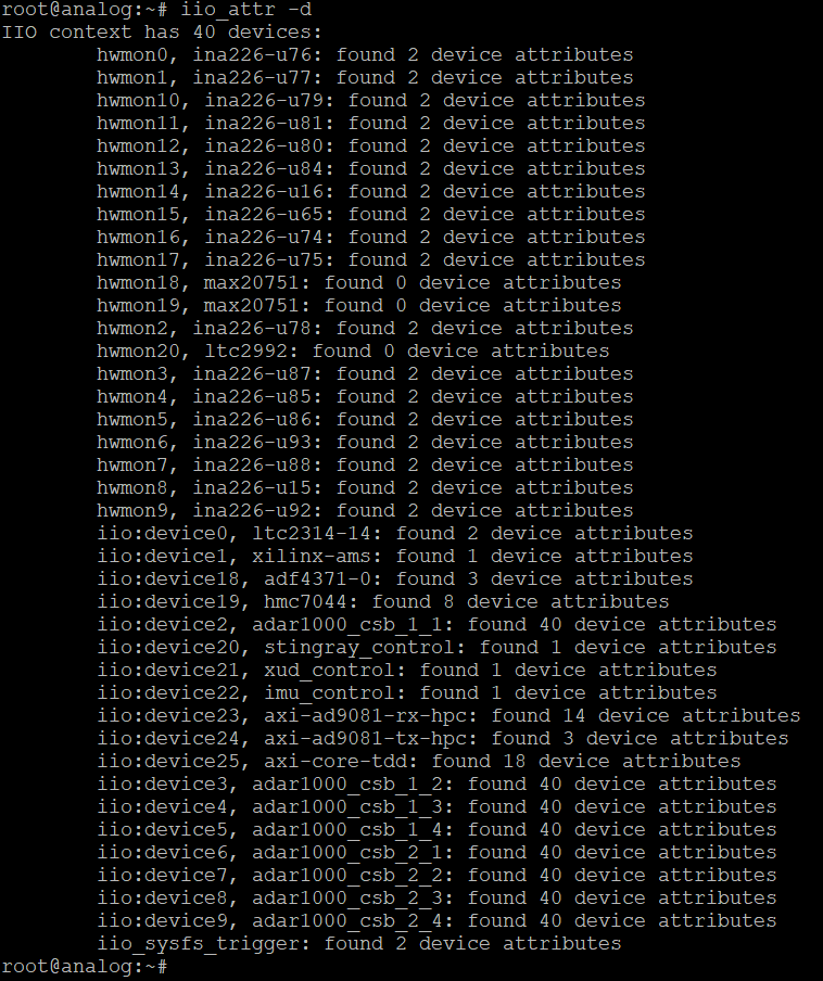
Check IIO devices:
root@analog:~# iio_attr -d
You should see 40 IIO devices listed
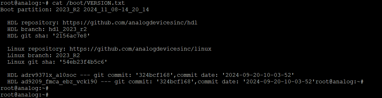
Verify Kuiper version:
root@analog:~# cat /boot/VERSION.txt
Confirm it matches your downloaded image version
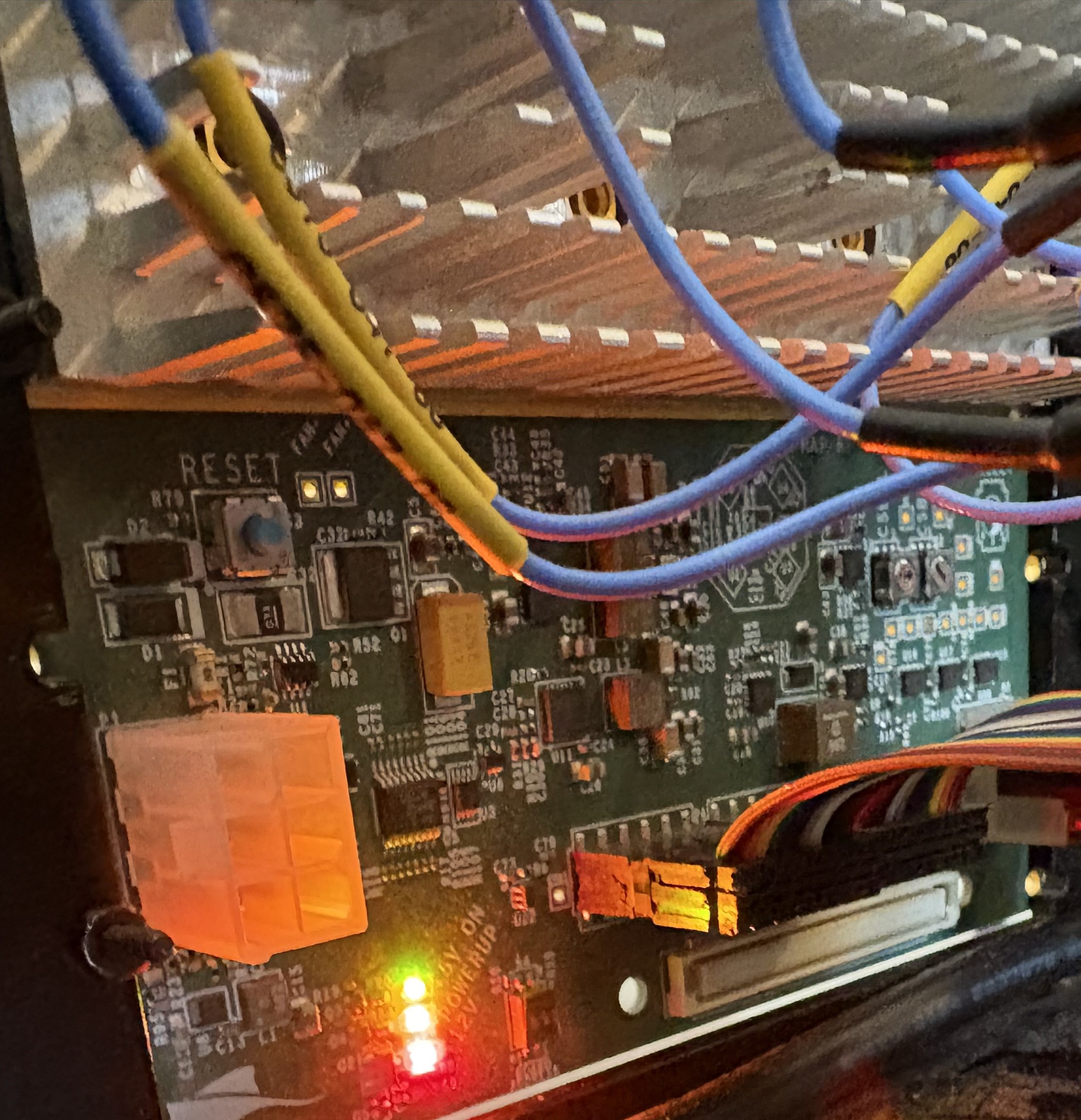
Verify Stingray LED status:
Inspect the Stingray board and confirm the following LEDs are illuminated:
Red LED: Power good
Yellow LED: System activity
Green LED: Boot complete
All three LEDs lit simultaneously confirm a successful boot
Tip
Boot is confirmed successful when 40 IIO devices appear in the terminal and the red, yellow, and green LEDs are all illuminated on the Stingray board. Your SD Card is properly configured and ready for use with MATLAB/Python scripts.
Additional Resources
See also
ZCU102 Configuration - Configure boot mode and peripherals
EEPROM Programming - Program FMC EEPROM for proper VADJ
Assembly Guide - Complete hardware assembly instructions