DE10-Nano Quick start
This guide provides some quick instructions on how to setup the EVAL-AD719x-ASDZ on:
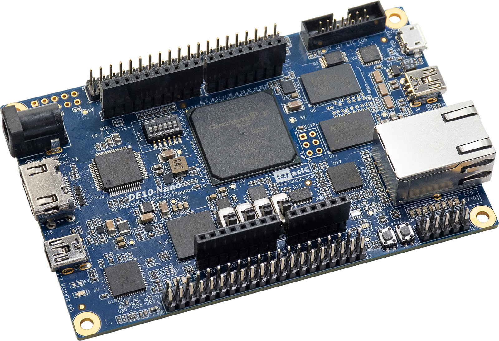
DE10-Nano Arduino shield connector
Using Linux as software
Necessary files
The following files are needed for the system to boot:
HDL boot image: preloader, bootloader, FPGA bitstream
Linux Kernel image:
zImageLinux device tree:
socfpga.dtbextlinux/extlinux.conf
They can either be taken from the SD card – already generated by us, or you can build them manually.
In the following sections, we explain how to take them from the SD card.
Instructions on how to manually build the boot files from source can be found here:
AD719X-ASDZ HDL project build documentation. More HDL build details at Build an HDL project.
Required Software
SD Card 16GB imaged with Kuiper Linux
An UART terminal (Putty/Tera Term/Minicom, etc.) with baud rate 115200 (8N1)
Required Hardware
One of the EVAL-AD719x-ASDZ evaluation boards
Micro SD card with at least 16GB
Mini USB to USB Type A cable (UART)
5V/2A Wall Power supply with barrel jack (comes with DE10-Nano)
LAN cable (Ethernet)
Testing
Creating the setup
All the products described on this page include ESD (electrostatic discharge) sensitive devices. Electrostatic charges as high as 4000V readily accumulate on the human body or test equipment and can discharge without detection. Although the boards feature ESD protection circuitry, permanent damage may occur on devices subjected to high-energy electrostatic discharges. Therefore, proper ESD precautions are recommended to avoid performance degradation or loss of functionality. This includes removing static charge on external equipment, cables, or antennas before connecting to the device.
Follow the steps in this order, to avoid damaging the components:
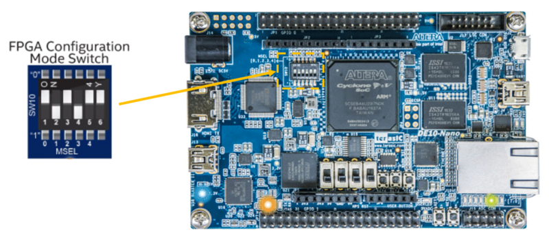
Verify that the FPGA Configuration Mode Switch (S10) on the DE10-Nano is configured properly. See the image below for the proper configuration, and if more information is needed, check out the DE10-Nano Getting Started Guide.
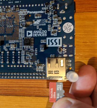
Insert the SD card with ADI Kuiper image into the microSD card slot on the DE10-Nano
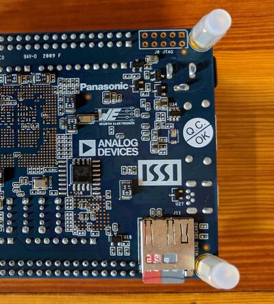
Using the Arduino shield connector, connect the EVAL-AD719x-ASDZ on top of the DE10-Nano
Connect USB UART (Mini USB) to your host PC
Connect an Ethernet cable to the DE10-Nano and to your network
Connect the 5V power supply and power up the setup
Info
If you don’t have a network available and want to stream data directly from the Ethernet port of the DE10-Nano to the Ethernet port of your PC, that is still possible, but requires some extra configuration. Please see the Network Configuration page for complete details.
DE10-Nano SD card boot files
The files that need to be present on the SD card BOOT partition are:
Preloader, bootloader, FPGA bitstream
zImagesocfpga.dtbextlinux/extlinux.conf
Copy these from the socfpga_cyclone5_de10_nano_cn0540 folder on the SD card
imaged with the ADI Kuiper image.
Setting up UART
A driver for the board should automatically be detected and installed on your PC. If this does not happen, you may need to manually install the driver. Here is a link to the UART Serial Driver.
Using your Device Manager, locate the COM port assigned to the DE10-Nano board.
Open PuTTY, Tera Term, or another serial terminal program and open a terminal to the COM port of the DE10-Nano by setting the baud rate to 115200, then connect.
The serial terminal connection will auto-login and place you in the root directory of the SD card.
Boot messages
The following is what is printed in the serial console, after you have connected to the proper ttyUSB or COM port:
<placeholder>
Useful commands for the serial terminal
The below commands are to be run in the serial terminal connected to the board.
To find out the IP of the board, run the following command and take the IP specified at “eth0 inet”:
~$
ifconfig
To power off the system, run the following command, and wait for the final message to be printed, then power off the board from the switch as well.
~$
poweroff
To reboot the system, run:
~$
reboot
Important
Even thought this is Linux, this is a persistent file systems. Care should be
taken not to corrupt the file system – please shut down things, don’t just
turn off the power switch. Depending on your monitor, the standard power off
could be hiding. You can do this from the terminal as well with
sudo shutdown -h now or the above-mentioned command for powering off.
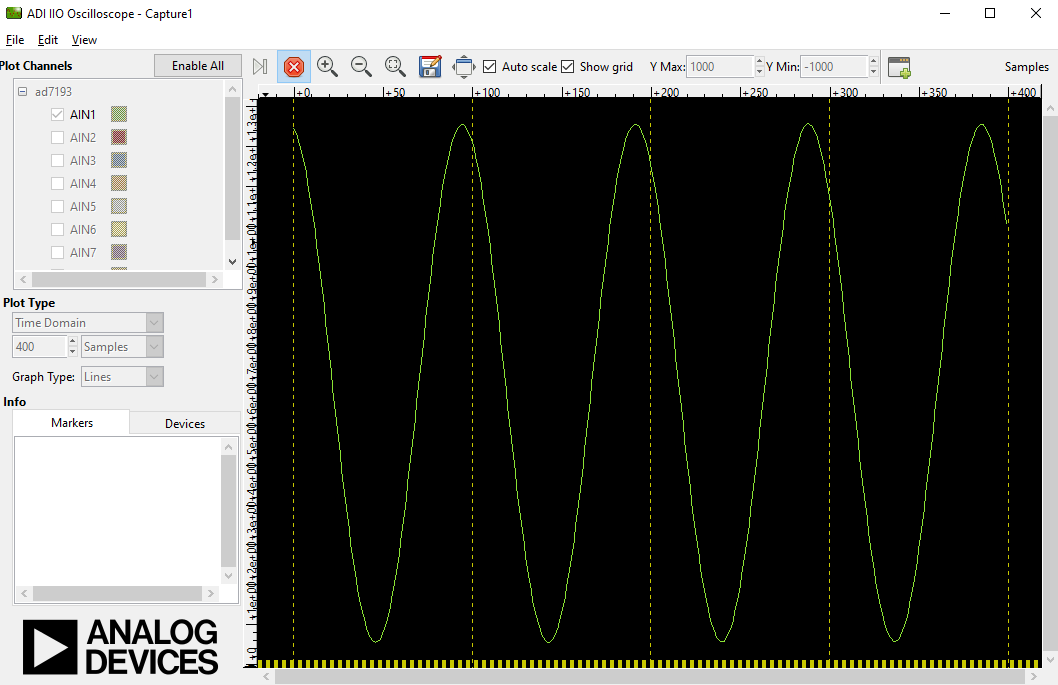
Using the System with IIO Oscilloscope
The IIO Oscilloscope is a cross-platform application for interfacing with IIO devices, enabling you to configure device parameters and visualize data.
Important
Make sure to download/update to the latest version of IIO Oscilloscope.
Remote run on host
The IIO Oscilloscope application can be used from a host PC to connect to the board over the network, configure the device, and read data.
Build and start osc on a network-enabled Linux host. For Windows
computers, open the application from the start menu.
Once the application is launched, go to Settings > Connect > URI
and type ip: followed by the IP address of the board. This IP can
be found with the ifconfig command from the serial terminal.
Please see IIO Oscilloscope documentation for installation steps and more details.
Locally run on the board
If you have a display connected to the board (via HDMI or VNC), you can
run IIO Oscilloscope directly on the board. Open a terminal and launch
osc, or find it in the application menu. It will automatically
connect to the local IIO devices.
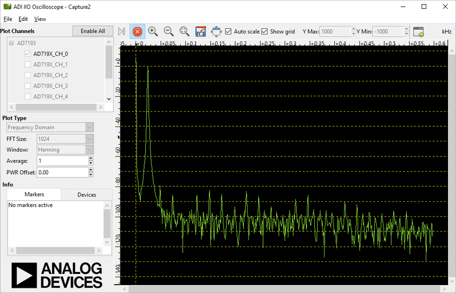
Time Domain Plot
Frequency Domain Plot
Note
Max 4096 samples can be selected for plotting frequency domain response due to limited buffer size in the firmware.