AD7606 Mbed IIO Application
Introduction
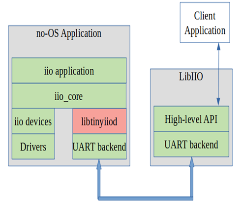
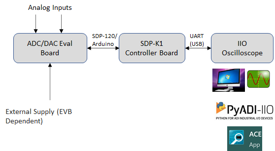
This page gives an overview of using the ARM platforms supported (default is Mbed) firmware application with Analog Devices EVAL-AD7606 evaluation board(s) and SDP-K1 controller board. This example code leverages the ADI developed IIO (Industrial Input Output) ecosystem to evaluate the AD7606 family devices by providing a device debug and data capture support.
The IIO Oscilloscope acts as the client application on a Windows OS, providing a GUI for ADC data visualization and device configuration and debug. The SDP-K1 controller board hosts the IIO firmware, communicating with the AD7606 via ADI No-OS drivers and platform drivers. Communication between the board and the PC uses Virtual COM (VCOM) by default, with UART available as an alternative. The firmware has been developed and tested on SDP-K1, and is compatible with other Mbed-enabled boards with Arduino header support (e.g. STM32-Discovery, STM32-Nucleo).
Useful Links
AD7606C (shares same docs with AD7606B)
Hardware Connections
SDP-K1
Connect the VIO_ADJUST jumper on the SDP-K1 board to 3.3V position to drive SDP-K1 GPIOs at 3.3V
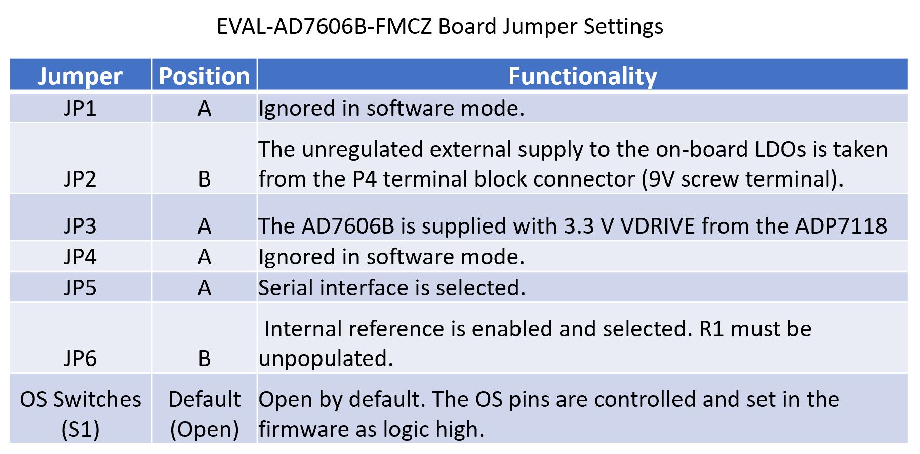
EVAL-AD7606B-FMCZ
Make the following jumper settings on the board. Refer to the EVAL-AD7606B-FMCZ User Manual for more details.
Arduino Connections
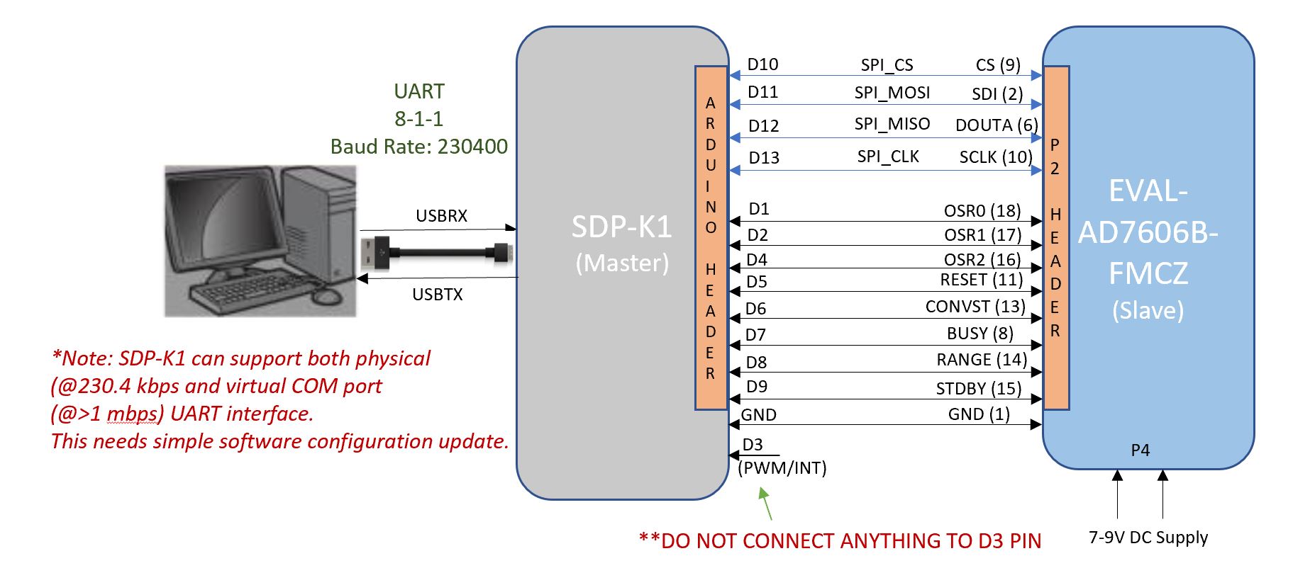
The AD7606 device is configured in “Serial Software” mode in the firmware. AD7606 uses SPI communication for device register access and data capture.
Data Transmission Interface
The SDP-K1 acts as a serial device when connected to a PC, creating a
COM port for the IIO Oscilloscope GUI. The default communication
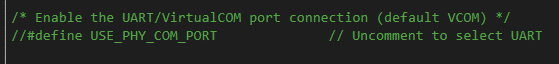
interface is Virtual COM (VCOM) at higher speed. UART is available as
an alternative by setting the USE_PHY_COM_PORT macro in
app_config.h. Both interfaces are powered via the USB connection
from the host computer.
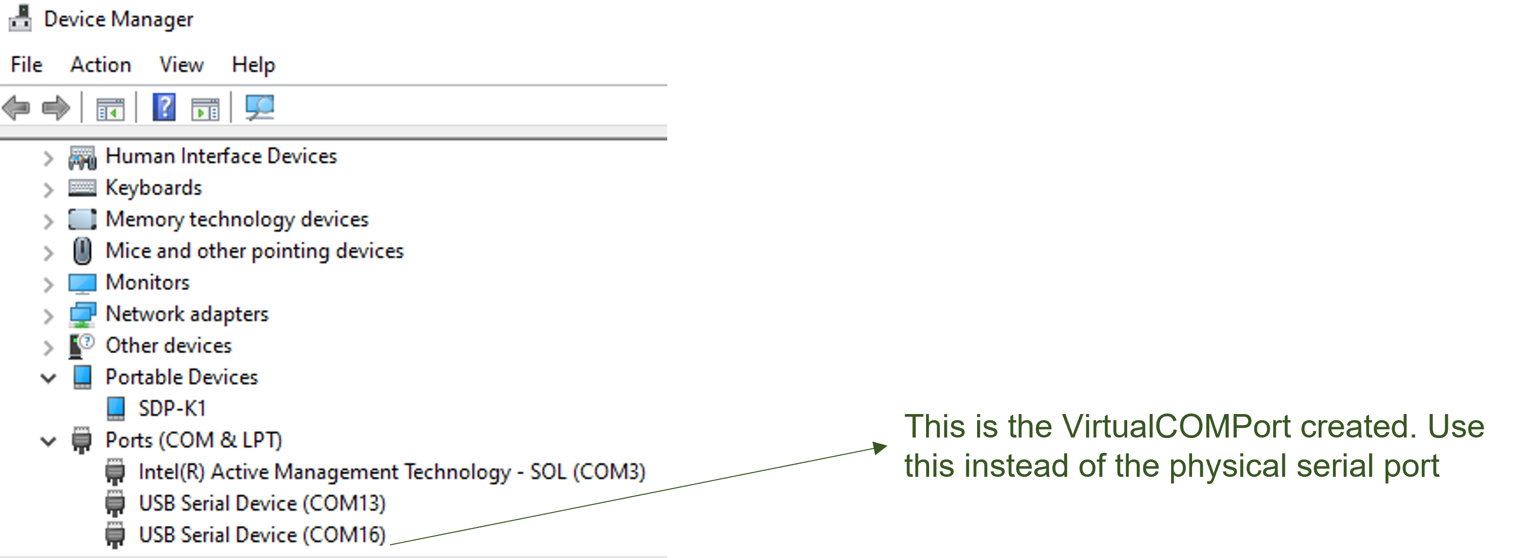
The COM port assigned to the SDP-K1 can be found using Windows Device Manager.
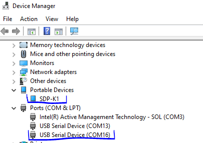
Important
The actual COM port number for your device may not be the same as shown above. Always check your SDP-K1 serial COM port number in Device Manager before connecting to the IIO client.
Software Downloads
MBED Firmware
The firmware source code is available on GitHub. Refer to the repository README for build instructions.
Download
Libiio: IIO Library
This library provides an abstracted interface for communication between the IIO device and the IIO Oscilloscope client, without requiring knowledge of low-level hardware details.
Download
IIO Oscilloscope (Client)
This is a GUI-based IIO client application for data visualization and device configuration and debugging. Data from IIO devices is transmitted over Serial/Ethernet/USB link to the IIO Oscilloscope through the abstracted “libiio” layer.
Evaluating AD7606 Using IIO Ecosystem
Note
Ensure hardware connections are properly set up and all software (IIO firmware, Libiio, and IIO Oscilloscope) is installed before proceeding.
Running IIO Oscilloscope (Client)
Open the IIO Oscilloscope application from the start menu
Configure the serial (UART) settings as shown below
Click on the refresh button and the AD7606 device should appear in the IIO devices list
Click ‘Connect’ and select the AD7606 device from the ‘Device Selection’ drop-down menu
Configure/Access Device Attributes (Parameters)
The IIO Oscilloscope allows users to access and configure different device parameters, called ‘Device Attributes’. There are 2 types of attributes:
Device Attributes (Global): Access/Configure common device parameters e.g. oversampling rate, operating mode
Channel Attributes (Specific to channels): Access/Configure channel specific device parameters e.g. channel range, offset, calibration, open circuit detection, etc.
How to read and write attributes:
To ‘Read’ an attribute: Select the attribute from the list or press the ‘Read’ button on the left side.
To ‘Write’ an attribute: Enter a value in the ‘value field’ and press the ‘Write’ button. The value corresponds to the expected bit-field for that parameter, as specified in the datasheet. The figure below shows how to write an “Oversampling” value.
Using DMM Tab to Read DC Voltage on Input Channels
The DMM tab can be used to read the instantaneous voltage applied on analog input channels. Simply select the device and channels to read and press the start button.
Note
The voltage is just instantaneous, so it is not possible to get RMS AC voltage or averaged DC voltage. Also, when using the DMM tab, it is not encouraged to use the Data Capture or Debug tab as this could impact data capturing.
Data Capture from IIO Device
To capture data from the AD7606 IIO device, select the device and channels to read. The data is plotted as “ADC Raw Value” vs “Number of Samples” for visualization. The data is read as-is from the device without any processing. To process the data, capture it externally from the serial link on the controller board.
Note
The DMM or Debug tab should not be accessed when capturing data as this could impact data capturing.
Important
The continuous time-domain data capture can work correctly at ODR/Sampling Rate defined in the firmware code (32 kSPS) and also at 0 Oversampling Rate. For plotting frequency domain response, a maximum of 4096 samples can be selected due to limited buffer size in the firmware. These limitations are due to firmware architecture and design choices and do not limit the actual device specifications provided in the device datasheet.
Time Domain Data Capture
Frequency Domain Data Capture
Calibrating AD7606B/C Devices
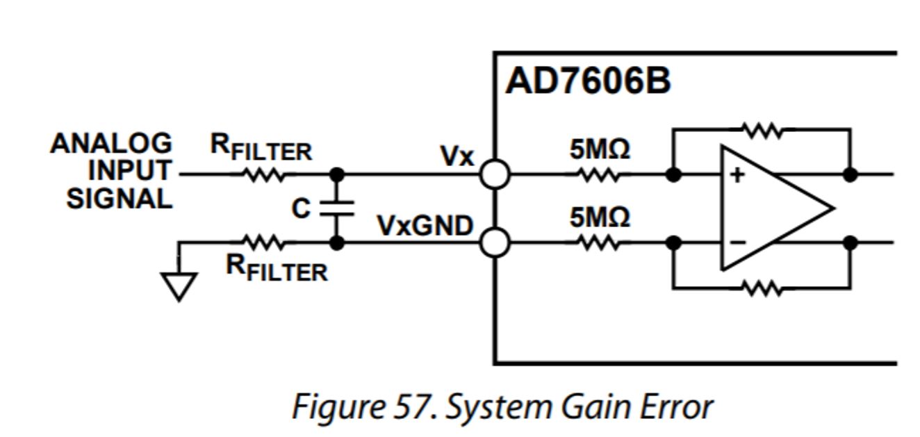
ADC Gain Calibration
ADC gain calibration can be done in 3 easy steps. The gain calibration needs to be done for the selected gain filter register as specified in the datasheet (refer ‘System Gain Calibration’ section from the AD7606B/C datasheet). The gain calibration can be done for each channel depending upon the filter resistor placed in series with each channel analog input.
Reference: File: iio_ad7606.c,
Function: get_chn_calibrate_adc_gain()
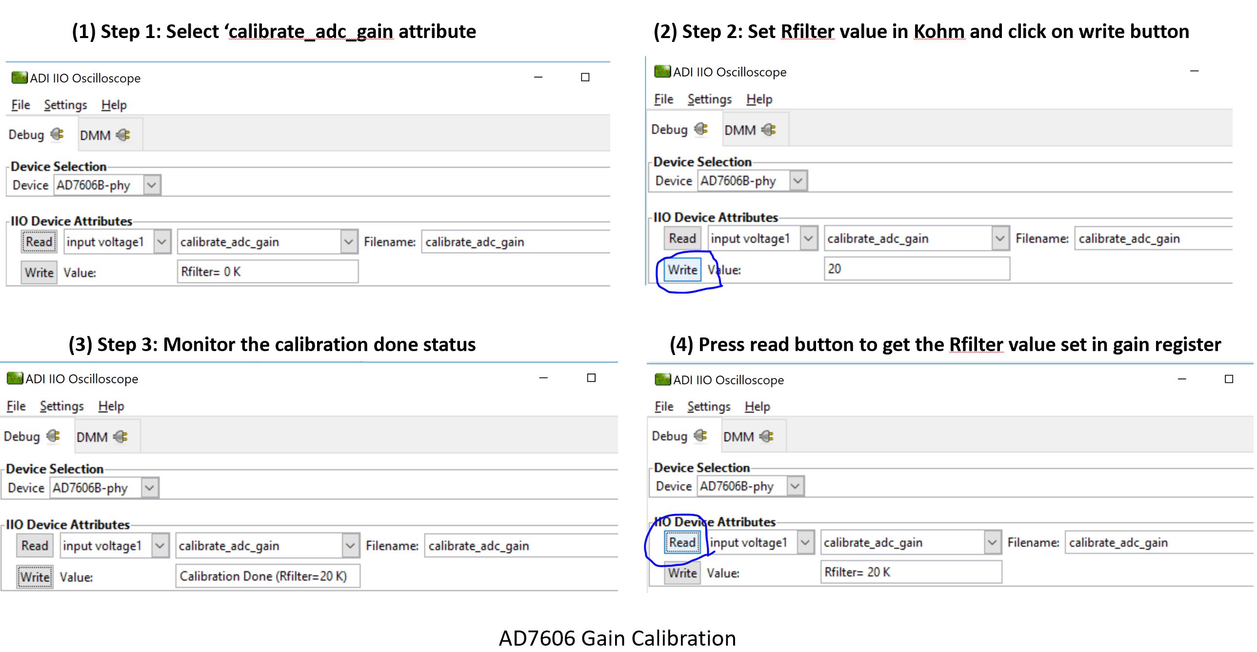
ADC Offset Calibration
ADC offset calibration should only be done when ADC input is 0V. The purpose is to reduce any offset error from the input when the analog input is at 0V level. The ADC offset calibration can be done for each input channel.
To perform ADC offset calibration:
Select the ‘calibrate_adc_offset’ attribute
The calibration will be performed automatically
Pressing the ‘Read’ button will trigger calibration again
Reference: File: iio_ad7606.c,
Function: get_chn_calibrate_adc_offset()
Open Circuit Detection on AD7606B Device
The AD7606B provides an open circuit detection feature for detecting open circuits on each analog input channel. There are 2 modes:
Manual Mode
Auto Mode
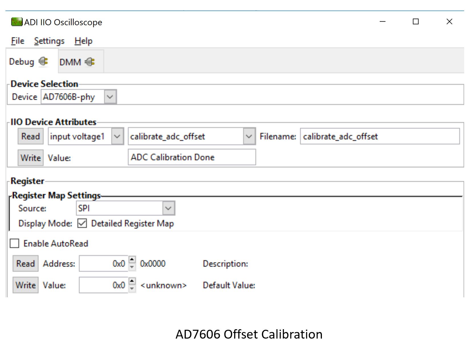
Manual Mode Open Circuit Detect
The manual open circuit detection requires an ‘Rpd’ resistor at the analog input, as shown in the figure below. The firmware is written to perform open circuit detection at 50 kΩ Rpd value. The common mode change threshold is defined as 15 ADC counts in the firmware at the specified configurations (as per the datasheet).
Reference: File: iio_ad7606.c,
Function: get_chn_open_circuit_detect_manual()
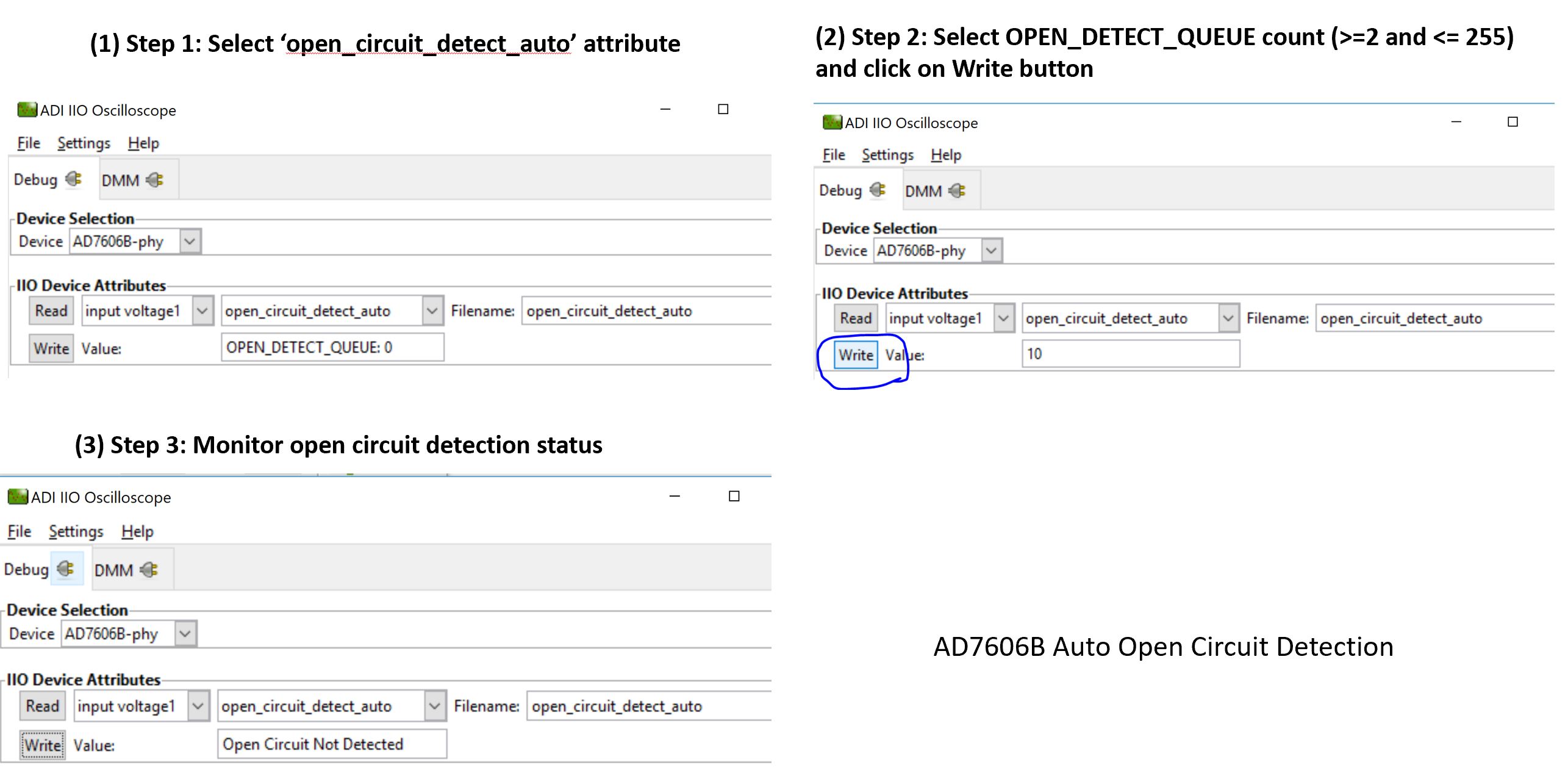
Auto Mode Open Circuit Detect
The auto open circuit detection on each individual ADC channel can be done by performing 3 easy steps as shown in the screenshot below.
Reference: File: iio_ad7606.c,
Function: get_chn_open_circuit_detect_auto()
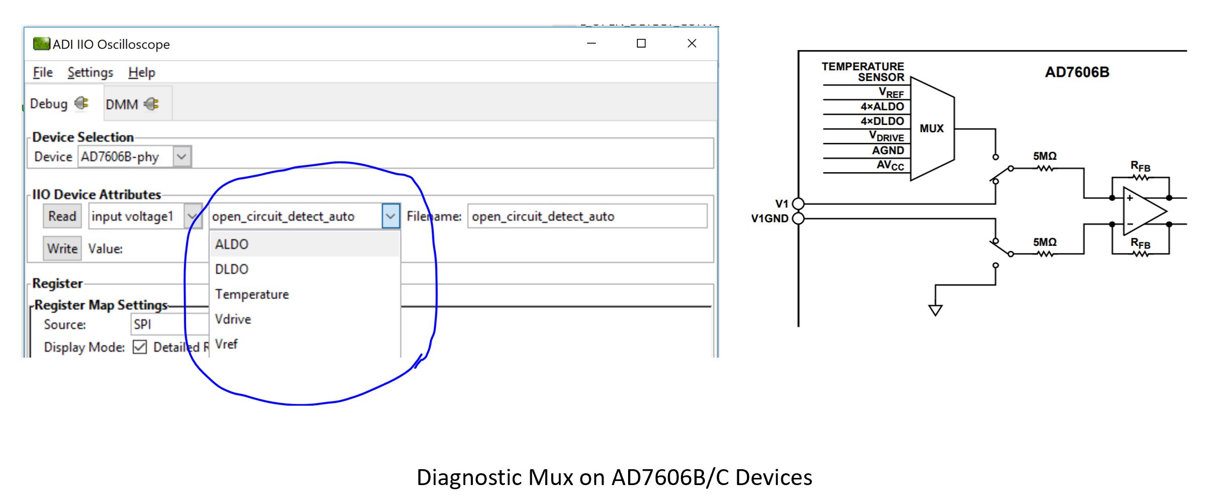
Diagnostic Multiplexer on AD7606B/C Devices
Using the diagnostic multiplexer on AD7606B/AD7606C devices, the internal analog inputs can be sampled to provide diagnostic voltages and parameters on the IIO client application such as:
Reference voltage (Vref)
DLO voltage (ALDO/DLDO)
Temperature
Drive voltage (Vdrive)
Note
The diagnostic mux control must operate when input range is ±10V.
Python Environment and Scripts
Data capture can be achieved with Python-based IIO clients using the ‘pyadi-iio’ library. The Python scripts are provided along with the firmware package.
Setting up Python Environment
Install Python from python.org/downloads. Python 3.9.0 or later is recommended.
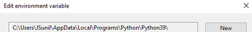
Ensure the Python executable is added to the Windows environment path.
Verify the installation by running
python --versionin a terminal (e.g. Command Prompt, PowerShell, or Git Bash):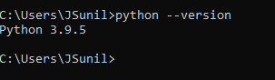
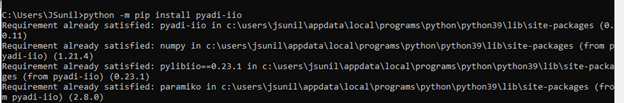
Install the
pyadi-iiopackage. A detailed guide is available at pyadi-iio.python -m pip install pyadi-iio
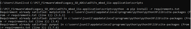
Install additional dependencies from the
scripts/directory:python -m pip install -r requirements.txt
Modifying/Running Python Scripts
All Python scripts are stored in the scripts/ folder in the project
directory and must be executed from that folder.
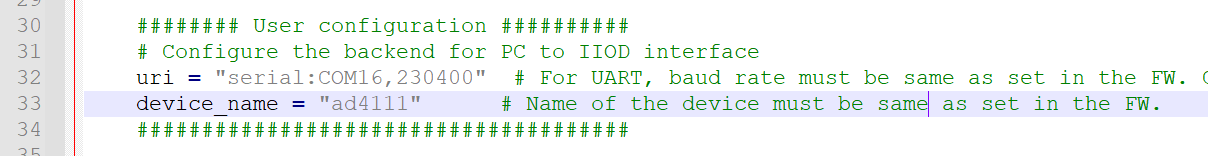
Update the uri interface in the script to match the COM port
assigned to the SDP-K1. The default is COM16 in all scripts.
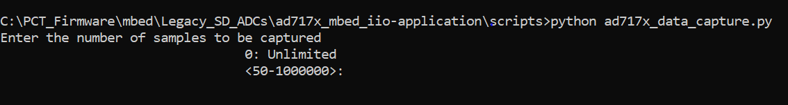
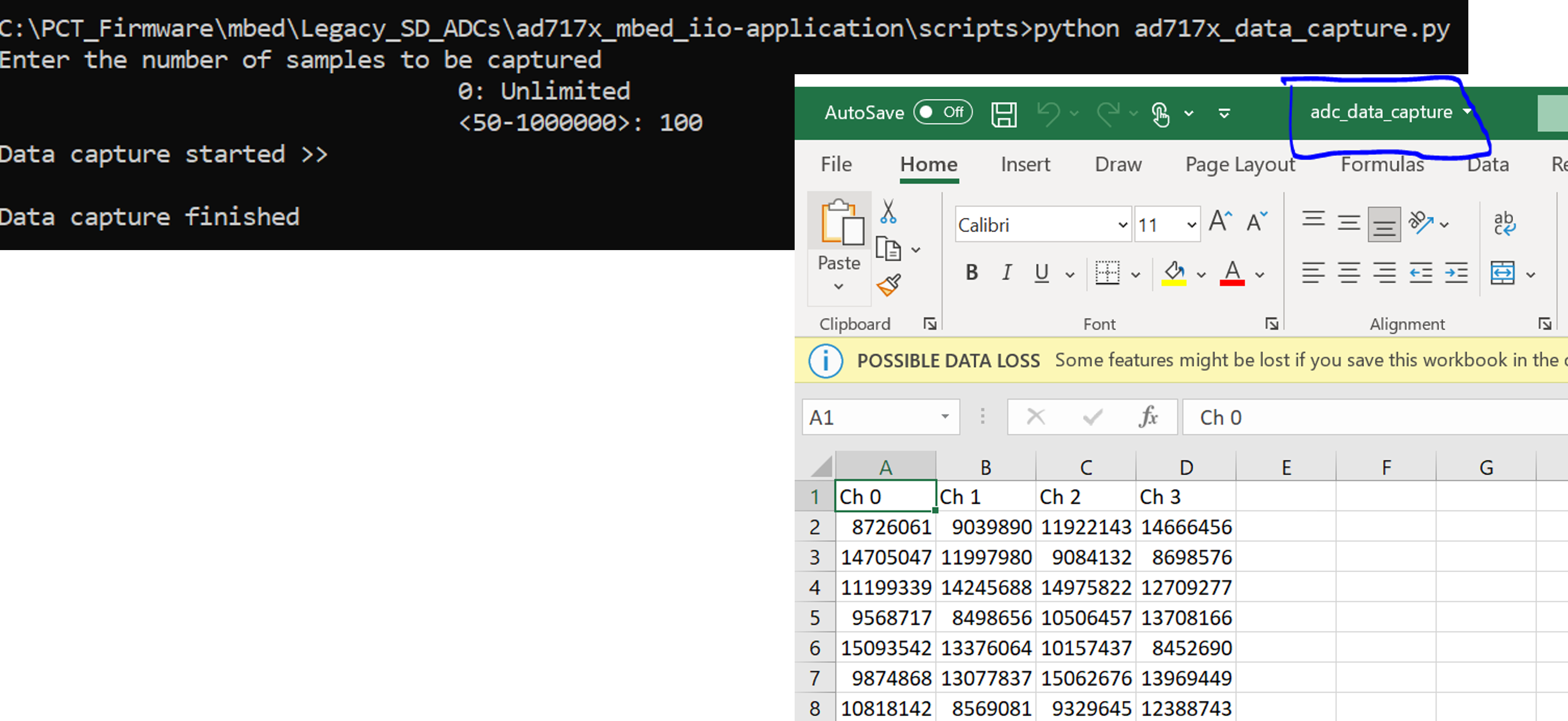
Output from Python Scripts
When executing the data capture script, the command prompt will request the number of samples:
On successful completion, data is stored in adc_data_capture.csv
in the scripts/ folder.
Modifying Firmware
The following block diagram shows the AD7606 IIO firmware layer:
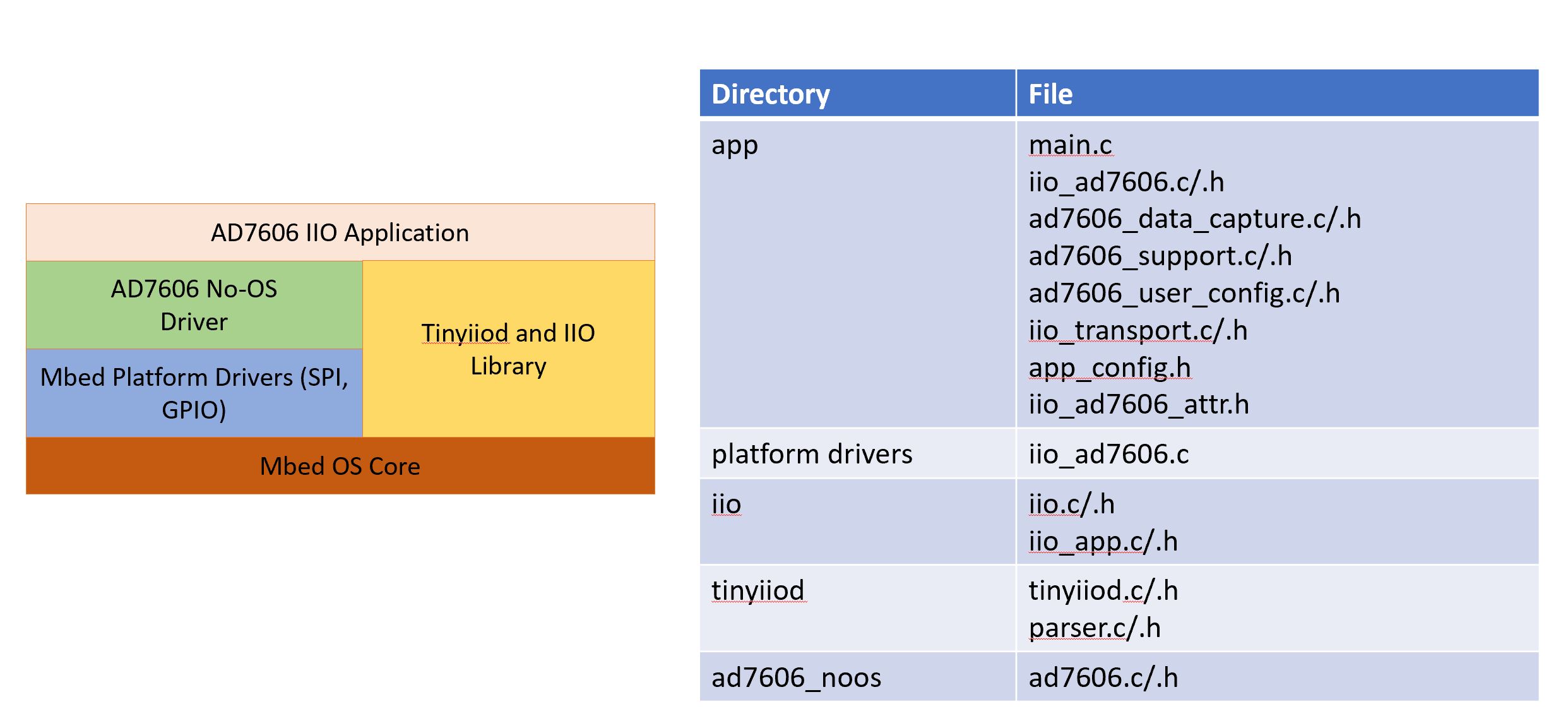
app_config.h
This file can be used to:
Select the ‘Active Device’ to evaluate by changing the
#define DEV_AD7606Bmacro. Default active device is AD7606B.Configure the pin mapping of AD7606 w.r.t Arduino Header on the Controller Board.
ad7606_user_config.c
This file defines the user configurations for the AD7606, such as SPI parameters (frequency, mode, etc) and other initialization parameters used by No-OS drivers to initialize AD7606 device (e.g. required GPIOs, software/hardware mode, etc). These are the parameters loaded into the device when it is powered-up or power-cycled.
iio_ad7606.c
This file defines getter/setter functions for all device and channel- specific attributes (related to AD7606 devices) to read/write device parameters. The majority of device-specific functionality is present in this module.
iio_ad7606_data_capture.c
This file defines the data capture implementation of AD7606 for visualizing ADC raw data on the IIO oscilloscope.
No-OS Drivers for AD7606
The No-OS drivers provide the high-level abstracted layer for the digital interface of AD7606 devices. The complete digital interface (to access memory map and perform data read) is done in integration with platform drivers. The functionality is covered in the following files:
ad7606.cad7606.h
Tip
It is hoped that the most common functions of the AD7606 family are coded, but it’s likely that some special functionality is not implemented. Feel free to consult Analog Devices Engineer-Zone for feature requests, feedback, and bug reports.