Production Testing
Overview
The purpose of the test procedure is to identify connectivity issues, poor soldering, and potential manufacturing defects. Some of the issues are directly identified by explicit part-targeted tests, others are implicit, by running adjacent tests.
Attention
Before running the production tests, the boards need FTDI programming. See FTDI Programming section below.
FTDI Programming
Before running the production tests, the boards need FTDI programming. Follow the steps below to program the FTDI.
Required Hardware
FTDI programming fixture (resistor board with programming area)
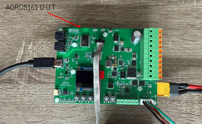
ADRD5161 board (D.U.T)
Load resistors
USB cable for connection to PC
Required Software
MAX77958 TypeC/PD & MAX77962 Charger EV Kit application
Firmware binary file (
.bin)
Programming Steps
No. |
Steps |
|---|---|
1 |
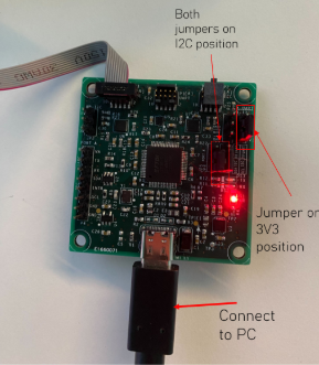
Set up the jumper positions on the programming fixture:
|
2 |
Connect the ADRD5161 board to the load as shown below: 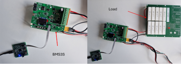
|
3 |
Connect the fixture to the PC via USB cable |
4 |
Open the MAX77958 TypeC/PD & MAX77962 Charger EV Kit application |
5 |
Go to Device > Connect to connect to the device. If scanning fails, a dialog will appear asking “Could not confirm existence of devices. Do you want to continue?” - click Yes to proceed 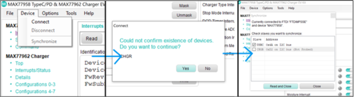
|
6 |
Once connected, go to Tools > Firmware Update… 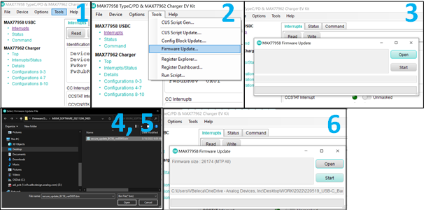
|
7 |
In the Firmware Update window:
|
8 |
Wait for the firmware to be written. A completion message will appear: “Write firmware data to the device…Completed.” 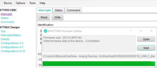
|
9 |
Verify the programming was successful by checking the LED feedback on the resistor board. Once the FTDI is programmed, the red LED must be ON 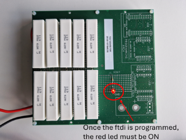
|
10 |
Disconnect the board from the application by going to Device > Disconnect 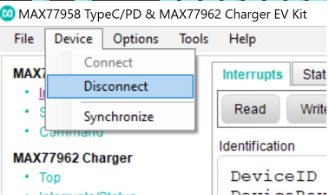
|
11 |
Remove the board from the fixture and proceed with production testing |
Test Procedure
Test Duration
Step Description |
Estimated Time (minutes) |
|---|---|
Test bench setup |
5 min |
Software test |
6 min |
Total time |
11 min |
Required Hardware
ADRD5161 board as Device Under Test
Raspberry Pi, HDMI cable, power supply, mouse and keyboard
Power supply USB C (20V, 5A)
MAXPICO 32650 programmer (Daplink)
CAN2USB cable
Battery
Resistor board
Required Software
The test image will be provided as a SD test card that goes into the Raspberry Pi.
Test Setup
No. |
Steps |
|---|---|
1 |
Insert the SD card into the Raspberry Pi |
2 |
Connect the Raspberry Pi to a monitor and power it |
3 |
Connect the Daplink programmer to the D.U.T and the Raspberry Pi 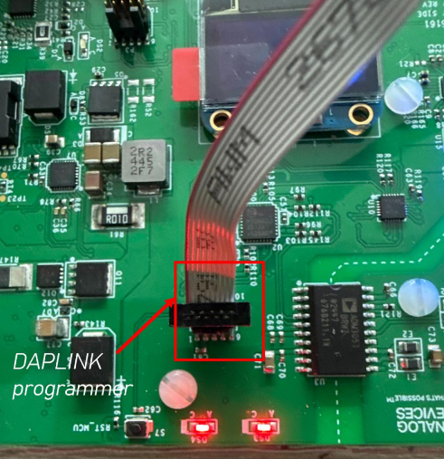
|
4 |
Connect the CAN to USB cable to the D.U.T and the Raspberry Pi 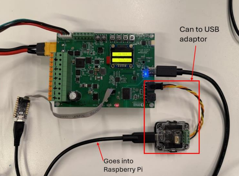
|
5 |
Connect the resistor board to -/+ on the DUT as seen in the picture below 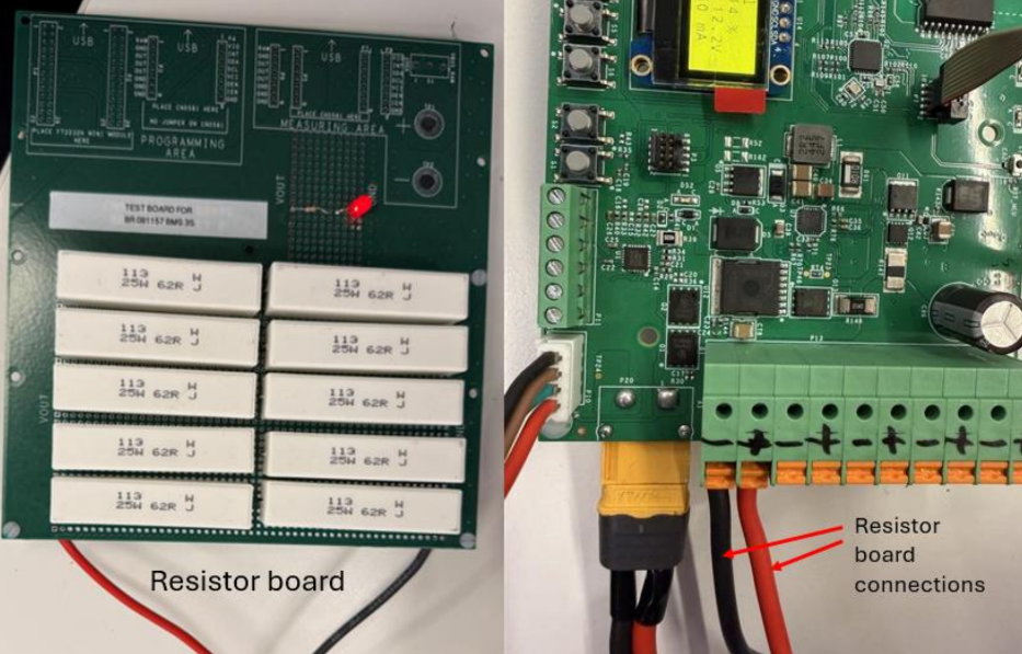
|
6 |
Connect the battery to XT60 connector on the D.U.T and the balancing connector (picture below) 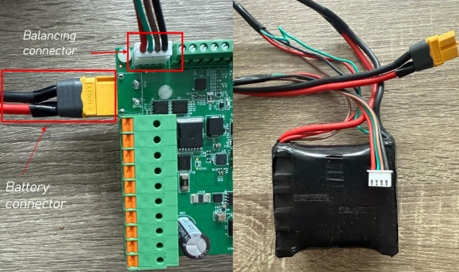
|
7 |
Connect the power supply USB C into the D.U.T 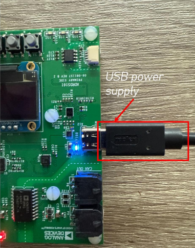
|
Enabling Wifi
Before starting the testing procedure, make sure the Raspberry Pi is connected to Wifi.
After the RPi boots, press CONTROL+C to exit the test screen
Click on the Wifi network you want to connect to
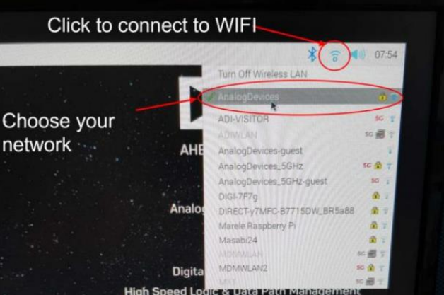
Type in the password
After connecting successfully, reboot the Raspberry Pi by following the instructions below:
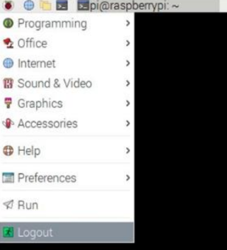
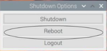
Running the Test Software
After reboot, the following test menu should appear:
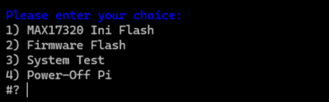
Please enter your choice:
1) MAX17320 Ini Flash
2) Firmware Flash
3) System Test
4) Power-Off Pi
1) MAX17320 Ini Flash
Type “1” into the terminal and press ENTER to start 1) MAX17320 Ini Flash.
Please verify that the programmer is connected to header P7, then press Enter.
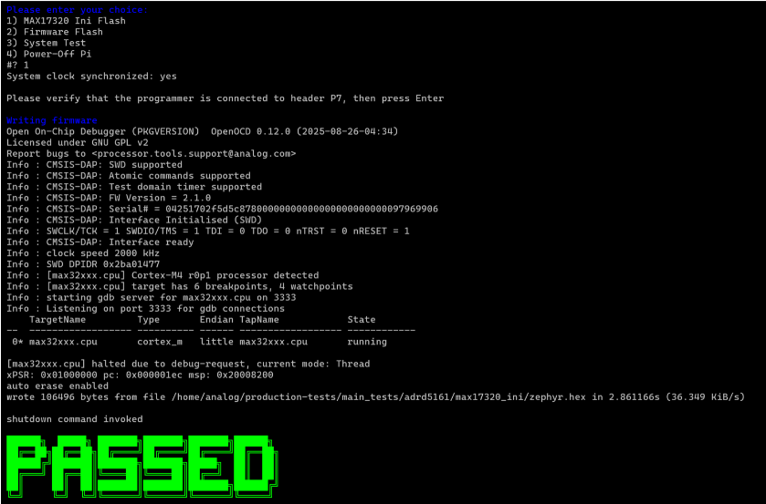
After the first test is passed, move on by writing “2” in the terminal.
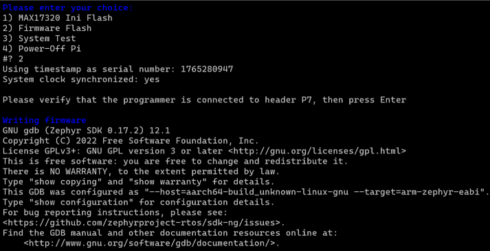
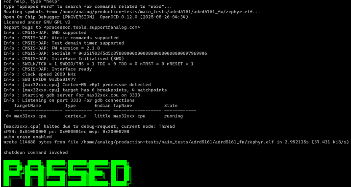
2) Firmware Flash
Type “2” into the terminal and press ENTER to start 2) Firmware Flash.
Please verify that the programmer is connected to header P7, then press Enter.
3) System Test
Type “3” in the terminal in order to run 3) System Test.
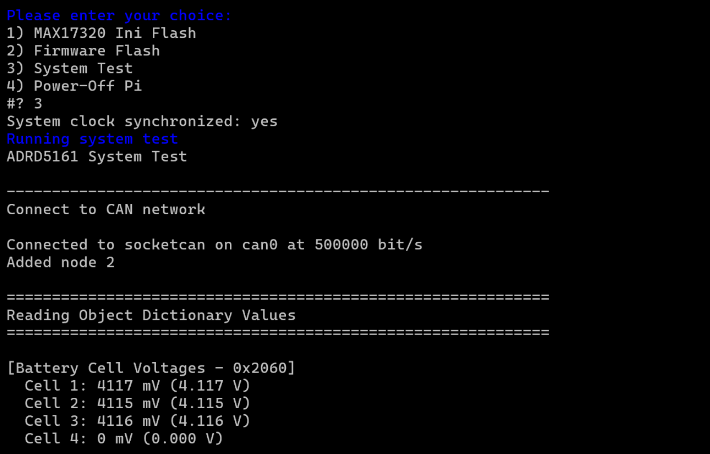
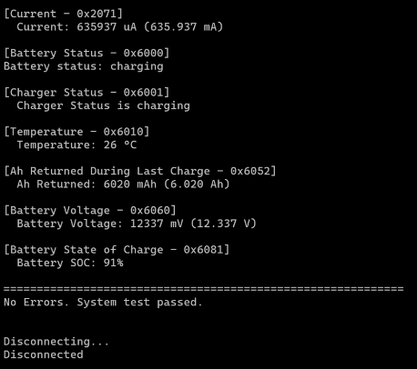
If no errors are found, the message “No Errors. System test passed.” will be displayed.
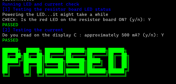
Next, you will need to unplug the USB C power supply from the D.U.T. When prompted, check if the red LED is on (see picture below) and type y or n.
For the current test, read the display on the board. The value should be approximately 500 mA. If around that value, type y.
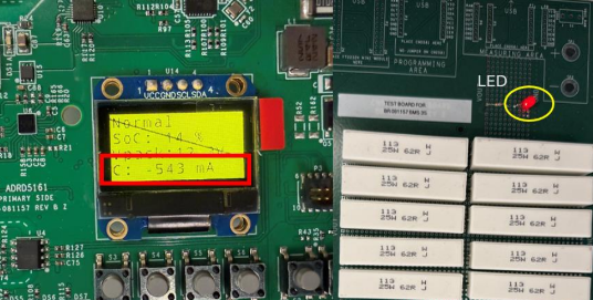
After all tests pass, a green PASSED message will appear on the screen.
Warning
If a FAILED message appears, check the connections and verify that all cables are properly connected. You may repeat the failed test if it was due to a connection issue.
4) Power-Off Pi
When you are done testing, press “4” and press ENTER to power-off the Raspberry Pi.
Pass Criteria
MAX17320 Ini Flash: Test 1) has successfully passed
Firmware Flash: Test 2) has successfully passed
System Test: Test 3) has successfully passed with LED verification and current reading approximately 500 mA