Transceiver Evaluation Software (TES)
ADRV9002 uses profiles to designate different device configuration settings for the Tx/Rx channels. The profile dictates how the digital filters, analog filters, clock rates, and clock dividers are configured in the device. Some specific parameters set by profiles include the IQ data rate, ADC clock rate, analog filter corners, FIR filter coefficients, and interpolation/decimation factors in the half-band filters. The TES software cannot connect directly to Jupiter, it is used to create a profile that will have corresponding .bin and .json files that can be uploaded to Jupiter.
Jupiter ships with a standalone profile pre-loaded: Navassa_LVDS_profile.json
If you are doing the MCS Sync Pilot (found later in this guide), you will need the MCS profile instead: MCS_30_72_CLK_AND_RATE.json
To make a different profile, you will need to install TES (on a Windows computer), and then use TES to produce the required .json/.bin files. TES calls the stream image a .bin file, while Scopy saves it as a .stream file. These are the same format with a different extension and can be used interchangeably. The rest of this page will walk through those procedures.
Installing TES
Go here and scroll down on the table until you see the ADRV9002 transceiver part
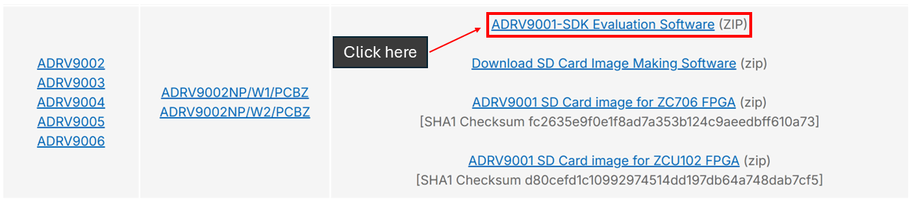
Click on this and download the ADRV9001-SDK Evaluation Software zip folder
This will download the ADRV9001 software development kit, which has TES in it
Navigate to the folder:
\adrv9001-sdk-eval-software\adrv9001-sdk.0.29.0\adrv9001-sdk\pkg\evaluation
and run ADRV9002 Transceiver Evaluation Software setup as administrator

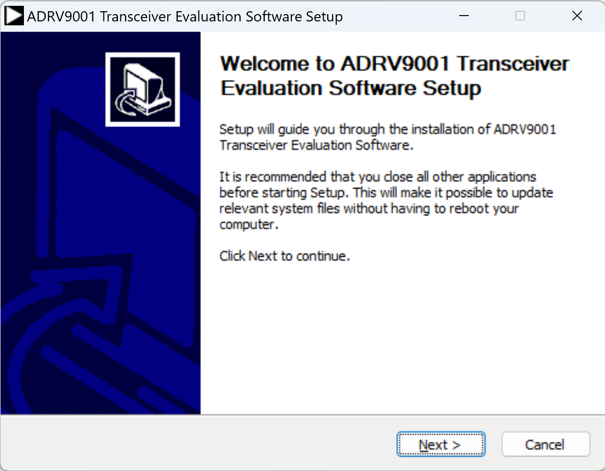
Now the setup wizard will pop up. Press Next on all screens, then install.
Using TES
This section will give a high-level overview of some of the configuration pages in TES. For a more in depth guide on TES see here.
Connection
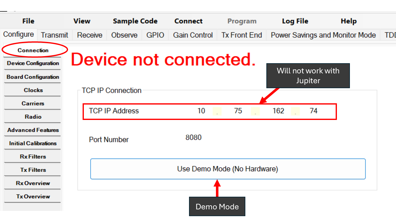
The TES software cannot connect directly to Jupiter, it is used to create a profile that will have corresponding .bin and .json files that can be used to configure Jupiter. This section will give a high level overview of some of the important features to consider when creating a profile in TES, as well as how to generate the .bin and .json files to be uploaded.
The first page that shows when opening TES is the connection page, inputting the Jupiter’s IP address will not work here. However, Demo Mode can be used to observe the profile.
Device Configuration
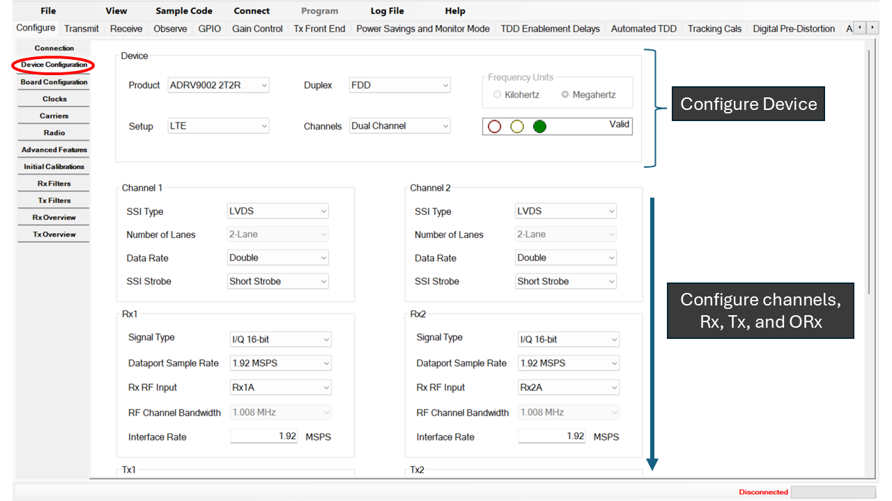
Device Configuration allows for Tx/Rx customization. There are some rules about how things can be configured. If there is an invalid configuration, TES will let you know in the device section.
Board Configuration
This page covers External Loopbacks, SSI Reference Clocks, and External LNAs.
Clocks
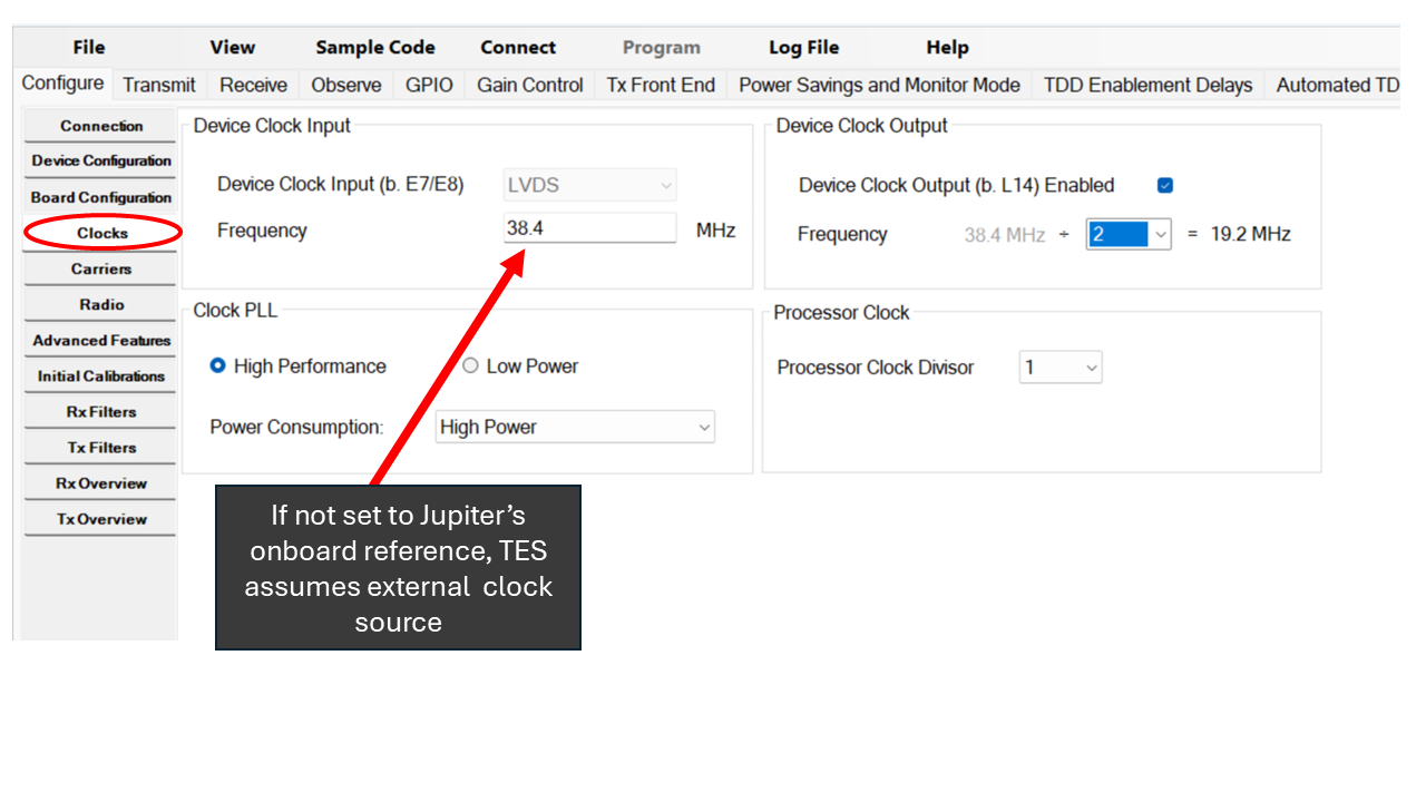
Whether Jupiter uses an external or internal reference clock is inferred by frequency the Device Clock is set to. Jupiter’s internal clock can be used if the frequency set corresponds to Jupiter’s onboard reference. If not, Jupiter will require an external reference with the profile. The clocks page exposes the Device Clock Input as well as the Clock PLL.
Advanced Features
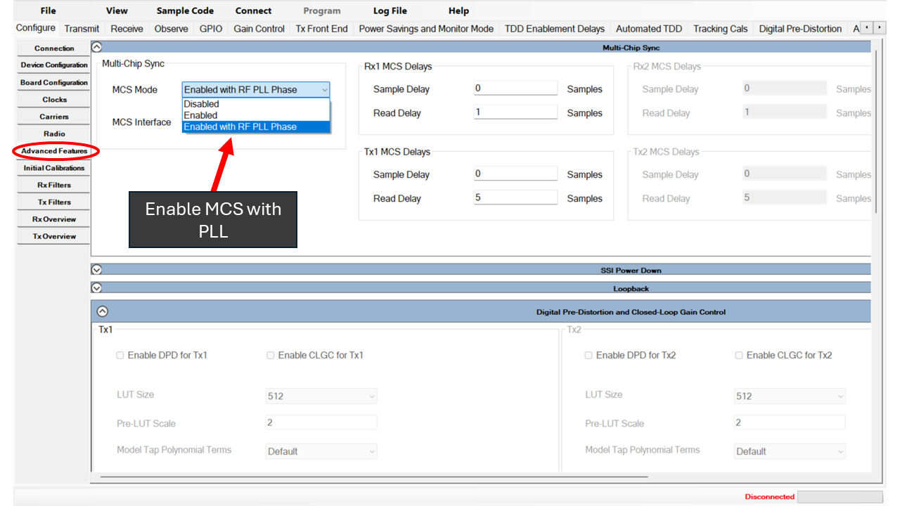
The Advanced Features tab has sections for Multi-Chip Sync, SSI Power Down, Loopback, Digital Pre-Distortion + Closed-Loop Gain Control, Monitor Mode, Stream Status Output over GPIO, and Receive Port Impedance Control.
Generating .bin and .json Files
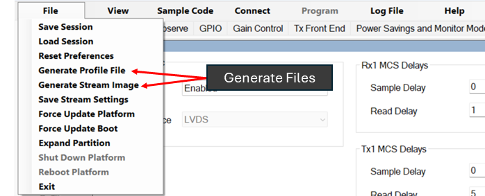
To create the .bin file: File -> Generate Stream Image
To generate the .json file: File -> Generate Profile File
Uploading .bin and .json Files
The .bin and .json files need to be put in the stream_config and the profile_config location, respectively. There are several ways to do this; the recommended method is to use Windows Powershell to copy the files into the directory, then cat them into the config locations. In order to do the MCS Pilot, MCS Mode drop-down must be set to ‘Enabled’ or ‘Enabled with RF PLL Phase’.
CD to the directory of the .bin and . json file
Run these commands to copy the files to a directory inside of Jupiter:
scp bin_file_name.bin root@<JUPITER_IP>:/root/
scp json_file_name.json root@<JUPITER_IP>:/root/
You will be prompted to enter the password; it is “analog”
To upload the file to the correct config locations:
ssh root@<JUPITER_IP> "cat /root/bin_file_name.bin > /sys/bus/iio/devices/iio:device1/stream_config"
ssh root@<JUPITER_IP> "cat /root/json_file_name.json > /sys/bus/iio/devices/iio:device1/profile_config"
Alternatively, if you do not want to use the command line, you can upload the .bin and .json files through the Controls tab in Scopy. Under “Profile & Stream Configuration”, use the file browser icons to load the .bin (stream) and .json (profile) files directly. See the Scopy documentation for details.
Warning
The profile loaded at boot must be compatible with the SD card image, or Jupiter will not boot.
The standalone and MCS images have different FPGA configurations (split DMA vs shared DMA) and different clock requirements (internal vs external reference). If the boot profile does not match what the image expects, the device will fail to initialize.
A standalone image expects a standalone profile (e.g.,
Navassa_LVDS_profile.json) and can use Jupiter’s internal clock.An MCS image expects an MCS profile (e.g.,
MCS_30_72_CLK_AND_RATE.json) and requires an external reference clock.
This only applies to the profile that loads at boot (stored in /lib/firmware/ on the SD card). Profiles uploaded at runtime through Scopy or SSH change the transceiver configuration but do not affect the underlying FPGA/DMA topology, which is why they are more forgiving and can work across either image type.
Creating an MCS Profile
This section walks through the minimum TES settings needed to create a profile compatible with the pyadi-iio MCS demo. The demo uses a profile called MCS_30_72_CLK_AND_RATE.json, which configures both Jupiters at a 30.72 MSPS IQ rate with MCS enabled. The steps below show how to recreate this profile from scratch in TES.
1. Device Configuration
On the Device Configuration page, set the following:
Duplex Mode: TDD
Rx Channels: Enable Rx1 and Rx2
Tx Channels: Enable Tx1 and Tx2
Signal Bandwidth: 18 MHz (for all enabled Rx and Tx channels)
IQ Rate: 30.72 MSPS (for all enabled Rx and Tx channels)
SSI Type: LVDS
2. Clocks
On the Clocks page, set the Device Clock frequency to 30.72 MHz. Because 30.72 MHz does not match Jupiter’s onboard reference, this tells the device to expect an external clock source. In the MCS Pilot the external clock source is provided by the Synchrona.
3. Advanced Features
On the Advanced Features page, find the Multi-Chip Sync section and set the MCS Mode to Enabled with RF PLL Phase.
4. Generate the Profile Files
Once the settings above are configured, generate the .bin and .json files:
File → Generate Stream Image (produces the .bin file)
File → Generate Profile File (produces the .json file)
These files can then be uploaded to Jupiter using the steps described in Uploading .bin and .json Files.
TES FAQ Forum
Here is the TES FAQ on ADI EngineerZone: EngineerZone