Quick start
The following steps highlight the process to begin using the EVAL-AD719x-ASDZ evaluation board with a controller board and the ACE software on a Windows PC.
Supported carriers
The EVAL-AD719x-ASDZ connects to a controller board via a 120-pin connector or alternatively, Arduino and Pmod connectors.
The controller boards we support are:
Controller board |
Connector |
|---|---|
120-pin / Arduino |
|
120-pin |
|
Pmod JA / Arduino shield |
|
Arduino shield |
Supported environments
Controller board |
HDL |
Linux software |
No-OS software |
ACE Software |
|---|---|---|---|---|
— |
— |
— |
Yes |
|
— |
— |
— |
Yes |
|
Yes |
Yes |
— |
— |
|
Yes |
Yes |
— |
— |
|
— |
— |
Yes |
— |
Hardware Setup
Warning
Ensure the SDP board is not connected to the USB port of the PC before connecting the evaluation board.
On most carriers, the EVAL-AD719X-ASDZ boards connect to the Arduino shield connector (unless otherwise noted). The carrier setup requires power, UART (115200), Ethernet (Linux), HDMI (if available) and/or JTAG (no-OS) connections. A few typical setups are shown below.
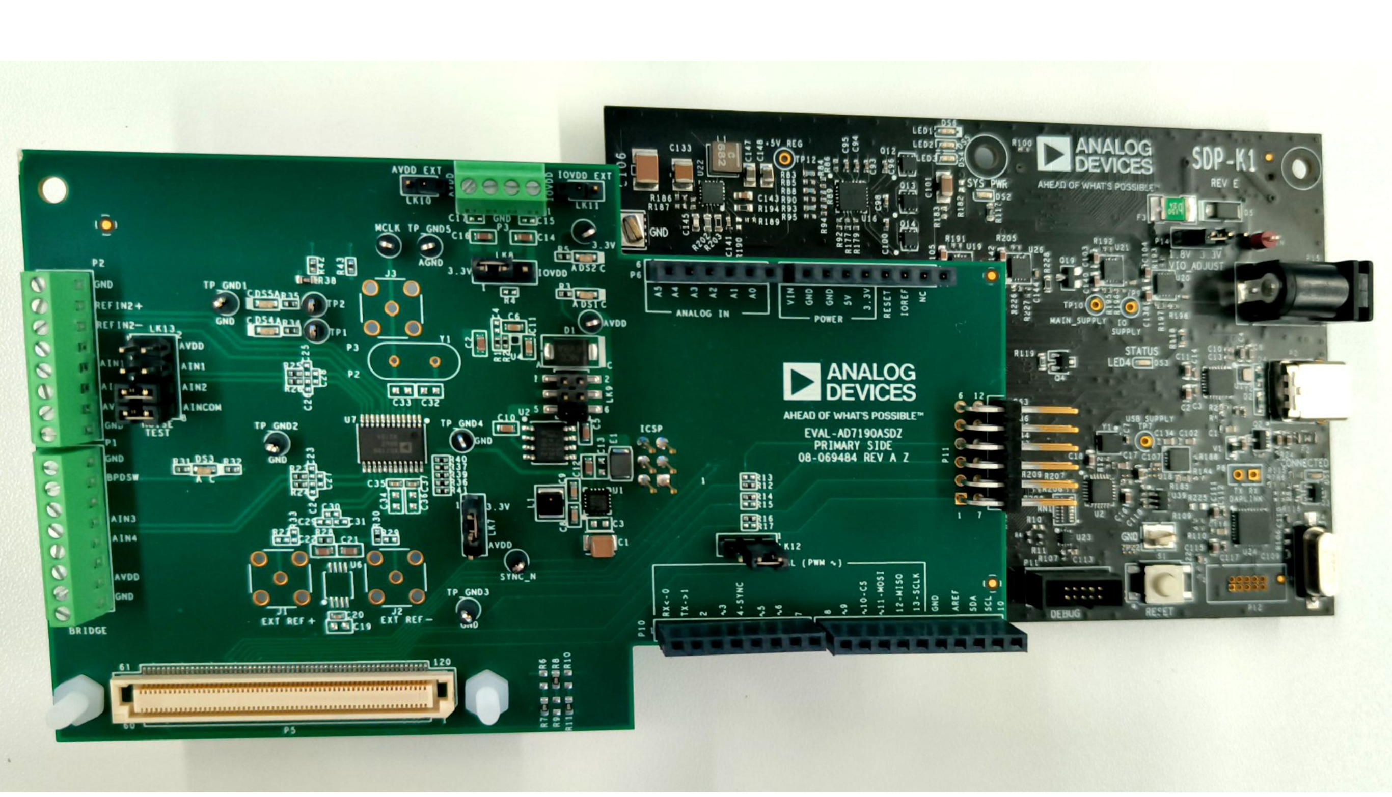
EVAL-AD719x-ASDZ + EVAL-SDP-CK1Z
Using the 120-pin connector: screw the two boards together using the plastic screw-washer set included in the evaluation board kit to ensure that the boards are connected firmly together.
Using the Arduino connectors:
EVAL-AD719x-ASDZ + EVAL-SDP-CB1Z
Using the 120-pin connector: screw the two boards together using the plastic screw-washer set included in the evaluation board kit to ensure that the boards are connected firmly together.
EVAL-AD719x-ASDZ + Cora Z7
Using the Pmod JA connector (default HDL configuration).
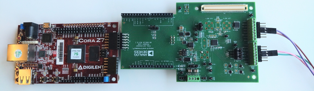
Using the Arduino shield connector (HDL built with
ARDZ_Pmod_N=1).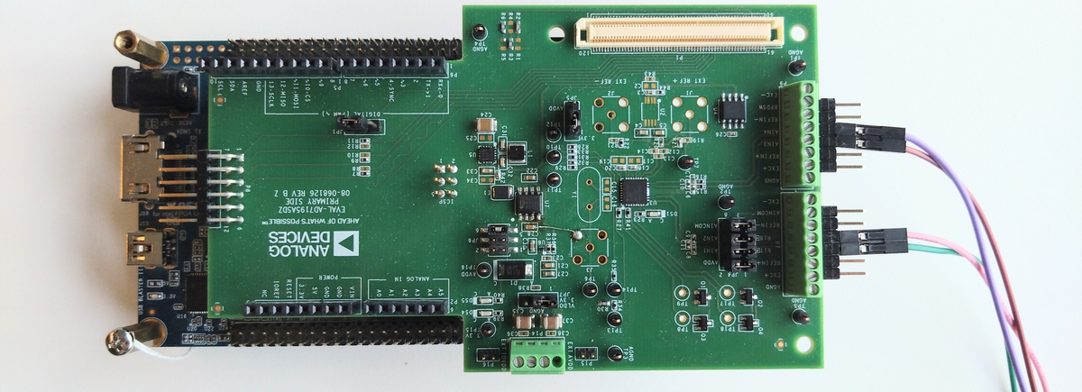
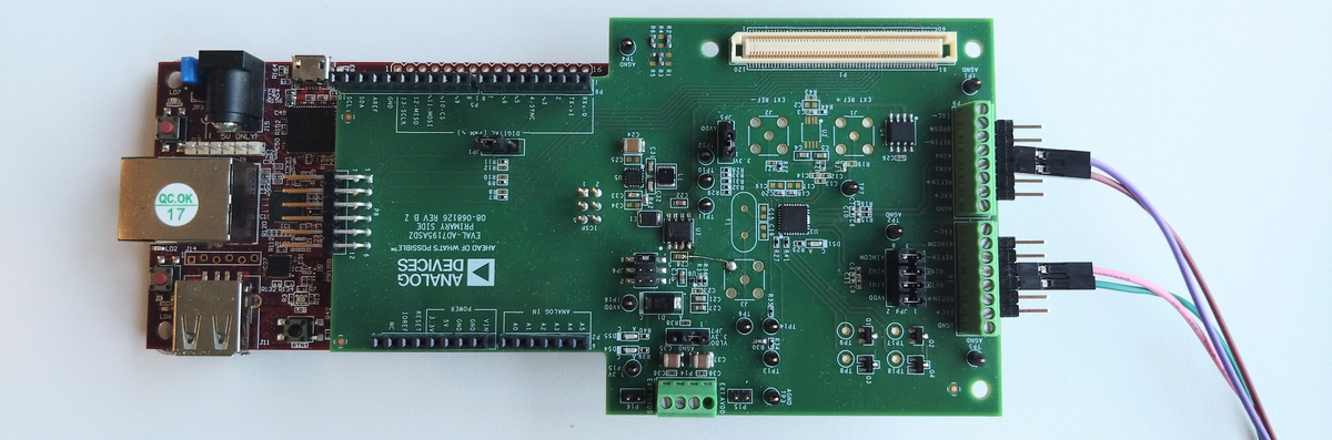
EVAL-AD719x-ASDZ + DE10-Nano
Using the Arduino shield connector.
Getting started
Once the hardware is set up, follow the Software guide for ACE plugin installation, operation, and demo modes.