PulSAR ADC PMOD Boards
Overview
The PulSAR ADC PMOD boards are evaluation modules featuring low-power ADCs offering 14 to 18-bit resolution with throughputs ranging from 100 kSPS to 1.33 MSPS. These boards are designed to demonstrate the ADC’s performance and to provide an easy to understand digital interface for a variety of system applications. A full description of each product is available in their respective data sheets and should be consulted when utilizing the evaluation boards.
Evaluation Board |
Part |
Resolution |
Throughput (kSPS) |
Input Type |
Driver |
|---|---|---|---|---|---|
14-bit |
250 |
Unipolar, Single-Ended |
|||
14-bit |
500 |
Unipolar, Single-Ended |
|||
16-bit |
100 |
Unipolar, Single-Ended |
|||
16-bit |
250 |
Unipolar, Single-Ended |
|||
16-bit |
250 |
Unipolar, Differential |
|||
16-bit |
500 |
Unipolar, Single-Ended |
|||
16-bit |
500 |
Unipolar, Differential |
|||
16-bit |
500 |
Unipolar, Differential |
|||
16-bit |
500 |
Unipolar, Single-Ended |
|||
16-bit |
1000 |
Unipolar, Single-Ended |
|||
16-bit |
1333 |
Unipolar, Single-Ended |
|||
18-bit |
400 |
Unipolar, Differential |
|||
18-bit |
250 |
Unipolar, Differential |
|||
18-bit |
1000 |
Unipolar, Differential |
|||
18-bit |
1333 |
Unipolar, Differential |
Note
The throughput of the PulSAR ADC will be limited to the SPI bus speed of the host platform (maximum 30 MHz on the SDP platform).
Hardware Setup
Power Supply Requirements
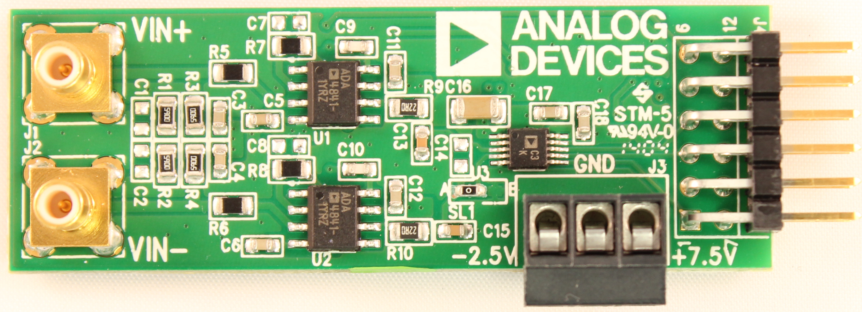
The PulSAR ADC PMOD boards are approximately 1 inch wide by 3 inches long. While standard PMOD connectors typically supply up to 100 mA at 3.3V, the successive approximation ADC architecture requires low-noise external power supplies to achieve data sheet performance. The precision amplifiers require supplies above and below the ADC input range to provide zero and full-scale inputs.
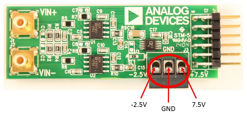
External power supply connections (via terminal block):
-2.5V — Amplifier negative rail
GND — Ground reference
+7.5V — Amplifier positive rail and on-board regulators
Warning
Connect external power supplies with the supplies turned OFF. Turn on the power supplies only after all connections are made.
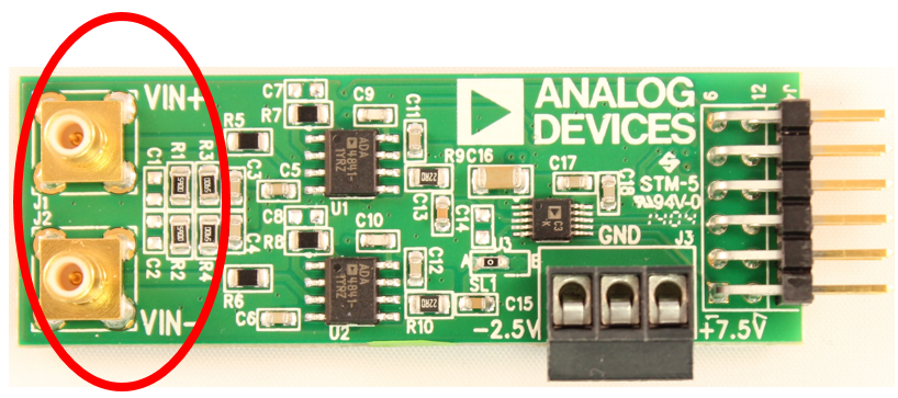
Input Connectors
Two SMB connectors per board accommodate positive (Vin+) and negative (Vin-) input signals. Using SMB connectors minimizes input noise at the input stage and fully utilizes the converter’s resolution and speed capabilities.
Each converter supports single-ended, differential, or pseudo-differential inputs depending on the specific model. Consult the device data sheet for the correct input configuration.
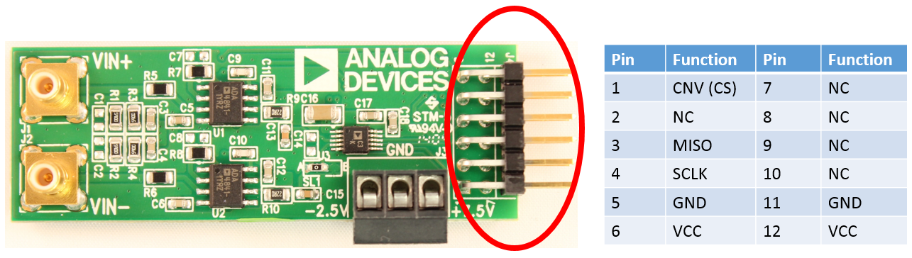
Digital Interface (PMOD)
The digital interface uses the extended SPI protocol per the Digilent specification. The boards operate in 3-wire mode without busy indication, using three signals:
CNV — Conversion trigger (similar to chip select)
SCLK — Serial clock
MISO — Serial data output (ADC data)
Since PulSAR ADCs contain no internal registers, no MOSI (input) line is required. Data streams directly via the CNVST pin upon completion of each conversion.
SDP Evaluation Setup
Equipment Required
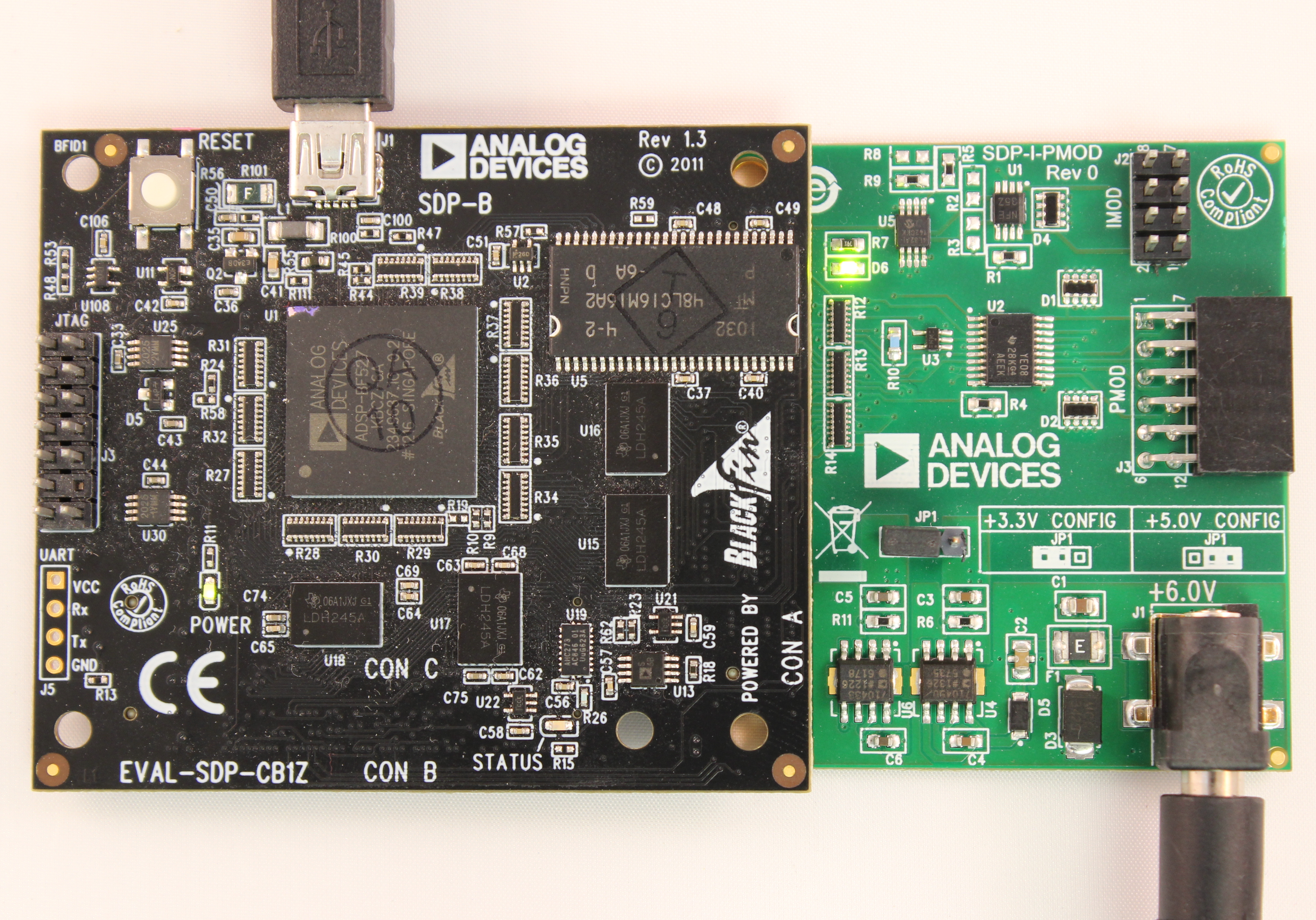
PulSAR ADC PMOD board (EVAL-AD7xxx-PMDZ)
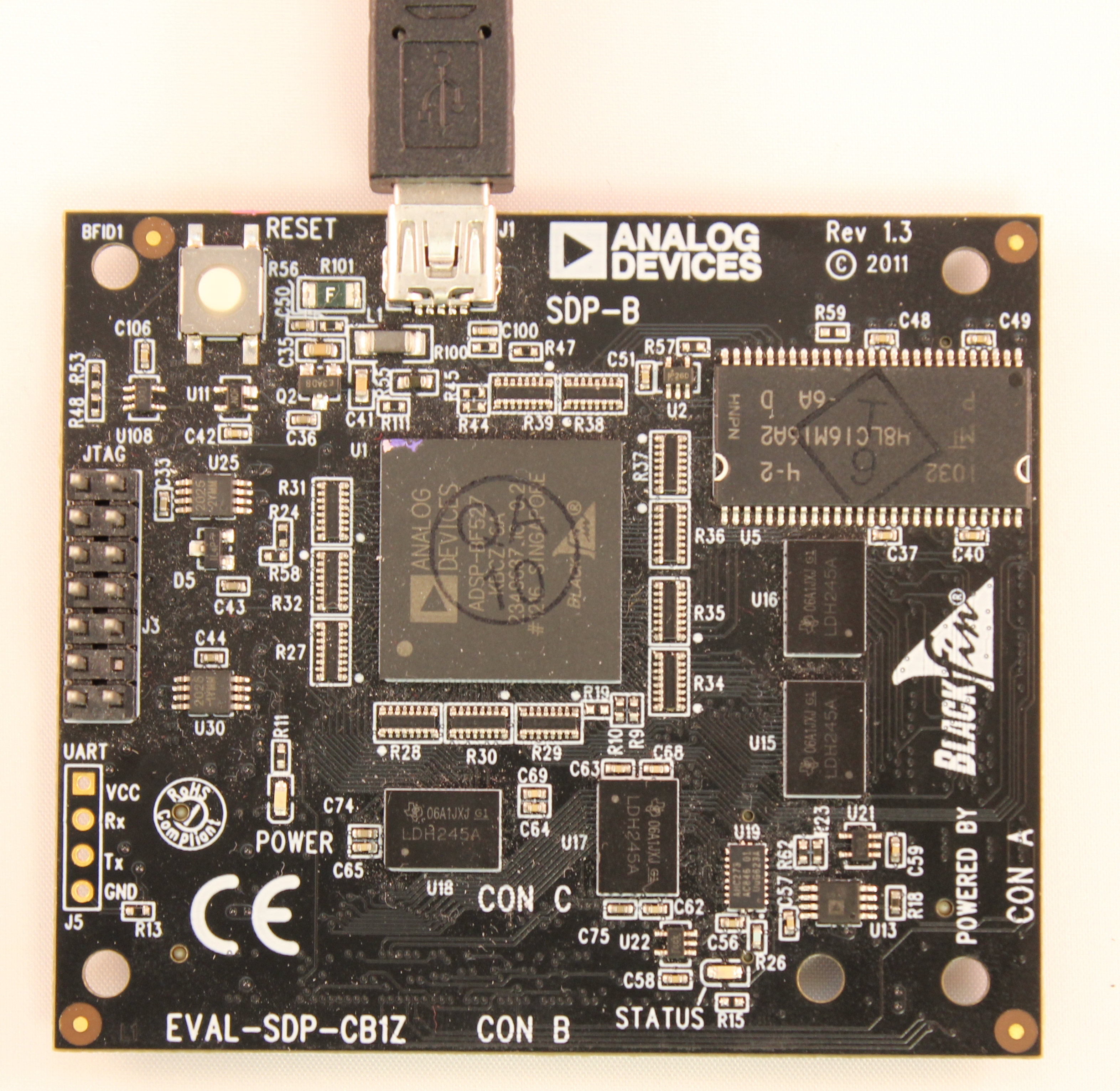
EVAL-SDP-CB1Z evaluation board
SDP-PMD-IB1Z PMOD interposer board
EVAL-CFTL-6V-PWRZ power supply
PC with Windows (.NET 3.5 or higher)
Mini USB cable
Low distortion signal source and appropriate cabling
Bench-top power supply (-2.5V, GND, +7.5V)
Hardware Setup
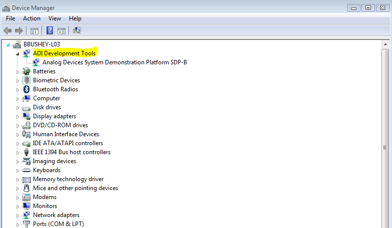
Connect the Mini USB cable from the PC to J1 of the EVAL-SDP-CB1Z. Verify that ADI Development Tools appears in Device Manager.
Remove the shunt at JP1 of the SDP-PMD-IB1Z interposer.
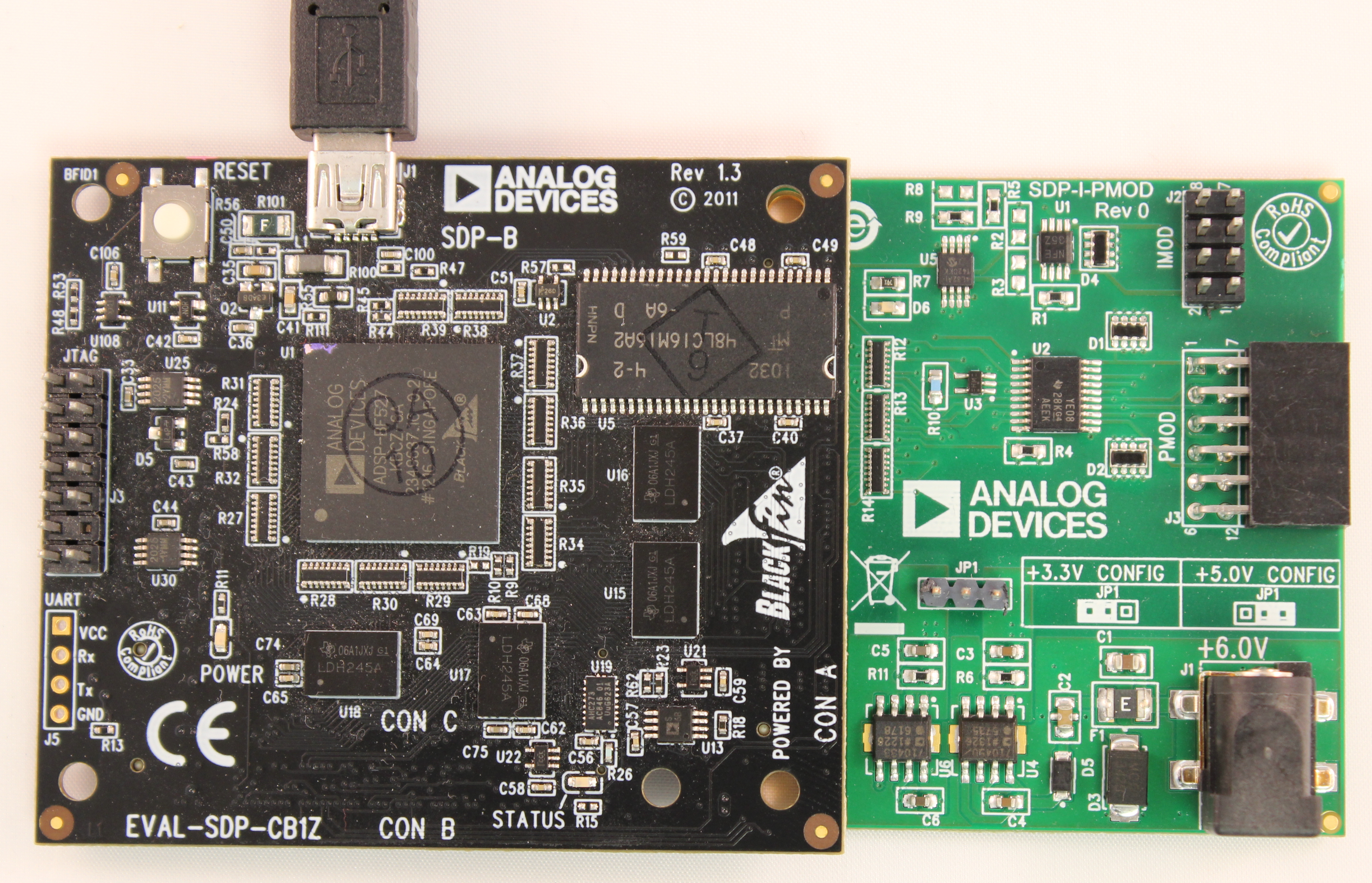
Connect the EVAL-SDP-CB1Z CON A to the SDP-PMD-IB1Z J4.
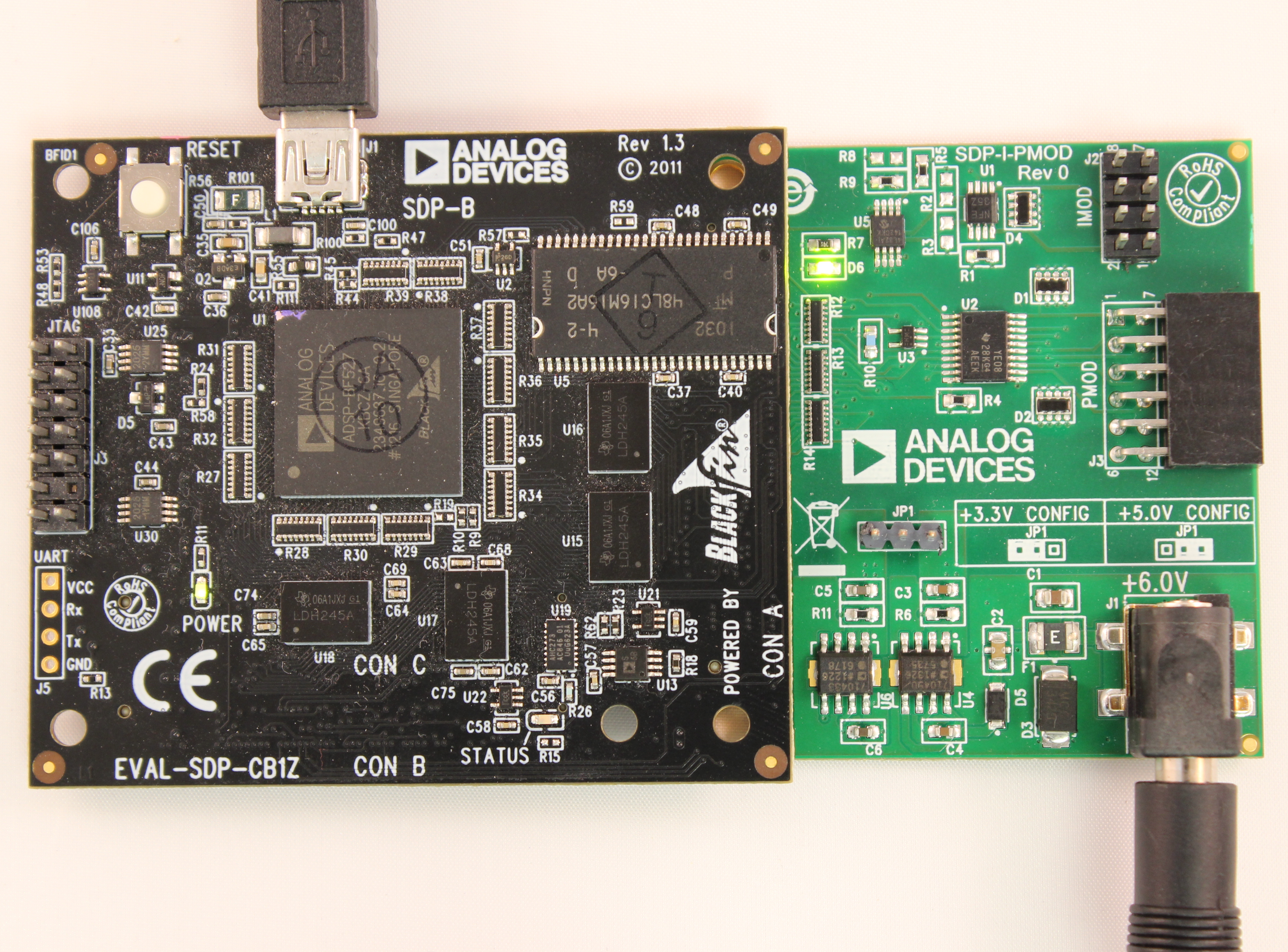
Connect the EVAL-CFTL-6V-PWRZ to the SDP-PMD-IB1Z J1 barrel jack. Wait 10 seconds for power stabilization.
Insert the PulSAR ADC PMOD board into the SDP-PMD-IB1Z J3.
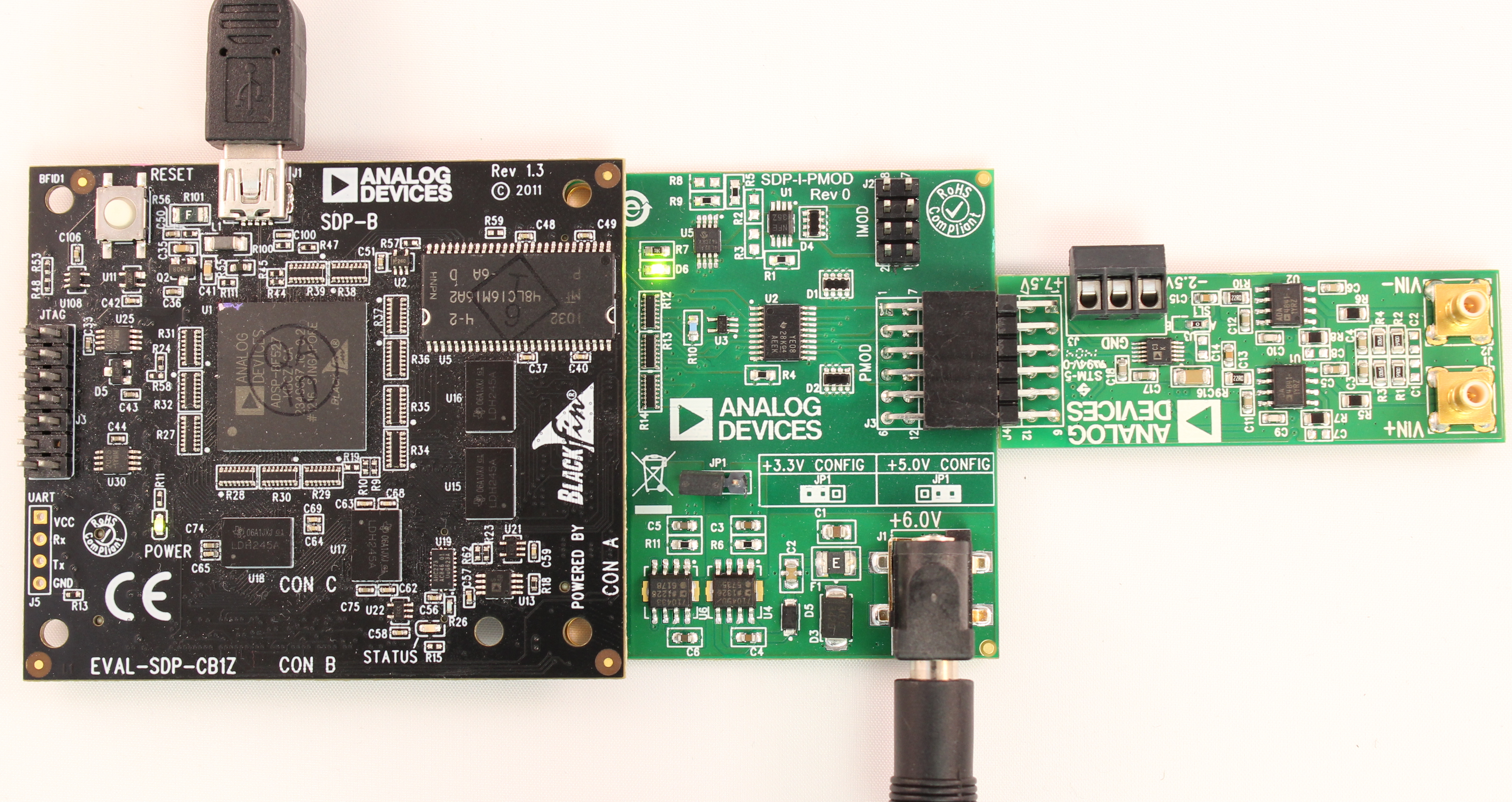
With external power supplies OFF, connect -2.5V, GND, and +7.5V to the terminal block on the EVAL-AD7xxx-PMDZ board.
Turn ON the external power supplies.
Place the shunt across JP1 of the SDP-PMD-IB1Z to enable 3.3V to the PMOD connector (see silkscreen for orientation).
Verify that ADI Development Tools is still visible in Device Manager.
Connect SMB cables from the signal source to the Vin+ and Vin- connectors of the EVAL-AD7xxx-PMDZ board.
Evaluation Software
A LabVIEW-based evaluation application provides the following controls:
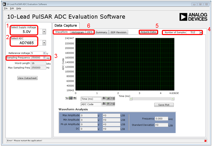
Control Panel:
Select Supply Voltage — Choose 5.0V or 2.5V corresponding to the ADC VDD supply.
Select ADC — Select the part number. Choices are filtered by voltage selection; parts incompatible with the selected voltage are grayed out.
Sampling Frequency — Enter the desired frequency in Hz (for example, 250000 for 250 kHz). Do not exceed the converter’s maximum sample rate.
Number of Samples — Select the number of samples for waveform, histogram, and FFT calculations.
Acquire Data — Click to gather data and calculate results.
Data Display Tabs:
Waveform — Time-domain representation of captured data
Histogram — Bin-based data distribution for noise analysis
FFT — Frequency-domain analysis with SINAD, THD, and SNR calculations
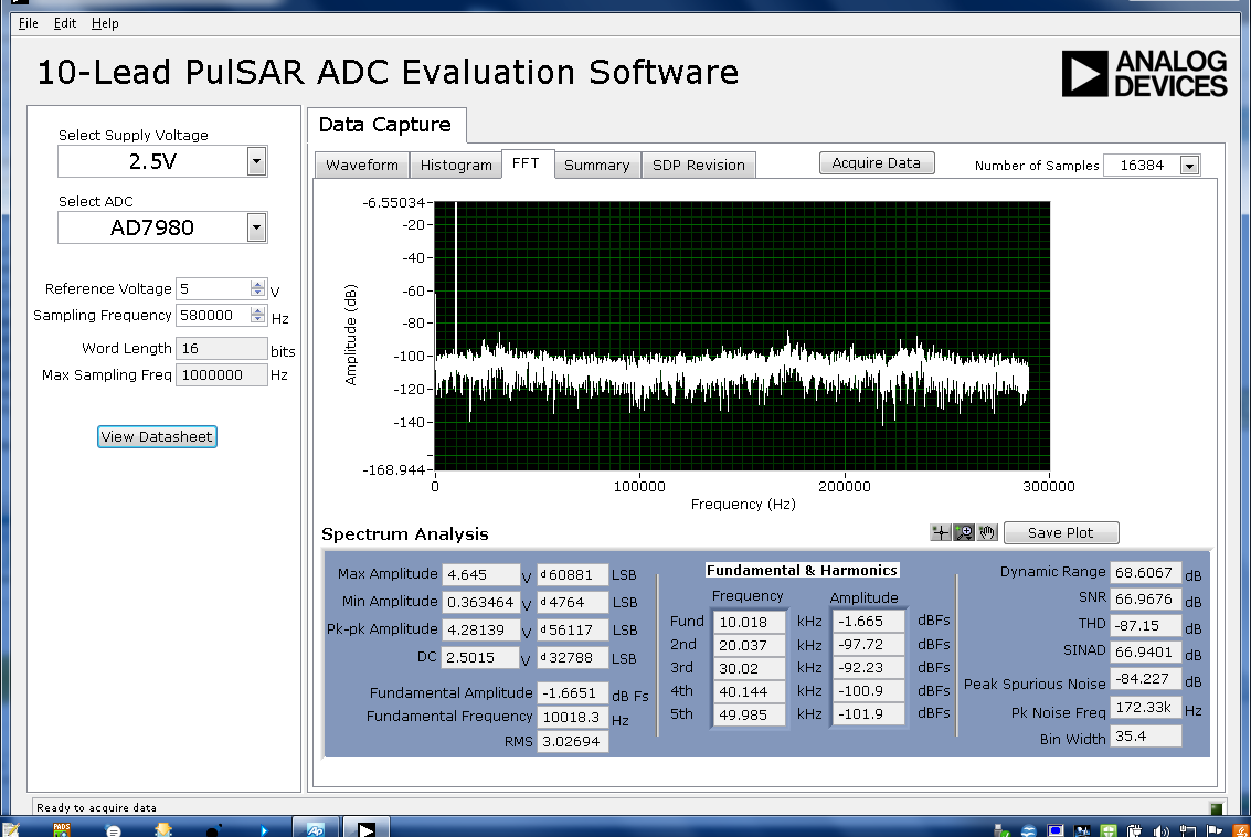
Figure 12 FFT analysis example using AD7980 with 10 kHz input sine wave
FPGA Carrier Setup
The PulSAR ADC PMOD boards are also supported on FPGA carrier boards for use with HDL reference designs and Linux/no-OS drivers. For FPGA-based evaluation, see the PulSAR ADC quick start guides.
Design & Integration Files
Complete design support packages including schematics, PCB layout, bill of materials, and Allegro project files are available for download from the respective evaluation board product pages on analog.com:
Revision History
Changes from Rev 0 to Rev A:
Migrated from PADS to Allegro CAD tools (reference designators changed)
Replaced capacitors C9 and C10 with resistors R5 and R7
Added R16 and R17 for extended ADC operating modes (daisy-chain capability)
Removed U5 (ADG1401) multiplexer; connected 5V reference directly to ADC
Removed U8 (ADP7104-3.3) regulator; connected VIO pin to VCC
Separated analog (AGND) and digital (DGND) ground planes