Hardware
This page covers the basics of Jupiter hardware and what a user should know to use the hardware. An in-depth hardware guide can be found here.
I/O
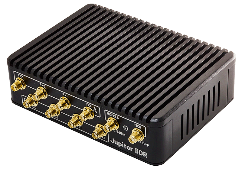
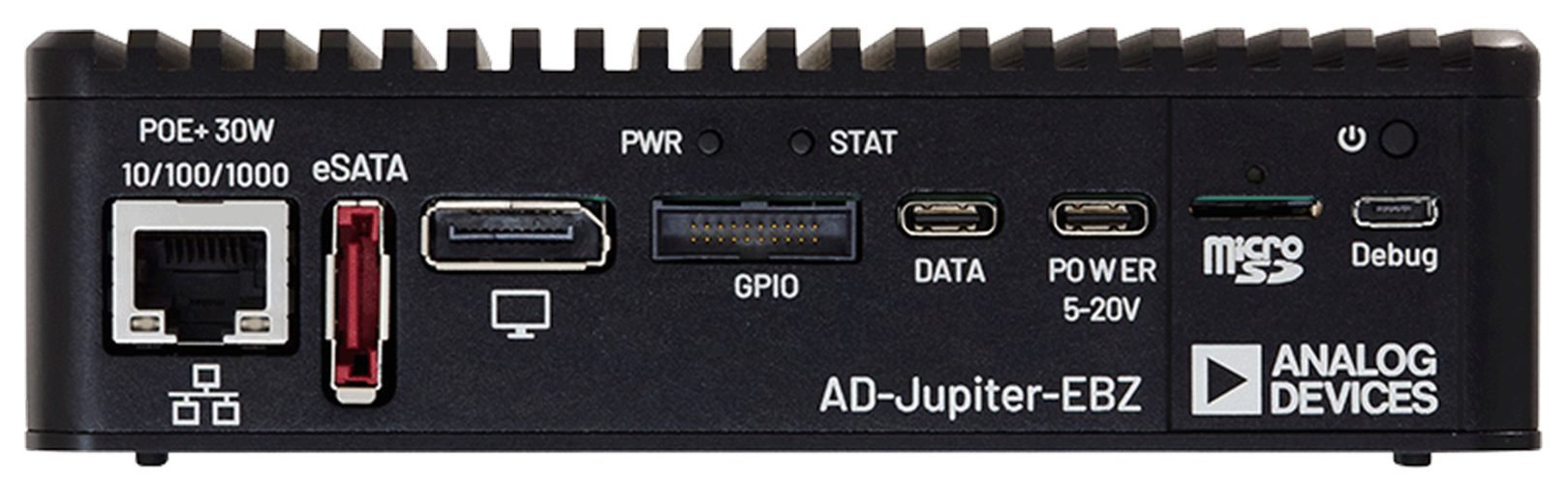
In terms of I/O, Jupiter exposes 10 SMA connectors on the front panel for Tx, Rx, MCS, and external device clock (DEV CLK) signals. Host interfaces include Gigabit Ethernet, USB 3.1, DisplayPort, and a GPIO interface. The board supports two power input options, USB-C and Power over Ethernet (PoE).
Configurations
There are two configurations for Jupiter: Host Computer Mode and Standalone Mode.
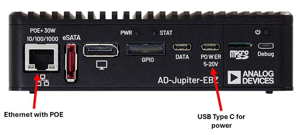
Host Computer Mode
Micro-USB cable
USB Type-C cable (or Ethernet cable)
USB Type-C Power Supply
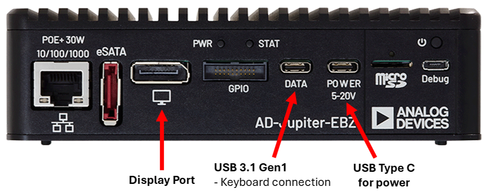
Standalone Mode
DisplayPort compatible Monitor
USB Type-C multiport hub, mouse and keyboard
USB Type-C Power Supply
RF Front-End
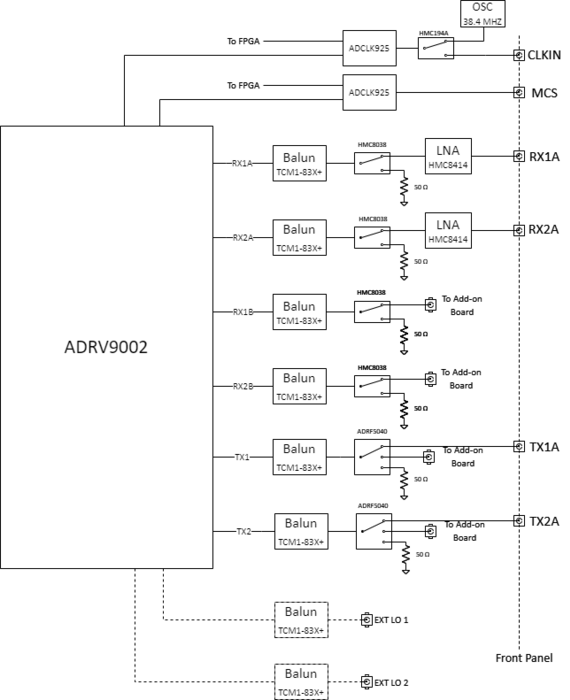
Receive Channels (Main Board – RX A)
RX1A and RX2A exposed on the front panel
Connected to ADRV9002 Rx A channels
Wideband frequency range: 100 MHz to 6 GHz
Bypassable HMC8414 LNA
HMC8038 non‑reflective SPDT switch
Supports internal calibration with 50 Ω termination
TCM1‑83X+ Mini‑Circuits balun
Calibration switch controlled by driver (not user‑accessible)
Receive Channels (Main Board – RX B)
RX1B and RX2B connected to ADRV9002 Rx B channels
Routed to the RF Add‑On board via u.FL cables
Includes the same SPDT switch and balun as RX A paths
Transmit Channels
TX1A and TX2A exposed on the front panel
Connected to ADRV9002 Tx channels
TCM1‑83X+ balun on each transmit path
ADRF5040 three‑way non‑reflective RF switch
Supports TX output disconnection during internal calibration
Supports routing TX path to RF Add‑On board
User‑selectable attributes for:
TX1A vs TX1B
TX2A vs TX2B
Block Diagram
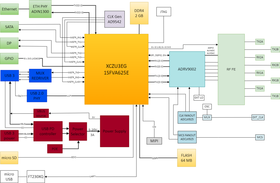
Processing
|
Memory & Storage
|
RF Subsystem
|
Clocking & Sync
|
Power
|
Interfaces
|
Note
For questions or help with the Jupiter SDR, please visit:
EngineerZone