ZCU102 Configuration
This guide covers the hardware configuration settings required for the Xilinx ZCU102 Evaluation Board to properly interface with the X-Band Phased Array Development Platform.
Overview
The ZCU102 requires specific jumper and switch settings to:
Boot from SD card with Kuiper Linux
Enable USB host mode for peripherals (keyboard, mouse)
Configure UART communication for debug console
Set up network connectivity for remote access
Important
Configure these settings before first power-on to ensure proper system operation.
Boot Mode Configuration
The ZCU102 supports multiple boot modes (JTAG, SD card, QSPI, etc.). For X-Band platform operation, SD card boot mode is required.
SW6 Boot Mode Switch Settings
Locate SW6 on the ZCU102 board:
Position: Halfway between the SD card slot and the vertical SMA connectors
Type: 4-position DIP switch
Purpose: Selects primary boot source
Configure SW6 for SD Card Boot:
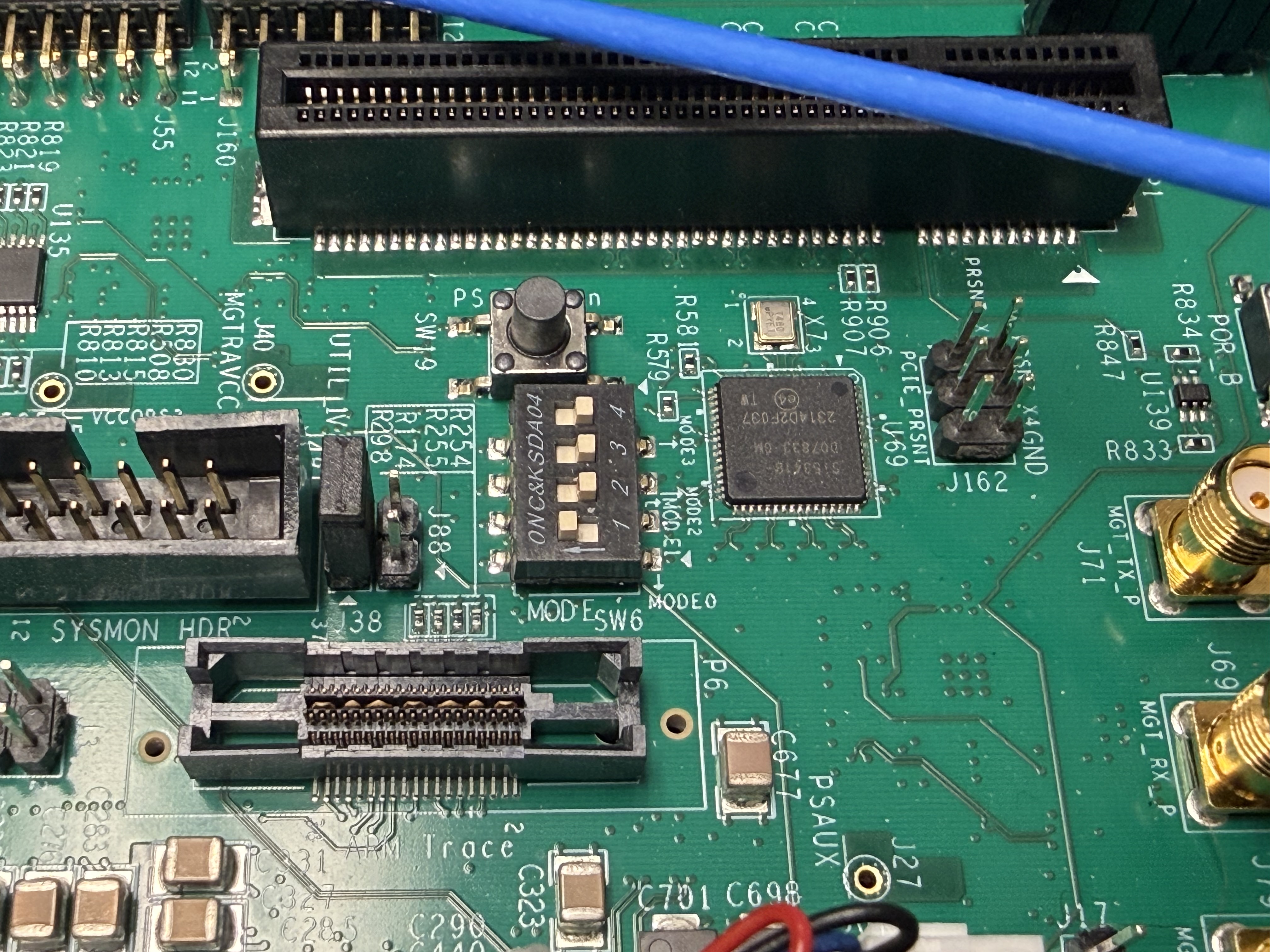
Switch |
Position |
Description |
|---|---|---|
SW6.1 |
ON |
Boot mode bit 0 |
SW6.2 |
OFF |
Boot mode bit 1 |
SW6.3 |
OFF |
Boot mode bit 2 |
SW6.4 |
OFF |
Boot mode bit 3 |
Warning
Incorrect boot mode settings will prevent the ZCU102 from booting from the SD card. Always double-check SW6 configuration before applying power.
If boot fails, verify SW6 settings and SD card preparation.
USB Configuration
The ZCU102 provides USB ports that can operate in different modes. For X-Band platform, configure for USB host mode to support peripherals.
USB Host Mode Jumper Settings
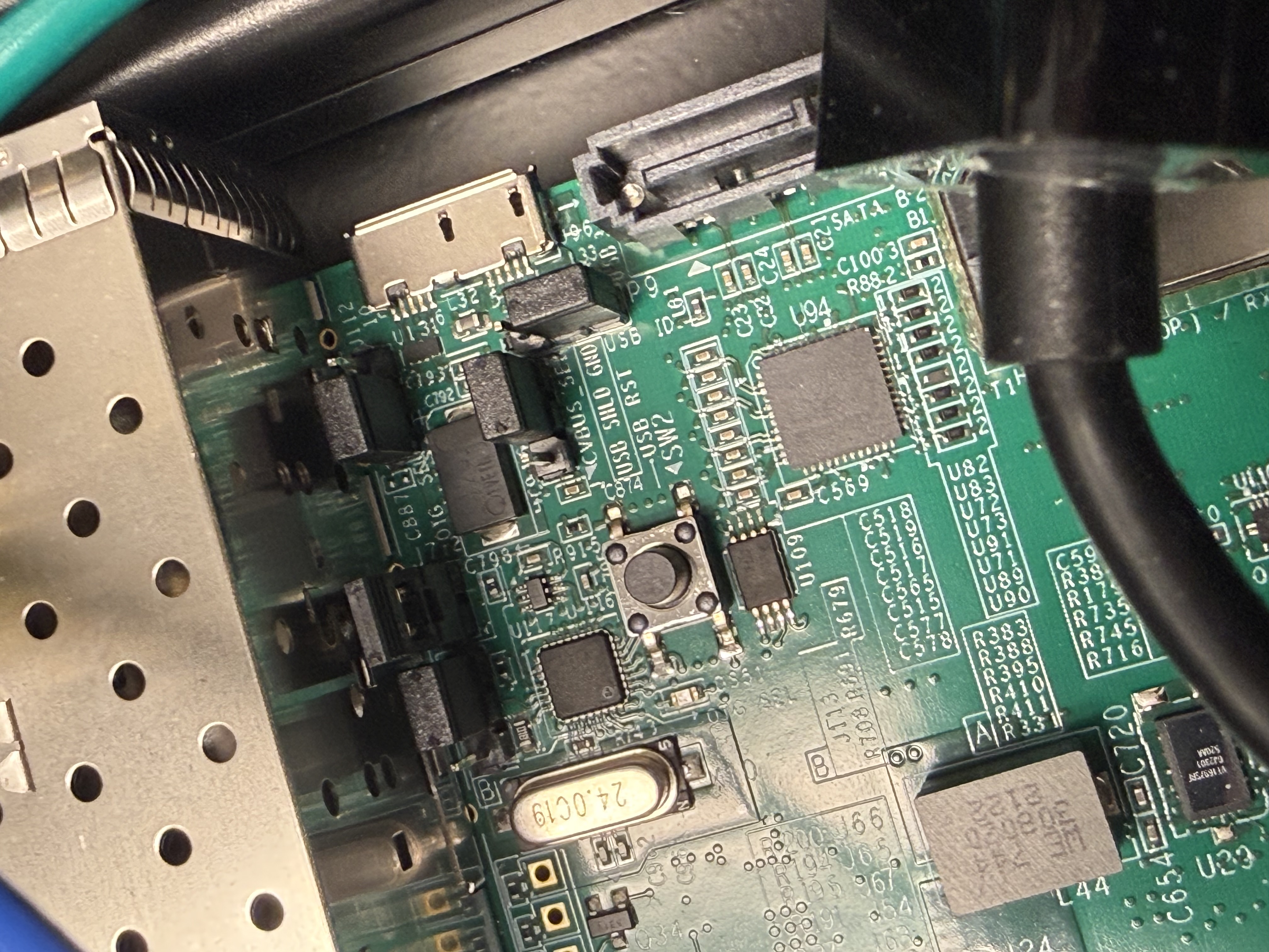
Configure the following jumpers for USB host operation:
J7 - USB Power Enable
Shunt J7: Enables USB power to downstream devices
Location: Near USB Type-A ports
J109 - USB2.0 PHY Configuration
Position: Pins 2-3 shunted
Purpose: Configures USB2.0 PHY for host mode
J110 - USB3.0 PHY Configuration
Position: Pins 2-3 shunted
Purpose: Configures USB3.0 PHY for host mode
J112 - USB Mode Selection
Position: Pins 1-2 shunted
Purpose: Selects host mode operation
J113 - USB VBUS Configuration
Position: Pins 1-2 shunted
Purpose: Provides VBUS power for host mode
Tip
Quick Reference: For USB host mode, set:
J7: Shunted
J109: 2-3
J110: 2-3
J112: 1-2
J113: 1-2
USB Host Mode Verification
After configuring USB settings:
Connect USB keyboard or mouse
Power on ZCU102
Check device enumeration in Linux:
root@analog:~# lsusbYou should see your connected USB devices listed
Check kernel messages:
root@analog:~# dmesg | grep -i usb
Look for successful USB device detection
UART Configuration
The ZCU102 provides a USB-to-UART bridge for console access via USB.
Hardware Setup
USB-UART Connection:
Connector: J83 (USB Micro-B)
Cable: USB Micro-B to USB-A
Chip: Silicon Labs CP2108 quad UART bridge
Physical Connection:
Connect USB Micro-B cable to J83 on ZCU102
Connect USB-A end to your host computer
Wait for driver installation (if first time)
Driver Installation
Windows
If the bridge is not automatically recognized:
Download driver from Silicon Labs VCP Drivers
Install the CP210x USB to UART Bridge VCP Driver
Reboot if required
Verify COM port appears in Device Manager
Terminal Settings
Configure your terminal emulator with:
Parameter |
Setting |
|---|---|
Baud Rate |
115200 |
Data Bits |
8 |
Parity |
None |
Stop Bits |
1 |
Flow Control |
None |
Common Terminal Emulators:
Windows: PuTTY, TeraTerm, RealTerm
Linux: minicom, screen, picocom
macOS: screen, minicom, CoolTerm
Example PuTTY Configuration (Windows):
Select “Serial” connection type
Enter COM port number (e.g., COM3)
Set speed to 115200
Open connection
UART Port Mapping
The CP2108 provides 4 UART channels:
Channel |
Function |
Usage |
|---|---|---|
UART0 |
PS UART0 |
Primary console - use this |
UART1 |
PS UART1 |
Secondary console |
UART2 |
PL UART |
FPGA fabric UART |
UART3 |
PMU |
Platform Management Unit |
Important
Connect to the first UART port (UART0/Channel 0) for the main Linux console. The exact COM port or /dev/ttyUSB* number depends on how many other USB serial devices are connected.
References and Resources
See also
SD Card Configuration - Prepare boot media with Kuiper Linux
EEPROM Programming - Program FMC EEPROM for VADJ power
Assembly Guide - Complete hardware assembly instructions